24th Aug 2010, 23:43
permalink Post: 105
ChristiaanJ
Loved your AICU stuff. Here's an extract from 'The Concorde Air Intake Control System':
The Control Highway
This highway is a uni-directional databus that carries binary data transmitted by the AISU to it's pair of AICU's. The Control Highway effectively comprises of a single wire, that has transmitted along it multiplexed digital data, clock and address. (In reality this is a twisted wire pair). The AICS Control Highway data word comprises of 64 bits, transmitted at a PRF of (at least by modern standards) an extremely pedestrian 35 Kbits/second.
Sounded mouthwatering in the 1970's though, 35 Kbits/sec' is almost NINE KB/sec'!!!!.
Dude
Last edited by M2dude; 25th Aug 2010 at 00:11 .
25th Aug 2010, 22:17
permalink Post: 122
Quote:
|
Originally Posted by
DozyWannabe

Any magnetic core memory in any of those systems?
|
The prototypes used a SAGEM/Ferranti system, replaced by a Litton system on the preprods, then Delco on the production aircraft.
There may have been magnetic core in the prototype INS.
As to the AICS (air intakes) and AFCS (automatic flight control), the answer is a definite NO. The AICUs used PROMs (fuse type, not EPROM) and the AFCS was entirely analog.
Some of the systems were even more 'antique'...
The ADC (air data computer) for instance was still largely electro-mechanical.
And those nifty NAV and COMM frequency selectors, that always stand out on cockpit pictures... no electronics at all, just a set of wafer switches, and about thirty wires linking them to the transmitters/receivers.
CJ
18th Nov 2010, 12:47
permalink Post: 725
Landroger
It always was a bit of a paradox; in terms of fuel price and environmental concerns, Concorde was about 5 years too late. But in ELECTRONICS terms she was 10 years too early. Bearing in mind that the first Intel 4004 was not even commercially available until 1971. When the decision was taken in late 1970 to 're-design' the analog air intake control system into a digital one, there was nothing to fall back on; a BAC custom guided missile processor (used I believe on both the Rapier and Sea Dart SAMs) had to be adapted. This processor was, as I've yawned on about before, comprised of multiple double sided PCBs completely stacked with TTL ICs. In spite of being a total antique and a dinasore (just like me
 ) this thing was really cutting edge technology at the time, even using a 64 bit data word. The AICS as again I've yawned on about before, was the WORLD's first commercial airborne digital control sysstem, but the Concorde analog stuff in fact worked pretty well indeed.

Galaxy Flyer
As always GF you make your point really well. As far as Concorde went, the very few American (Branniff) pilots who flew her thought she was totally amazing, and the American BA engineers at JFK and IAD absolutely adored the aeroplane.
And back to your 'charriot', the C5 has been a staggeringly successful aeroplane in terms of US service. and is still thriving (big modernisation programme underway). Not bad for an aircraft that entered USAF service in 1969!!!
Regards
Dude
Quote:
It is
still
difficult to grasp the fact that, with the one exception Christiaan has told us about, all of the control electronics in Concorde were
analogue.
Some of the little tweaks Dude has just alluded to in his reply about the nozzles and the relationship of compressor speeds, for example. Most of them would be relatively easy - relative is a huge word of course

|
) this thing was really cutting edge technology at the time, even using a 64 bit data word. The AICS as again I've yawned on about before, was the WORLD's first commercial airborne digital control sysstem, but the Concorde analog stuff in fact worked pretty well indeed.
Galaxy Flyer
As always GF you make your point really well. As far as Concorde went, the very few American (Branniff) pilots who flew her thought she was totally amazing, and the American BA engineers at JFK and IAD absolutely adored the aeroplane.
And back to your 'charriot', the C5 has been a staggeringly successful aeroplane in terms of US service. and is still thriving (big modernisation programme underway). Not bad for an aircraft that entered USAF service in 1969!!!
Regards
Dude
22nd Dec 2010, 20:40
permalink Post: 951
Before adding my own little bit to Clive's earlier reply about the autotrim, I will try to explain, for those not fully familiar with the subtleties of automatic flight control, the difference between "closed loop" and "open loop".
Closed loop
As an example, let's look (very simplified) at how the autopilot maintains a selected altitude.
On the one hand we have the desired altitude as selected on the autopilot controller (here 40,000 ft).
On the other hand we have the true altitude , as measured by the altimeter (let's say 39,000 ft).
We subtract the two to obtain the altitude error (in this case 39,000-40,000=-1,000 ft).
We 'multiply' the altitude error by a factor, the gain (for the discussion, let's assume this gain is 1 degree elevon per 1000 ft altitude error), and send the resulting elevon position command to the elevon.
So, the elevon moves 1\xb0 nose-up, the aircraft starts to climb, the altitude increases and the altitude error decreases until it becomes zero, by which time the elevon position has also returned to zero.
What we have now is a "closed loop" : any deviation from the selected altitude results in an elevon command in the opposite direction, until the deviation is again reduced to zero.
Another commonly used term is "feedback" : any error is fed back in the opposite sense until it's reduced to zero.
The significant figure here is the 'gain'.
If the gain is too small, the autopilot response to a disturbance (say turbulence) will be sluggish ; the aircraft takes too long to return to the desired altitude.
If the gain is too high, a small disturbance will cause the aircraft to start climbing too rapidly, and to overshoot the desired altitude, then descend to correct the new error, etc.
In other terms, the control loop is no longer stable, but starts to oscillate.
Both theory and practice show that the exact value of the gain is not all that critical, a few percent more or less do not markedly change the response of the loop.
Note: a "closed control loop" as described above can be implemented in just about any way you like.
It can be done purely mechanically, with a few clever clockwork mechanisms 'computing' the altitude error and controlling the elevator pneumatically or hydraulically. It's how the earliest autopilots worked.
After that came electromechanical systems, analogue computers and then digital computers... but the principle has remained unchanged.
Open loop
As already described in earlier posts, the situation with the automatic trim is the opposite.
We now need to compute a neutral elevon position from several data, such as Mach number or airspeed, but without any feedback as to whether our computations are correct.
We're now working in "open loop".
To complicate matters... that neutral elevon position is not a simple linear function of Mach and airspeed, but far more complex (see the earlier posted graphs).
And because of the large response of the aircraft to small changes in trim, in particular in the transonic regions, those computations have to be far more accurate : a one degree error is simply not acceptable.
In the end.....
The AICS (air intake control system) also uses several "open loop" functions.
The early development aircraft still had an analogue system, which proved all too soon to be inadequate, so, at a very late stage, it was replaced by a digital system (one of the rare digital systems on Concorde).
The "open loop" functions of the autotrim system initially had the typical "a few" percent" accuracy of the other flight control systems, which, for the autotrim, also proved inadequate.
We managed to "save the furniture" (as they say in French) by using 0.1% components in all the critical computing paths, so the autotrim computers remained analogue until the end.
But, a slide rule is not accurate to 0.1%... So that's when I had to buy my very first pocket calculator.
\xa342 at 1972 prices... just as well the firm paid.
CJ
23rd Dec 2010, 08:54
permalink Post: 961
CliveL
Tee hee, can't get away with anything here anymore Clive
Yes, of course (as ever
 ) you are correct; it was technically a hybrid system: The servo loops, in terms of ramp and spill door demand signals and resolver position feedback signals etc. DID use conventional analogue drive and servo amplifiers within the AICU, it was the massive arithmetic computation UP-STREAM of these that was digital. I always used to like to refer to the AICS as 'an analog front end with a digital brain'. But that's just me
 .
.
But as you say Clive, none of the control law sophistication (including the synthesising the intake face total pressure and local Mach numbers from mainline aircraft raw air data) would have been possible using analog computation.
Best regards
Dude
Quote:
| I've noticed that several postings refer to the production AICU as a 'digital' control system. Strictly speaking it wasn't; it was a hybrid digital/analogue system where the inner dynamic control loops (the closed loop part) were analogue systems operating to maintain limits defined by the digital arithmetic processors. This allowed us to have quite sophisticated control 'laws' which would have been next to impossible with a pure analogue system. |
Yes, of course (as ever
) you are correct; it was technically a hybrid system: The servo loops, in terms of ramp and spill door demand signals and resolver position feedback signals etc. DID use conventional analogue drive and servo amplifiers within the AICU, it was the massive arithmetic computation UP-STREAM of these that was digital. I always used to like to refer to the AICS as 'an analog front end with a digital brain'. But that's just me
.
But as you say Clive, none of the control law sophistication (including the synthesising the intake face total pressure and local Mach numbers from mainline aircraft raw air data) would have been possible using analog computation.
Best regards
Dude
7th Jan 2011, 13:13
permalink Post: 1079
The thar intakes
Clive & Christian
Gentlemen, I think you will find that 102 did indeed have a totally 'unique' analog intake control system. Not only were the RDCUs (not AICUs in this case chaps) totally different, there were major architectural changes over the prototype system too. Also, although the basic intake structure was the same as 101 and all subsequent aircraft, there was still the prototype approach to local pressure sensing adapted, ie. Intake face total pressure P∞ sensed directly via the infamous 'magic holes' rather than using digitally synthesised values based on mainline aircraft manometric probe, total (pitot)pressure. As 101's intakes only went 'live' in mid-march 1973, I assumed that maybe they (AS) wanted an operative intake system from the outset on 102 when it first flew in January of that year. What puzzled me was why they went for this seemingly enhanced (and expensive) analog system on 102 and not the original system. (As 102 used a production type intake, I guess that they would have to have at least made some changes to the control system ; there was no exotic double hinged 'Dump Door', but the far simpler and elegant 'Spill Door' with integral Aux' Inlet Vane that was known and loved by us all). Rumour had it that AS still wanted to pursue the 'magic holes' solution and were dead against the decision to go digital. (This particular decision was taken in October 1970, which makes the 102 AICS route seem all the more strange).
And ChristiaanJ; what you guys achieved with the MAX CLIMB/MAX CRUISE was nothing short of remarkable. Just about the most exotic (and complex) autopilot mode that I've ever seen, that solved so MANY problems.
(Still the only A/P mode I've ever seen where the Autothrottle is engaged in a speed mode at the same time as the AUTOPILOT
).
Best regards
Dude
Last edited by M2dude; 8th Jan 2011 at 09:58 . Reason: 'All I want for Christmas is the ability to spell'
18th Jan 2011, 20:53
permalink Post: 1127
That is amazing Clive, these guys were indeed legend as far as the AICS development went. (And they were doing all that simulation work using analog computers too
. Here is the one of the 'forward' pages from 'The Concorde Air Intake Control System' publication: (Issue 3 Feb' 2001). There just might be a name or two there that rings a bell.
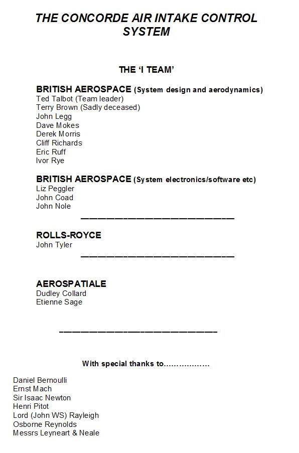
So much was achieved by such a very small team of people. An achievement that was absolutely pivotal to the successful development of Concorde.
With total respect
Dude
. Here is the one of the 'forward' pages from 'The Concorde Air Intake Control System' publication: (Issue 3 Feb' 2001). There just might be a name or two there that rings a bell.
So much was achieved by such a very small team of people. An achievement that was absolutely pivotal to the successful development of Concorde.
With total respect
Dude
19th Jan 2011, 12:34
permalink Post: 1129
The book
Poor old Etienne, yes he's a sage here rather than Fage,
 I never noticed that one before. I do remember that the late Terry Brown, who was part of your S & C department was a bit of a boat builder as well as being a brilliant aerodynamicist. But all these people were absolute masters of their craft, bad spelling and all, the result being something so very special and unique.
As far as the AICS book goes, there are quite a few copies (methinks a few hundred) that are dotted around; I'll see what I can find and PM you. There were so many of these 'lesser' Concorde works out there that are full of useful information about what made Concorde tick.
Best regards
Dude
.
I never noticed that one before. I do remember that the late Terry Brown, who was part of your S & C department was a bit of a boat builder as well as being a brilliant aerodynamicist. But all these people were absolute masters of their craft, bad spelling and all, the result being something so very special and unique.
As far as the AICS book goes, there are quite a few copies (methinks a few hundred) that are dotted around; I'll see what I can find and PM you. There were so many of these 'lesser' Concorde works out there that are full of useful information about what made Concorde tick.
Best regards
Dude
.
18th Oct 2013, 19:12
permalink Post: 1734
Dozy
Yeah, well when we put a digital computer to generate the AICS laws that was NEW man!
Again, no digital multifunction displays on offer in those days
Errrr no, I don't think so. Concorde's flight deck was done at Filton and we had no involvement in the Airbus designs in that area.
Exwok's remark is not quite right IIRC. Certainly the window size was dictated by pressurisation failure, but one couldn't maintain cabin pressure with two windows failed - the design case was to get to a breathable altitude before you killed too many passengers! Also, there is very little to see when you have a delta wing under you.
Ummm - most participants reckoned that the Concorde infrastructure showed the way not to do it, and besides the early Airbuses were developed in parallel with the later stages of Concorde development. You have a point where R&D is concerned though - several technologies developed for Concorde found their way onto the subsonic fleet, not the least being the probability approach to system certification.
Quote:
| Even when Concorde entered production, the most complex digital displays available to aviation were of the 7-segment LED type (as used in the Apollo Guidance Computer), and they were both wildly expensive and of limited use. |
Quote:
| Ergonomically speaking, both engineers and pilots of the era write of Concorde's flight deck being the best possible balance of form and function available at the time - sure it looks cluttered to the modern eye, |
Quote:
| It's worth bearing in mind that even those not particularly well-disposed to Airbus will grudgingly admit that the flight deck ergonomics on those types are extremely good - and a lot of the lessons learned were from cramming all that information into Concorde's limited space. |
Quote:
| I have to thank EXWOK for explaining the windows - but I'll add the more prosaic reason that you don't need a particularly large window to see the curvature of the Earth in all its splendour - which is for the most part all you'd be seeing during the flight! |
Quote:
| While Concorde herself never recouped the development money granted by the governments of the UK and France, the infrastructure and R&D her development put in place paved the way for the Airbus project |
8th Mar 2014, 18:15
permalink Post: 1806
Concorde AICU
Hi Christian,I was a development engineer at Filton working on the AICU at first but ending up in charge of avionics test.
So as far as your AICU is concerned - I have handled all the boards extensively.
I first worked on the "A" model - the first manufactured box, followed by "A bar" (logically, not "A").
These did not have the doghouse connector on the front, and in order to see what was going on in the program, we made a strobe unit hard wired to the digital boards, this was followed by the connector on the front and an AICU test box.
When first switched on the whole unit rattled at high speed as all the relays chattered.
I spent several days adding decoupling capacitors on all the boards.
The birds nest chassis wiring was chosen to prevent cross- talk.
This was at the start of 1972, but I can still remember a lot of it.
Someone mentioned a prom change at Casablanca, I carried out a prom change there just before the C of A flight.
I am a volunteer at the Bristol Aero Collection, and we have just received a drawing cupboard with the AICS drawings.
We are at the moment documenting archives. One of the volunteers is Ted Talbot who I used to work with, and has been mentioned in posts.
Feel free to ask questions, I may remember the answers!
8th Mar 2014, 20:39
permalink Post: 1808
Concorde AICU
Hi Christian,I was a development engineer at Filton working on the AICU at first but ending up in charge of avionics test.
So as far as your AICU is concerned - I have handled all the boards extensively.
I first worked on the "A" model - the first manufactured box, followed by "A bar" (logically, not "A").
These did not have the doghouse connector on the front, and in order to see what was going on in the program, we made a strobe unit hard wired to the digital boards, this was followed by the connector on the front and an AICU test box.
When first switched on the whole unit rattled at high speed as all the relays chattered.
I spent several days adding decoupling capacitors on all the boards.
The birds nest chassis wiring was chosen to prevent cross- talk.
This was at the start of 1972, but I can still remember a lot of it.
Someone mentioned a prom change at Casablanca, I carried out a prom change there just before the C of A flight.
I am a volunteer at the Bristol Aero Collection, and we have just received a drawing cupboard with the AICS drawings.
We are at the moment documenting archives. One of the volunteers is Ted Talbot who I used to work with, and has been mentioned in posts.
Feel free to ask questions, I may remember the answers!
So as far as your AICU is concerned - I have handled all the boards extensively.
I first worked on the "A" model - the first manufactured box, followed by "A bar" (logically, not "A").
These did not have the doghouse connector on the front, and in order to see what was going on in the program, we made a strobe unit hard wired to the digital boards, this was followed by the connector on the front and an AICU test box.
When first switched on the whole unit rattled at high speed as all the relays chattered.
I spent several days adding decoupling capacitors on all the boards.
The birds nest chassis wiring was chosen to prevent cross- talk.
This was at the start of 1972, but I can still remember a lot of it.
Someone mentioned a prom change at Casablanca, I carried out a prom change there just before the C of A flight.
I am a volunteer at the Bristol Aero Collection, and we have just received a drawing cupboard with the AICS drawings.
We are at the moment documenting archives. One of the volunteers is Ted Talbot who I used to work with, and has been mentioned in posts.
Feel free to ask questions, I may remember the answers!
19th Mar 2014, 21:54
permalink Post: 1811
Hi Christian,
We chose the components for their environmental tests, and all the AICS components were subjected to acceptance testing when received, which was a bit of a problem sometimes because the BAC goods inwards system was so slow that some of the expensive ADC/DACs that were not quite good enough were returned to Harris, but were out of warranty by the time they were returned. The embargo was not just the 5400 TTL I/Cs but all milspec. components.
Its stretching my memory, but AICU1 was the ADC board, 2-5 were the processor, 6-10 were the prom boards. There was a bought in board (AICU 17 I think) that was supplied by ?????, that processed the sensor unit data.
The AICS was filled with redundancy, as well as the obvious 2 AICUs per intake, and 4 sensor units, the program calculated the output data with dummy inputs - twice, and if these were correct, the proper inputs were used and the result was output to the doors. On the analogue bit there were two channels for each output and at the end one output was compared with the other and if different a fail was produced.
We haven't opened the plan chests with the AICS drawings yet.
As well as the 8 AICUs on G-BOAF, we have the prototype AICU that was used on the AICS systems rig.