24th Aug 2010, 23:00
permalink Post: 102
Quote:
|
Originally Posted by
Landroger

Cut tracks and wire links were the 'staff of life' and the stuff of nightmare.
 Our first minicomputers - to reconstruct the CT image - had 32
kilobytes
of memory on four boards, each about 17" square!!
Our first minicomputers - to reconstruct the CT image - had 32
kilobytes
of memory on four boards, each about 17" square!!
|
You were already working with advanced stuff, Roger...
The notorious AICU (air intake control unit) had something like 2 kilo bit RAM, and 42 512- bit PROMs on 5 boards. That's a grand total of 2688 bytes of program storage, look-up tables, etc.
Quote:
| My question, which is a bit of a tilt at windmills, is this; If you had to build Concorde all over again with the same airframe and engines, how much more room, how much lighter and how much more capable would the electronics be if they were made using the latest surface mount, Extremely High Density integrated circuits and microprocessors? |
I can only make a stab in the dark, but ... I would say (mentally totting up all the electronics boxes and weighing them) the electronics fit weighed in the order of a couple of tons (maybe somebody has a closer figure?). So on an aircraft of 185T TOW, even if you could bring that down to a quarter of that weight, you'd gain less than 1%.
How much more capable?
Concorde did fine, so what more capability do you want ?
Seriously, you would have a glass cockpit, which would make nav etc. easier.
And of course you would be able to get rid of the flight engineer and his panel, so that would be a few more hundred kilos.... beer and all.
Where an electronics update would make a difference would be in the amount of aircraft wiring. In the olden days, every single signal had its own bit of wire... now everything passes via digital 'buses', where dozens of signals are transmitted over a single twisted pair.
For the computer and electronics buffs among you : it's the difference between the old Centronics printer interface, where every signal has its own wire, and todays USB.
CJ
24th Aug 2010, 23:43
permalink Post: 105
ChristiaanJ
Loved your AICU stuff. Here's an extract from 'The Concorde Air Intake Control System':
The Control Highway
This highway is a uni-directional databus that carries binary data transmitted by the AISU to it's pair of AICU's. The Control Highway effectively comprises of a single wire, that has transmitted along it multiplexed digital data, clock and address. (In reality this is a twisted wire pair). The AICS Control Highway data word comprises of 64 bits, transmitted at a PRF of (at least by modern standards) an extremely pedestrian 35 Kbits/second.
Sounded mouthwatering in the 1970's though, 35 Kbits/sec' is almost NINE KB/sec'!!!!.
Dude
Last edited by M2dude; 25th Aug 2010 at 00:11 .
25th Aug 2010, 15:30
permalink Post: 112
M2dude
et al,
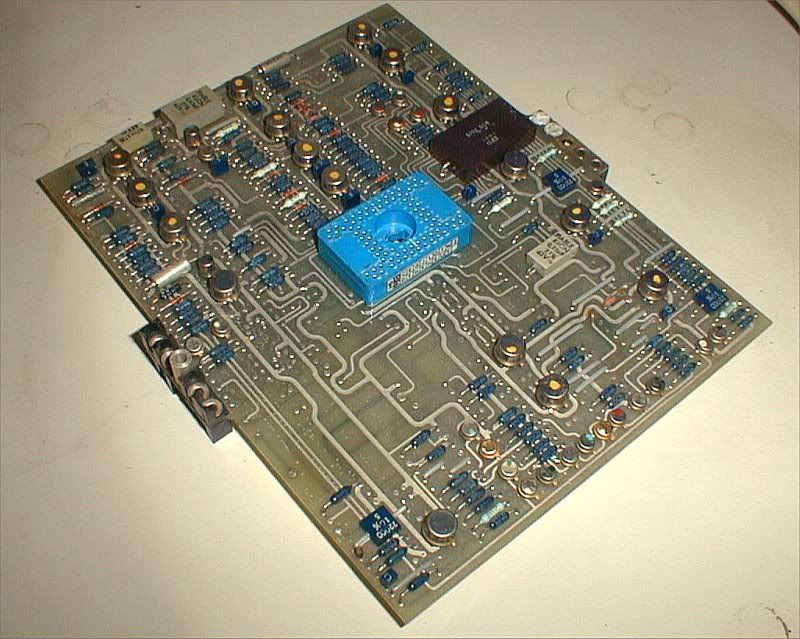
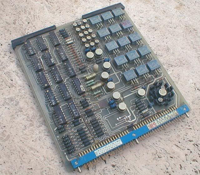
I have the rare privilege of actually having one of those rare "secret" air intake computers (AICU) sitting right next to my desk.
The circuit boards are mostly quite neat, with only the odd wire strap here and there.
However, the wiring of the unit itself, between the connectors, is a nightmare.
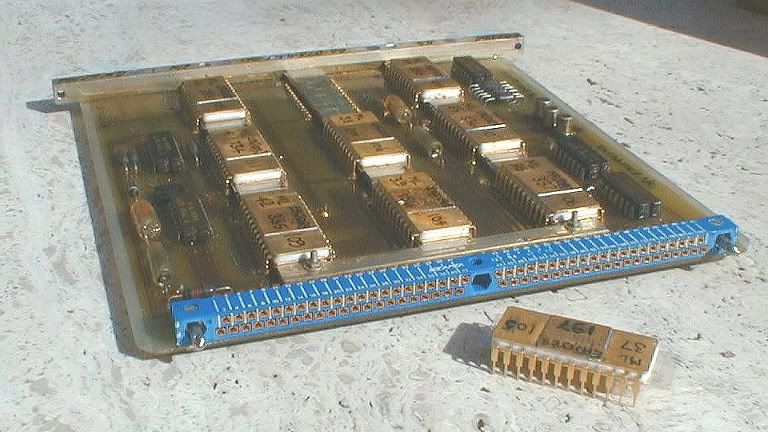
This is one of the PROM boards from the AICU, with one of the PROMs taken out of its socket. I have more photos, but will have to download those first, if anyone is interested.
Landroger
They're operational amplifiers, one per can!
Don't forget that all the computing in the AFCS computers was analog, not digital!
The vast majority were LM101As, with 741s in non-critical locations, and the odd LM108 for the really hiigh-precision stuff.
The board is actually a true antique, dating from one of the development aircraft.
We did not always do the kind of "butcher job" I described for the A/T. If there was enough time between major mods, the "firm" would redesign the board(s) and send us a new set, and the old ones would be binned... it made for better reliability. I kept a few as souvenirs.
I see you missed the real connector!
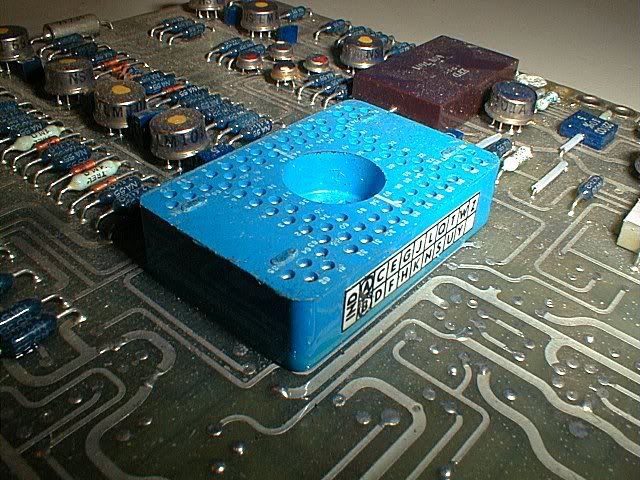
It's the big blue "thing" at the centre of the board, with no less than 80 pins.
This is the back of the card
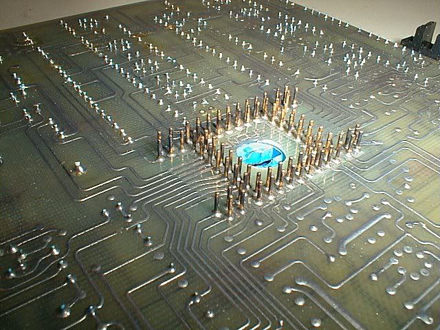
This is the central connector closer up
The idea wasn't bad at first sight.... it allowed stacking three boards on top of each other, so that many signals could pass from one board to another without any intermediate wiring. A small motherboard with a fourth conector would then take certain signals to other stacks, etc.
Another claimed advantage was that it made the board layout easier.
What was learned only gradually was that those connectors were hideously difficult to solder in place, and even more difficult to repair. Concorde was too far "on the way" to redesign the entire AFCS, so we learned to live with them, but the concept was abandoned afterwards.
The central connectors were only used for the analog boards ; the logic boards used more conventional 84-pin connectors on one side.
This is one of the logic boards.
Re the weight question, I would say M2dude 's answer is a lot better than mine, so ignore my remarks.....
Re the wiring, Concorde had about 300km of it.
IIRC the A380 Flying Hippo, which is vastly bigger, "only" has about 500km of wiring, and it seems a lot of that is the IFE (in-flight entertainment)
CJ
I have the rare privilege of actually having one of those rare "secret" air intake computers (AICU) sitting right next to my desk.
The circuit boards are mostly quite neat, with only the odd wire strap here and there.
However, the wiring of the unit itself, between the connectors, is a nightmare.
This is one of the PROM boards from the AICU, with one of the PROMs taken out of its socket. I have more photos, but will have to download those first, if anyone is interested.
Landroger
Quote:
| What little horrors hid inside those TO5 cans? |
Don't forget that all the computing in the AFCS computers was analog, not digital!
The vast majority were LM101As, with 741s in non-critical locations, and the odd LM108 for the really hiigh-precision stuff.
Quote:
| Apart from the fact that your board must be brand new - the track cutters and wire linkers hadn't got at it yet! |
We did not always do the kind of "butcher job" I described for the A/T. If there was enough time between major mods, the "firm" would redesign the board(s) and send us a new set, and the old ones would be binned... it made for better reliability. I kept a few as souvenirs.
Quote:
| What is interesting are the connections - only eight pins, as far as I can tell? We had 15/25/60 pin 'D' connectors or multi path, gold 'edge' connectors at least |
It's the big blue "thing" at the centre of the board, with no less than 80 pins.
This is the back of the card
This is the central connector closer up
The idea wasn't bad at first sight.... it allowed stacking three boards on top of each other, so that many signals could pass from one board to another without any intermediate wiring. A small motherboard with a fourth conector would then take certain signals to other stacks, etc.
Another claimed advantage was that it made the board layout easier.
What was learned only gradually was that those connectors were hideously difficult to solder in place, and even more difficult to repair. Concorde was too far "on the way" to redesign the entire AFCS, so we learned to live with them, but the concept was abandoned afterwards.
The central connectors were only used for the analog boards ; the logic boards used more conventional 84-pin connectors on one side.
This is one of the logic boards.
Re the weight question, I would say M2dude 's answer is a lot better than mine, so ignore my remarks.....
Re the wiring, Concorde had about 300km of it.
IIRC the A380 Flying Hippo, which is vastly bigger, "only" has about 500km of wiring, and it seems a lot of that is the IFE (in-flight entertainment)
CJ
25th Aug 2010, 17:15
permalink Post: 114
Nick Thomas
You are right on the button first time, the white paint finish is for heat reflection purposes. (When I worked at Filton/Fairford I remember reading a document showing the difference in 'hot soak' supersonic skin temperatures for white and black paint finishes. I'm afraid I can't remember any figures (it was a couple of million years ago ) but there was quite a surprising difference.
G SXTY
A hearty welcome to this thread, and thank you for your very kind comments; I'm sure I speak for all the Concorde people here when I say that it is quite amazing that so many people, both aviation professionals as well as more 'normal' people are so fascinated by what most of us still regard as the finest aircraft ever to grace the skies. Your comment about 'men with slide rules' is so totally correct; I still remember the No7 & No8 design offices at Filton, these were huge rooms filled with draughtsmen's boards, a horde of designers, all without a single computer in sight.
Dave Rowland is a total gentleman as well as being an extremely knowledgeable flyer too, and I know he (like most of us) would be happy to talk about Concorde until the cows come home.
ChristiaanJ
Aghhhh The dreaded AICU. I'd almost forgotten the innards, as you say the motherboard wiring was a total nightmare (good piece of knitting I seem to remember). As far as the 'secret' bit of the AICU, I think we all know that is a little bit of Concorde mythology, more science museum than secret really. Around ten years ago we had some fairly substantial modifications done to the units, due to component obsolescence. (I seem to remember that some of the components concerned were not only out of production, but only a few hundred examples existed worldwide}. I do remember that the power supply board, resolver demodulator boards as well as a couple of others were replaced with new ones using modern components. The modification did do wonders for component reliability.
The PROM board that you have the photo of reminds me of a really amusing anecdote, told to me by Dr Ted Talbot a while ago. Now Ted is one of the true fathers of the Concorde air intake, an absolute genius as well as being a really pleasant gentleman indeed. I'm pleased to say that when I met him a few months ago, he was still as sharp as ever in his advancing years.
The story goes like this: Much of the Concorde intake development trials were flown out of Tangiers and Casablanca, where cold stratospheric temperatures would be guaranteed. Software changes as a result of the flight trials had to be done in there and 'the field'. The way that you made programmed the PROMS was by 'burning' each individual logic gate with a 9v battery. It was highly specialised, as well as extremely tedious work indeed, as we can all well imagine. Anyway, in while he was in Tangiers with aircraft G-AXDN, Ted had arranged for a rather lovely looking lady to be flown out to do his ROM programming. The HS 125 from Filton landed at Tangiers and taxied in and parked next to Concorde, and all the flight test people were waiting on the tarmac. The door of the 125 opened and out stepped this really leggy lady. 'who's the bint then ?' pipes up a really gritty airframe fitter, in a really broad Bristol accent. Without giving it a thought, Ted chirps 'she's come to blow my proms'. The little fitter grunts, glares at Ted and comes out with 'typical office staff, you get all the ***ing perks'.
25th Aug 2010, 21:05
permalink Post: 118
Quote:
|
Originally Posted by
M2dude
Aghhhh The dreaded AICU. I'd almost forgotten the innards, as you say the motherboard wiring was a total nightmare (good piece of knitting I seem to remember).
|
Quote:
| As far as the 'secret' bit of the AICU, I think we all know that is a little bit of Concorde mythology, more science museum than secret really. |
The way I understood the story was that they tried to collect as many reasonably reliable spare AICUs for the last few delivery flights, so as not to have to suddenly cancel a flight.
The AICU was right at the top of the list of "unscheduled removals". IIRC the tea maker was second...
Quote:
| Around ten years ago we had some fairly substantial modifications done to the units, due to component obsolescence. (I seem to remember that some of the components concerned were not only out of production, but only a few hundred examples existed worldwide}. I do remember that the power supply board, resolver demodulator boards as well as a couple of others were replaced with new ones using modern components. The modification did do wonders for component reliability. |
Quote:
| Much of the Concorde intake development trials were flown out of Tangiers and Casablanca, where cold stratospheric temperatures would be guaranteed.Software changes as a result of the flight trials had to be done in there and 'the field'. The way that you made programmed the PROMS was by 'burning' each individual logic gate with a 9v battery. It was highly specialised, as well as extremely tedious work indeed, as we can all well imagine. |
"... 'burning' each individual logic gate with a 9v battery." I believe you, thousands wouldn't... Didn't you have at least some sort of programming unit?
I went through a similar exercise around 1976, but at that time at least we had a programming "suitcase", that let you copy the original in RAM, modifiy bit-by-bit with a keyboard, then 'burn' the PROM (or EPROM, by then) 'automatically'. Still took half the night....
Funny in a way how these things have stuck in our memories... But then, yes, Concorde was unique.
I've said this elsewhere, but I don't mind repeating it... in those days, there were two programmes to be part of. One was Apollo, the other was Concorde. And I've had the chance to be part of one of them.
CJ
25th Aug 2010, 21:52
permalink Post: 121
ChristiaanJ
Ah now, those boards are actually very good looking boards. I particularly like the PROM board and although I know about the programming of those, it is only at third hand. I certainly had to install many of those PROMS that had been specially 'burned' in Milwaukee, to overcome a particular problem.
I'm a bit embarrassed about missing that multi pin socket on the AICU board.
I somehow thought it was a specific function chip or a development test socket. Some of those used to appear and remained on some of our boards.
I'm not surprised about the massive cost of replacing certain boards in the later years. Some of those components would have been made of unobtainium long before the millenium. And I just noticed DozyWannabe's question about core memory. I guess it would have been core, because the 8Kb memory boards I spoke about, from the early CT Scanners, were Data General core memory, with a cycle time of 800usec.
Although with four way interleaving, we could get that down to the read cycle time of 200usec!!

I freely admit I am staggered at how capable were Concorde's electronics - indeed how capable was the whole aeroplane - despite their rather ..... fundamental nature. My respect for everyone involved in the project increases with every post to this thread.
Roger.
I'm a bit embarrassed about missing that multi pin socket on the AICU board.
I somehow thought it was a specific function chip or a development test socket. Some of those used to appear and remained on some of our boards.
I'm not surprised about the massive cost of replacing certain boards in the later years. Some of those components would have been made of unobtainium long before the millenium. And I just noticed DozyWannabe's question about core memory. I guess it would have been core, because the 8Kb memory boards I spoke about, from the early CT Scanners, were Data General core memory, with a cycle time of 800usec.
Although with four way interleaving, we could get that down to the read cycle time of 200usec!!
I freely admit I am staggered at how capable were Concorde's electronics - indeed how capable was the whole aeroplane - despite their rather ..... fundamental nature.
My respect for everyone involved in the project increases with every post to this thread.
Roger.
25th Aug 2010, 23:04
permalink Post: 123
Quote:
|
Originally Posted by
Landroger
I'm a bit embarrassed about missing that multi pin socket on the AICU board.
I somehow thought it was a specific function chip or a development test socket. Some of those used to appear and remained on some of our boards.
|
Could be Autostab, Lateral Autopilot or Trim, since they all used exactly the same technology, board size, etc.
Looking at the board, I think it's 'Lat A/P' but I can't be certain.
No excuse needed about missing the "central connector" !
It was really a "one-off" feature, invented by Bendix, and abandoned afterwards. I'm not even sure the early A300B AFCS computers, that used much of the Concorde technology, still had them.
Quote:
| I just noticed DozyWannabe's question about core memory. I guess it would have been core... |
CJ
5th Nov 2010, 11:56
permalink Post: 663
I have to admit that some of the subsonic fuel burn figures for Concorde were truly eye watering, and without massive engine and airframe modifications there was precious little in service that could be done to improve things. Paradoxically improvements to the
supersonic
efficiency of the powerplant were easier to implement, and several modifications were implemented, tried or proposed to improve fuel burn:
Way back in the late 1970's we did a major modification to the intakes that increased capture area by 2.5% and gave us typically a 1.6% improvement in trans-Atlantic fuel burn, and although this was our biggest performance improvement modification, there were more:
The famous elevon and rudder trailing edge extension modifications (that due to poor design, produced in later life the water ingress induced honeycomb failures) together with the re-profiled fin leading edge modification, I never saw the performance gains quantified (anyone have any ideas?).
Can anyone here remember the riblet trial? In the mid 1990's Airbus supplied 'stick on' plastic riblets, applied to various areas on the under-side of the wing on G-BOAG. These riblets had very fine undulations moulded into the surface; the idea being that as the air flowed through and around the riblet patches, boundary layer turbulence, and hence induced drag would be reduced. Now, the performance gains (if any) were never quantified, mainly because the riblet patches either peeled off or the surface deteriorated with the continuous thermal cycle. (I was over in JFK when the aircraft first arrived after having the riblets fitted, and as the crew were trying to proudly show me these amazing aerodynamic devices, they were sadly embarassed, as several had dissapeared in the course of a single flight).
There was one modification, proposed by Rolls Royce in the late 1990's that did have quite a lot of potential; this was to increase the engine N1 by around 1.5%. This would have had the effect of increasing engine mass flow and therefore reducing the drag inducing spill of supersonic air over the lower lip of the intake. Depending on the temperature, the performance gains were in the order of a 1.5% improvement in fuel burn at ISA Plus upper atmosphere temperatures ('normal' LHR-JFK) to none at all at significant ISA Minus temperatures (LHR -BGI). The modifacation had been trialed on G-BBDG before her retirement in the early eighties, and was proven in terms of performance enhancement and engine stability. In order to keep TET at the pre-modification level, there was a small increase in N2 commanded also. (The higher N1 required an increase in primary nozzle area, reducing TET). The main reason for the modification not being implemented was one of cost; The Ultra Electronics Engine Control Units were analog units, and the modification was a simple replacement of two resistors per unit. However because ultimate mass flow limitation was also controll by the digital AICU (built by British Aerospace Guided Weapons Division) the cost of getting a software update for this exremely 'mature' unit was found to be prohibitive.
A certain 'brainy' SEO and myself were working on a modification to improve fuel burn on ISA minus sectors. The idea was to force the autopilot, in Max Cruise at low temperatures only , to fly the aircraft close to Mmo, rather than at Max Cruise speed of Mach 2 - 2.02; this would have given us gains of up to 1%, depending on the temperature. The basic electronics involved for the modification were relatively straightforward, but it was never pursued due to the complexity of dealing with temperature shears and the cost of certification.
Dude
Last edited by M2dude; 5th Nov 2010 at 15:49 .
27th Nov 2010, 18:30
permalink Post: 798
Quote:
|
Originally Posted by
CAAAD
Dude - I think basic engine hardware was in good supply.... We have a couple of Olympus intake blanks which we find absolutely perfect for gardening with our aged knees.
|
Not to mention the vast quantity of spare compressor and turbine blades and stator vanes, spread far and wide after the end-of-service, through the spare parts auctions.
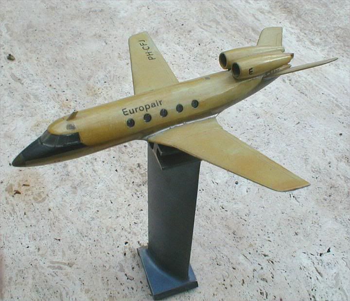
(The model is a design that was part of my engineering studies - late '60s - but the compressor vane is real Concorde.)
Quote:
| ....but there were concerns about the control amplifier component availability. |
M2dude and myself already have mentioned the same problem with the AICU (air intake control computer) in this thread.
People do only rarely realise how rapidly technology was changing in the early Concorde days, and how difficult it was to procure components that sometimes were already obsolete when Concorde entered service.
CJ
7th Dec 2010, 22:18
permalink Post: 840
Wow thanks a lot M2Dude for your diagram.
I'm wonder that did Concorde has a neutal of stable stability? Did the elevon work out the same job to produce the stability like the elevator and stabilizer?
Also, I have read your post and wonder why when the temp fall below ISA-7, the AICU order the N1 to decrese?
And the final question. In the early concorde, does the pilot has ability to select the amount of afterburn thrust by rotate the area knob is that right? and why the airline remove it?
Thanks for your reply.
Best Regards
8th Dec 2010, 18:05
permalink Post: 841
Landroger
The great thing about the OLY593 was the high specific thrust (in relative terms the Olympus is a tiny, compact design), it's growth potential/high potential mass flow. A bypass engine is not really ideal for supersonic cruise, and given what was available in terms of two-spool turbojets in the 1960s, the Olympus was the obvious choice for both the TSR-2 and Concorde alike. As far as for ships and power stations, well a turbojet is always going to be favourite, as all the gas energy is contained in the jet efflux; this can be efficiently transferred to the load in question by a gearbox coupled to the HP spool.
howiehowie93
Well the 593 did require a primary nozzle to match N1 against N2, bur apart from that she was a study of deceptive simplicity and elegance.
No mate, generally BI-HEX AF.
This really is fascinating stuff Howie, thank you. As I alluded to a few pages back, the primary nozzle on the OLY593 opened in response to the rising P7, kind of 'after the horse has bolted' in a way. To maintain the correct scheduled value of N1, the control system set, via a needle valve, a finite ratio between P7 and P3. As reheat lit as P7 attempted to rise it upset this ratio and the primary nozzle was opened in order to restore the aforementioned ratio. (Nozzle opens, P7 falls). When reheat was cancelled the opposite happened, and the nozzle closed sharply to prevent N1 overspeed.
Tom355UK
Glad you are enjoying our thread, and thank you for your kind words. (But apologies to your good lady wife though
 ).
).
Jeepers Tom that is one hell of a question. Assuming there was a market for such a venture (personally not sure right now) I think you are looking at BILLIONS of $, and for this reason alone I think you'd find that a multi-national/continental effort would be required. There is little doubt that technology is not the major barrier here, but economics and political will. (Nice thought though, I do agree).
As far as a powerplant goes, well the PW5000 is a really superb engine, although well down on the thrust requirement for an 'NG' SST. More likely I would have thought would be e development of the Olympus, there was/is still such an enormous amount of potential in this basic design. (But who knows, this is all pure speculation anyway).
And have no fears about posting here Tom, most of us are quite happy to answer away (We've said before that there is no such thing as a stupid question; you are most welcome here
).
DavvaP
It really did not matter what airframe we used for the test flight; the sole purpose was just to find out just what effect (if any) the tank liners had on the performance of the fuel system. (The handsome chap who you see on TV most, installing the liners, Mr Marc Morley left BA and now resides in Australia).
I am honoured to say that I was lucky enough to be onboard G-BOAF for that flight from LHR-BZZ and as far as I could tell, the liners had no impact whatsoever. One amusing part of the flight was when we deliberately allowed tank 3 to run dry and see just what the indicated fuel quantity was as #3 engine flamed out (we were subsonic at this point of course). The gauge slowly crept down (in order for the tank to to run dry, the tank 7 & 8 transfer pumps were switched off) and we all watched in eager anticipation/dread....... as the counters reached zero weeeeeee... the engine flamed out. I am being completely honest here, the engine wound down EXACTLY at
ZERO
indicated contents).
part of the flight was when we deliberately allowed tank 3 to run dry and see just what the indicated fuel quantity was as #3 engine flamed out (we were subsonic at this point of course). The gauge slowly crept down (in order for the tank to to run dry, the tank 7 & 8 transfer pumps were switched off) and we all watched in eager anticipation/dread....... as the counters reached zero weeeeeee... the engine flamed out. I am being completely honest here, the engine wound down EXACTLY at
ZERO
indicated contents).
Those 7 aircraft really did look magnificent I know, it was just sad as to the reason they were all lined up there.
Mr.Vortex
Well she was a delta without a tailplane, so the short answer is 'yes', but remember that we used fuel to move the CG backwards and forwards for long term trimming.
OK, this is a little complicated, so bear with me. The intake had a finite limit, in terms of the mass flow that it could deliver to the engine and so an automatic N1 limitation signal was transmitted from the intake 'box' (the AICU) to the engine 'box' (the ECU) full time above Mach 1.6. Now this limitation was referenced against TEMPERATURE compensated N1, (
N1/
\xd6
q)
and at normal ISA temperatures this limit was above the 'normal' 101.5% N1 running line. (The lower the temperature, the lower the effective limit became). At ISA -7 the limit now became less than 101.5% N1, and so the demanded value of N1 was reduced to this value. But this limit signal was always there, it's just that at normal temperatures it was effectively ignored by the ECU. If this limitation signal failed for any reason, the AICU would detect this by way of the ramp angle becoming uncomfortably close to it's MINIMUM variable limit (this limit was scheduled as a function of intake local Mach number) and an amber light would illuminate on the associated N1 gauge, along with an amber INTAKE master warning would illuminate (plus an audible 'BONG' from the audio warning system). The only course of action was to manually reduce throttle setting away from the Mach 2 norm of maximum, in order to reduce N2, and consequently N1 and mass flow demand. There was in intake pressure ratio indicator at the top of the intake control panel that would show where the power setting would have to be set to. It was an indirect indication of intake shock geometry.
This manual N1 datum reset control was only used during flight test trials into just how much N1 would have to be controlled/reduced at low temperatures in order to give optimim intake geometry. It had absolutely nothing to do with afterburner/reheat and had no place in the production aircraft as all the research was complete
Best regards to all
Dude
Quote:
| Which brings me to my questionette - given that Bristol-Siddley created the original design when jet travel was still quite novel, what was it about the Olympus that made it so capable in so many guises and for so long? Not only Concorde of course, but TSR2, warships and fixed electrical generators. |
howiehowie93
Quote:
| The Olympus - nowt ! Two Spools and a Fuel Valve thats your lot. nothing to go wrong and being an Aeroderivative all the ancillary equipment is either bolted on underneath or away from the engine outside the enclosure. |
Quote:
| Was it all still BSF on the 593? |
Quote:
| oh ! I forgot about the Hot Shot; when I was ground running installed RB199's there was no jump in TBT/T7, you couldn't sense it fire either, the only feel was either the Reheat lighting off with a big roar or the engine going quiet as the Nozzle opened up until the MECU noticed it hadn't lit and closed it again sharpish. |
Tom355UK
Quote:
| How much would it cost, do you think, that IF EADS really wanted to, using a combination of all the knowhow gained through L'Oiseau Blanc and their current lineup could they produce a 'Concorde NG'? Most importantly, would there be a market for such a beast (at the right price)? |
).
Jeepers Tom that is one hell of a question. Assuming there was a market for such a venture (personally not sure right now) I think you are looking at BILLIONS of $, and for this reason alone I think you'd find that a multi-national/continental effort would be required. There is little doubt that technology is not the major barrier here, but economics and political will. (Nice thought though, I do agree).
As far as a powerplant goes, well the PW5000 is a really superb engine, although well down on the thrust requirement for an 'NG' SST. More likely I would have thought would be e development of the Olympus, there was/is still such an enormous amount of potential in this basic design. (But who knows, this is all pure speculation anyway).
And have no fears about posting here Tom, most of us are quite happy to answer away (We've said before that there is no such thing as a stupid question; you are most welcome here
).
DavvaP
Quote:
| Ok, so my question is - BA had to use an airframe as a test for the modifications. However, the choice of airframe seemed a strange one to me, BOAF - which I previously thought to be one of the youngest and best airframe they had (m2dude you explained that BOAF and BOAG weighed less than the previous models). So, why would BA use one of their best airframes, rather than use perhaps the most worn out of their fleet? |
I am honoured to say that I was lucky enough to be onboard G-BOAF for that flight from LHR-BZZ and as far as I could tell, the liners had no impact whatsoever. One amusing
part of the flight was when we deliberately allowed tank 3 to run dry and see just what the indicated fuel quantity was as #3 engine flamed out (we were subsonic at this point of course). The gauge slowly crept down (in order for the tank to to run dry, the tank 7 & 8 transfer pumps were switched off) and we all watched in eager anticipation/dread....... as the counters reached zero weeeeeee... the engine flamed out. I am being completely honest here, the engine wound down EXACTLY at
ZERO
indicated contents).
Those 7 aircraft really did look magnificent I know, it was just sad as to the reason they were all lined up there.
Mr.Vortex
Quote:
| I'm wonder that did Concorde has a neutal of stable stability? Did the elevon work out the same job to produce the stability like the elevator and stabilizer? |
Quote:
| Also, I have read your post and wonder why when the temp fall below ISA-7, the AICU order the N1 to decrese? |
Quote:
| And the final question. In the early concorde, does the pilot has ability to select the amount of afterburn thrust by rotate the area knob is that right? and why the airline remove it? |
Best regards to all
Dude
21st Dec 2010, 13:04
permalink Post: 922
quote:Rolls Royce did some analysis on the flight, and were amazed at how well the propulsion systems coped with some of the temperature sheers that we encountered, sometimes 4 to 5 deg's/second. They said that the prototype AFCS had been defeated by rises of only 0.25 deg's/second ).unquote
Just for the record, the intake control system was designed to cope with a temperature shear of 21 deg C in one mile (about 3 seconds)
quote:Not meaning to go off onto a (yet another) tangent; Negative temperature shears, very common at lower lattidudes, always plagued the development aircraft; you would suddenly accelerate, and in the case of a severe shear, would accelerate and accelerate!! (Your Mach number, quite naturaly, suddenly increased with the falling temperature of course, but because of the powerplant suddenly hitting an area of hyper-efficiencey, the A/C would physically accelerate rapidly, way beyond Mmo). Many modifications were tried to mitigate the effects of severe shears, in the end a clever change to the intake control unit software fixed it. (Thanks to this change the production series A/C would not be capable of level flight Mach numbers of any more than Mach 2.13, remembering that Mmo was set at 2.04).unquote
Not temperature shears, and not AICU modifications (which I see has been discussed in a later posting). But back to the 'shears':
Most of Concorde's flight testing was, naturally, done out of Toulouse and Fairford, i.e. into moderate latitude atmospheres where the tropopause is normally around 36,000 ft so that the supersonic flight testing was done in atmosphers where the temperature doesn't vary with altitude. The autopilot working in Mach hold would see an increase in Mach and apply up elevator to reduce IAS and recover the macg setting. But at the lower latitudes around the equator the atmosphere is different in its large scale characteristics. In particular the tropopause is much, much higher and can get as high as 55,000 ft. Nobody had been up there to see what it was like! Now when the A/P applied up elevator to reduce IAS it went into a region of colder air. But the speed of sound is proportional to air temperature, so as the aircraft ascended the IAS dropped alright but since the ballistic (true) velocity of the aircraft takes a while to change and since the speed of sound had dropped the Mach number was increased, so the A/P seeing this applied more up elevator and the aircraft went up and the speed of sound dropped and ........
Like solving crossword clues, the answer is obvious once you have spent some time finding it!
This phenomenon rather than temperature shears (encountered mainly over the tops of Cb clouds) was the reason for the autopilot modifications which included that clever use of autothrottle (I can use that adjective since it was my French colleagues that devised it)
And before anyone asks; yes, the same problem would relate to subsonic aircraft operating in Mach hold driven by the elevators and flying below the tropopause, but:
a) Subsonic aircraft are old ladies by comparison with Concorde in that they fly at only half the speed. At Concorde velocities even modest changes in pitch attitude can generate some pretty impressive rates of climb or dive!
b) Subsonic aircraft are normally constrained by ATC to fly at fixed flight levels - the use of elevator to control Mach number is not really an option - you have to use an autothrottle.
There was that other problem, also described in later postings, where the aircraft regularly 'rang the bell' when passing through the Vmo/Mmo corner in the lower latitudes, but this was simply due to the additional performance one got in these ISA minus conditions in comparison to the temperatures encountered around the same corner in higher temperatures.
Anyway, the flight test campaign got me my first sight of sunrise over the Arabian desert and my first trip to Asia, so it goes into my Concorde memory bank.
22nd Dec 2010, 21:30
permalink Post: 952
Quote:
|
Originally Posted by
ChristiaanJ
The early development aircraft still had an analogue system, which proved all too soon to be inadequate, so, at a very late stage, it was replaced by a digital system (one of the rare digital systems on Concorde).
|
CliveL
23rd Dec 2010, 08:54
permalink Post: 961
CliveL
Tee hee, can't get away with anything here anymore Clive
Yes, of course (as ever
 ) you are correct; it was technically a hybrid system: The servo loops, in terms of ramp and spill door demand signals and resolver position feedback signals etc. DID use conventional analogue drive and servo amplifiers within the AICU, it was the massive arithmetic computation UP-STREAM of these that was digital. I always used to like to refer to the AICS as 'an analog front end with a digital brain'. But that's just me
.
) you are correct; it was technically a hybrid system: The servo loops, in terms of ramp and spill door demand signals and resolver position feedback signals etc. DID use conventional analogue drive and servo amplifiers within the AICU, it was the massive arithmetic computation UP-STREAM of these that was digital. I always used to like to refer to the AICS as 'an analog front end with a digital brain'. But that's just me
.
But as you say Clive, none of the control law sophistication (including the synthesising the intake face total pressure and local Mach numbers from mainline aircraft raw air data) would have been possible using analog computation.
Best regards
Dude
Quote:
| I've noticed that several postings refer to the production AICU as a 'digital' control system. Strictly speaking it wasn't; it was a hybrid digital/analogue system where the inner dynamic control loops (the closed loop part) were analogue systems operating to maintain limits defined by the digital arithmetic processors. This allowed us to have quite sophisticated control 'laws' which would have been next to impossible with a pure analogue system. |
Yes, of course (as ever
) you are correct; it was technically a hybrid system: The servo loops, in terms of ramp and spill door demand signals and resolver position feedback signals etc. DID use conventional analogue drive and servo amplifiers within the AICU, it was the massive arithmetic computation UP-STREAM of these that was digital. I always used to like to refer to the AICS as 'an analog front end with a digital brain'. But that's just me
.
But as you say Clive, none of the control law sophistication (including the synthesising the intake face total pressure and local Mach numbers from mainline aircraft raw air data) would have been possible using analog computation.
Best regards
Dude
6th Jan 2011, 19:02
permalink Post: 1076
Quote:
|
Originally Posted by
M2Dude
, it was just a shame that's all, that the Type 28 never fully lived up to its promise and potential.
One little unique point about 102; she flew with a different intake control system to any other Concorde, being an 'improved' Ultra Electronics analog system. (Although the intake itself was aerodynamically the same as the later aircraft). Never really understood why our French friends chose this particular path with this aircraft. (Perhaps CliveL can shed some light on this??) |
One of the things I like about this thread is the way in which it reminds me of things I had forgotten about the design phase - or in this case informs me of things I maybe never knew! I just do not remember any improved Ultra AICU design. So far as the French 'choice' on the matter, they probably weren't given one. Like the rear fuselage alterations referred to in another posting , it was all a matter of timing. 102 came after 101 so 102 got the lengthened rear fuselage (which was done to improve the 'area rule' distribution and gave about 2.5% drag reduction). We (BAC) were going to do the AICU development so it made sense for 101 to get the early hybrid units. [If you were cynical you might equally say that there was no way we were going to let AS have them first!].
CliveL
6th Jan 2011, 21:06
permalink Post: 1077
CliveL
, You wrote:
"We (BAC) were going to do the AICU development so it made sense for 101 to get the early hybrid units. [If you were cynical you might equally say that there was no way we were going to let AS have them first!]."
Is that a typo and did you mean "it made sense for 102 to get the early hybrid units."?
I think M2dude had more fun with the air intakes at the time than I had with the AFCS, although getting MAX CLIMB and MAX CRUISE to work was, to say the least, "interesting".
Christian
7th Jan 2011, 11:06
permalink Post: 1078
ChristiaanJ, you wrote:Is that a typo and did you mean "it made sense for
102
to get the early hybrid units."?
No. it wsn't a typo, but you may have been misled by my use of 'hybrid' by which I meant the final AICU version which most people describe as digital.It had digital law generation but analogue servo control loops. We were responsible for development of the AICU 'laws' and with Fairford being less than an hours drive from Filton it was far more convenient to do the flight testing out of Faiford so that results could be evaluated rapidly and the next day's flight test sequence planned.
CliveL
13th Jan 2011, 09:45
permalink Post: 1082
atakacs
Really an answer for CliveL, but I'll have a go. The short answer to your question is 'oh yeah, big time'. Total temperature varies with the SQUARE of Mach number and static temperature. Depending on the height of the tropopause itself as well as other local factors, there can be little or no significant variation of static temperature between FL600 and FL700. The 400\xb0K (127\xb0C) Tmo limit was imposed for reasons of thermal fatigue life, and equates to Mach 2.0 at ISA +5. (Most of the time the lower than ISA +5 static air temperatures kept us well away from Tmo). In a nutshell, flying higher in the stratosphere gains you very little as far as temperature goes. (Even taking into account the very small positive lapse above FL 650 in a standard atmosphere). As far as the MAX SPEED bit goes, Concorde was as we know flown to a maximum of Mach 2.23 on A/C 101, but with the production intake and 'final' AICU N1 limiter law, the maximum achievable Mach number in level flight is about Mach 2.13. (Also theoretically, somewhere between Mach 2.2 and 2.3, the front few intake shocks would be 'pushed' back beyond the lower lip, the resulting flow distortion causing multiple severe and surges).
On C of A renewal test flights (what I always called the 'fun flights') we DID used to do a 'flat' acceleration to Mach 2.1 quite regularly, as part of the test regime, and the aircraft used to take things in her stride beautifully. (And the intakes themselves were totally un-phased by the zero G pushover that we did at FL630). This to me was an absolute TESTAMENT to the designers achievement with this totally astounding aeroplane , and always made me feel quite in awe of chaps such as CliveL.
Well the maximum altitude EVER achieved in testing was I believe by aircraft 102 which achieved 68,000'. As far as the second part of your question goes, not to my knowledge (gulp!!) but perhaps CliveL can confirm.
Shaggy Sheep Driver
So glad you are enjoying the thread, and absolutely loved the description of your flight in OAD and your photo is superb. I don't think it is possible to name a single other arcraft in the world that could be happily flown hands off like this, in a turn with 20\xb0 of bank at Mach 2. (One for you ChristiaanJ; The more observant will notice that we are in MAX CLIMB/MAX CRUISE with the autothrottle cutting in in MACH HOLD. Oh, we are in HDG HOLD too ).
).
Now for your question
A very good question. The anti-skid system used a fixed simulated nose wheel rolling speed Vo signal as soon as the undercarriage was down and locked, this was confirmed by the illumination of the 8 'R' lights on the anti-skid panel. The illumination of these lights confirmed that there was full ant-skid release from the relevant wheel, due to there being of course zero output initially from the main gear tachos but this simulated Vo output from the nose gear tacho. The Vo signal therefore ensured that the aircraft could not be landed 'brakes on' (all the main wheels think they are on full skid) and that there was anti-skid control pending lowering of the nose-wheel. As the main wheels spin up on landing, their tacho outputs now start to back off the Vo signal, and braking can commence. As the nose leg compresses, the Vo signal is removed and the Nose-wheel tachos(their were 2 wired in parallel) spin up, their output will now replace the Vo signal, and full precise anti skid operates.
As far as your air conditioning question goes, you needed an external air conditioning truck to supply cabin air on the ground. Not needed in the hangars of course, but come departure time if these trucks were not working, then the cabin could become very warm/hot place indeed (depending on the time of year). Oh for an APU
Best regards
Dude
Quote:
| Just wondering was that the maximum speed "in" the design ? I understand that "the higher & the colder = the faster" was the key to the performance and that the Mach +/- 2.0 cruise was implied by limiting altitude to FL 600 in order to mitigate cabin depressurization consequences. I guess there where also thermal issues but was, say, Mach 2.2 @ FL700 "warmer" than Mach 2.0 @ FL600 ? |
Really an answer for CliveL, but I'll have a go. The short answer to your question is 'oh yeah, big time'. Total temperature varies with the SQUARE of Mach number and static temperature. Depending on the height of the tropopause itself as well as other local factors, there can be little or no significant variation of static temperature between FL600 and FL700. The 400\xb0K (127\xb0C) Tmo limit was imposed for reasons of thermal fatigue life, and equates to Mach 2.0 at ISA +5. (Most of the time the lower than ISA +5 static air temperatures kept us well away from Tmo). In a nutshell, flying higher in the stratosphere gains you very little as far as temperature goes. (Even taking into account the very small positive lapse above FL 650 in a standard atmosphere). As far as the MAX SPEED bit goes, Concorde was as we know flown to a maximum of Mach 2.23 on A/C 101, but with the production intake and 'final' AICU N1 limiter law, the maximum achievable Mach number in level flight is about Mach 2.13. (Also theoretically, somewhere between Mach 2.2 and 2.3, the front few intake shocks would be 'pushed' back beyond the lower lip, the resulting flow distortion causing multiple severe and surges).
On C of A renewal test flights (what I always called the 'fun flights') we DID used to do a 'flat' acceleration to Mach 2.1 quite regularly, as part of the test regime, and the aircraft used to take things in her stride beautifully. (And the intakes themselves were totally un-phased by the zero G pushover that we did at FL630). This to me was an absolute TESTAMENT to the designers achievement with this totally astounding aeroplane , and always made me feel quite in awe of chaps such as CliveL.
Quote:
| Also wondering what was the max altitude ? Was high altitude stall (for the lack of a better word) ever experimented during tests or training ? |
Shaggy Sheep Driver
So glad you are enjoying the thread, and absolutely loved the description of your flight in OAD and your photo is superb. I don't think it is possible to name a single other arcraft in the world that could be happily flown hands off like this, in a turn with 20\xb0 of bank at Mach 2. (One for you ChristiaanJ; The more observant will notice that we are in MAX CLIMB/MAX CRUISE with the autothrottle cutting in in MACH HOLD. Oh, we are in HDG HOLD too
).
Now for your question
Quote:
| I understand that the anti-skid used a rotational reference from the unbraked nosewheels to compare to the rotation of the mains, and that with gear down in the air a substiute nose-wheel referance is supplied which, because the mains are not yet rotating, allows the anti-skid to keep the brakes off. But what happens when the mains touch down with the nose wheels still high in the air? What (if anything) inhibits wheel braking until the nosewhels are on the ground (and therefore rotating)? |
As far as your air conditioning question goes, you needed an external air conditioning truck to supply cabin air on the ground. Not needed in the hangars of course, but come departure time if these trucks were not working, then the cabin could become very warm/hot place indeed (depending on the time of year). Oh for an APU
Best regards
Dude
13th Jan 2011, 11:10
permalink Post: 1083
Quote:
|
Originally Posted by
M2Dude
Really an answer for CliveL, but I'll have a go. The short answer to your question is 'oh yeah, big time'. Total temperature varies with the SQUARE of Mach number and static temperature. Depending on the height of the tropopause itself as well as other local factors, there can be little or no significant variation of static temperature between FL600 and FL700. The 400\xb0K (127\xb0C) Tmo limit was imposed for reasons of thermal fatigue life, and equates to Mach 2.0 at ISA +5. (Most of the time the lower than ISA +5 static air temperatures kept us well away from Tmo). In a nutshell, flying higher in the stratosphere gains you very little as far as temperature goes. (Even taking into account the very small positive lapse above FL 650 in a standard atmosphere). As far as the MAX SPEED bit goes, Concorde was as we know flown to a maximum of Mach 2.23 on A/C 101, but with the production intake and 'final' AICU N1 limiter law, the maximum achievable Mach number in level flight is about Mach 2.13. (Also theoretically, somewhere between Mach 2.2 and 2.3, the front few intake shocks would be 'pushed' back beyond the lower lip, the resulting flow distortion causing multiple severe and surges).
On C of A renewal test flights (what I always called the 'fun flights') we DID used to do a 'flat' acceleration to Mach 2.1 quite regularly, as part of the test regime, and the aircraft used to take things in her stride beautifully. (And the intakes themselves were totally un-phased by the zero G pushover that we did at FL630) |
As usual Dude you beat me to it! I really must give up having another life

As Dude says, the 'cruise' condition was set by the aircraft specification for transatlantic range on an 85% (ISA +5) day and the chosen mach Number was 2.0 (of which more anon). This gives a Total Temperature of 400.1 deg K. [Dude, I know your pipe-smoking thermodynamicist and he was having you on - he is quite capable of memorising the square/square root of 407.6 or whatever!]
To give margins for sudden changes in ambient temperature (we had to cater for a 21 deg change in one mile) the Mmo was set at 2.04 which matches 400 degK at ISA +1. In theory then we could have flown faster than our chose Mmo at anything colder than this, but there are two limits:
1) The object is not to fly as fast as you can but to fly with minimum miles/gallon. If you have a nice cold day and enough thrust to go either faster or higher which do you choose? For best specific range you go higher every time.
2) The thing that everyone forgets is that civil aircraft have to have margins around their authorised envelope. In Concorde's case these were set principally by the intake limits and engine surge.
Dude also says quite correctly that 101 flew to 2.23M but the production aircraft was limited to 2.13M. Now you may not believe this, but 101 could fly faster than the production aircraft because she (101) leaked like a sieve!.
I doubt I will get away with that without some explanation

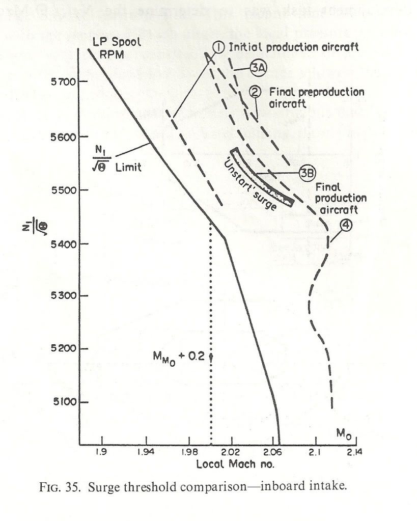
Once you get past a certain Mach Number the airflow into the intake is fixed. The performance (intake pressure recovery and engine face flow distortion) then depends on how this air is shared between the engine and the throat 'bleed'. This bleed was ducted over the engine as cooling air and then exhausted (in principle) throught the annulus formed between the expanding primary jet and the fixed walls of the con-di nozzle. But if you took, or tried to take, more bleed air the intake pressure recovery went up and the primary jet pipe pressure went up with it. This meant that the primary jet expanded more and squeezed the available annulus area which restricted the amount of bleed air one could take.
Obviously if there are alternative exit paths between intake and final nozzle then you can take more bleed air off and the engine face flow distortions will benefit along with the surge margin. 101 was fairly 'leaky' in this respect, particularly around the thrust reverser buckets on the original nozzle design. This meant that 101's intake distortions were lower than the production aircraft so she could fly faster without surge - at least with the first attempt at intake control 'laws'. We managed to tweak most of the margin back eventually. Engine bay leaks were good for surge margin but VERY bad news for m.p.g.!
Here are a couple of diagrams to show what I mean. the first shows the surge lines for the various aircraft variants and also the N1 limiter Dude was talking about. NB: the X-axis is LOCAL Mach Number not freestream. The difference comes from the compression of the underwing flow by the bit of the wing ahead of the intake. Mmo + 0.2 is shown
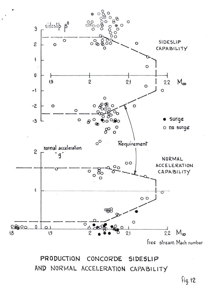
 ">The next shows the surge free boundaries in sideslip and normal acceleration. You can see the zero 'g' capability Dude was enthusing over.
 ">
">
As for 'high speed stall', I don't think we ever contemplated trying it! Our requirements in 'g' capability were defined and that was it. Besides, the aircraft would fly like the proverbial stone-built outbuilding at those sorts of conditions so I don't think one would have been able to get anywhere near a stall in the conventional sense. Stall as commonly defined for subsonics (deterrent buffet) might have been another matter, but I don't remember anything.
Cheers
Last edited by CliveL; 13th Jan 2011 at 11:17 . Reason: additional explanation
18th Jan 2011, 16:56
permalink Post: 1126
Quote:
|
Originally Posted by
M2Dude
I confess. I'm afraid that I did intentially use that awful pun (sorry
 ).
).
|
Yes, the 188 was welded stainless and as you said, manufacturing was a pain. I didn't work on that aircraft myself, but one reported episode in the flight test programme is worth a digression off topic. Dialogue (maybe that should be monologue) between aircraft and FT control:
t = 0
Godfrey Auty (test pilot): "Mach ... port engine flamed out"
Silence from ground
t = 10secs
G.A.: "Mach .... starboard engine flamed out"
Silence from ground
t= 15 secs
G.A. "Well for Chrissake say something, even if it's only goodbye!"
Luckily the restart drills worked

After those AICU problems the boss came to see me (I was running the S&C section at the time) and said "Your blokes are doing dynamic simulation of aircraft response (on ANALOGUE computers!), do you think they could simulate the 188 intake control system?". To which of course there is only one answer possible, but that is how the two aerodynamicists who did most of the pioneering work on the Concorde AICU came to work together - Derek Morriss from the 188 project and Terry Brown from the S&C group. And boy were we lucky to have that combination
For the record, if my memory serves, the simulation showed that the 188 problem was hysteresis in the mechanical part of the 188 AICU.
Cheers
Clive