18th Dec 2010, 15:20
permalink Post: 876
JFK 31L, Kennedy 9 Departure, Canarsie transition, Concorde climb
Speedbird 2, cleared take-off 31L.
You call 3-2-1 Now , start your stopwatch, pre-set to countdown from 58 seconds, and slam the throttles fully forward till they hit the stops. Four RR Olympus engines start to spool up to full power and four reheats kick in, together producing 156,000 lbs of thrust, but at a total fuel flow of 27,000 US gallons per hour. A touch of left rudder initially to keep straight, as the #4 engine limiter is limiting the engine to 88% until 60 kts when it will release it to full power. The F/O calls Airspeed building, 100 kts, V 1 , and then, at 195 kts, Rotate . You smoothly rotate the aircraft, lift-off occurs at around 10\xb0 and 215 kts. You hear a call of V 2 but you keep rotating to 13.5\xb0 and then hold that attitude, letting the aircraft accelerate.
The F/O calls Positive Climb and you call for the Gear Up . On passing 20 feet radio height, and having checked the aircraft attitude, airspeed and rate of climb are all satisfactory, the F/O calls Turn and you slowly and smoothly roll on 25\xb0 left bank to commence the turn out over Jamaica bay. Some knowledgeable passengers will have requested window seats on the left side of the aircraft at check-in, and are now being rewarded with a very close look at the waters of Jamaica Bay going by very fast! As you accelerate through 240 kts, the F/O calls 240 and you pitch up to 19\xb0 to maintain 250 kts and keep the left turn going to pass East of CRI.
54 seconds from the start of the take off roll you hear the F/O counting down 3-2-1 Noise whereupon the F/E cancel the re-heats and simultaneously throttles back to noise abatement power, around 96% as you pitch the nose down to 12\xb0 to maintain 250 kts. It is less than a minute from start of roll and already 435 US gallons of fuel have been used.
Speedbird 2, contact departure, so long.
Turning through heading 235\xb0M, the F/E quickly re-applies full dry power as you pitch up to 17\xb0 to maintain 250 kts, but simultaneously reduce the left bank to 7.5\xb0, in order to increase both the radius of turn (to stay on the optimum noise abatement track) and the rate of climb (less bank, higher RoC).
On climbing through 2,500 ft you increase the bank angle back to 25\xb0 left bank and as you approach the 253\xb0 radial JFK, you hear 3-2-1 Noise from the F/O for the second time. The F/E actions the second noise-abatement power cut back, you pitch down to 12\xb0 and, if not in cloud, sneak a quick peek out of your left hand window, looking for the car park by the Marine Parkway bridge, as you would ideally like to pass right over the car park, if possible, as we tip-toe quietly across the Rockaway Beaches, in order to minimise the noise impact on the residents.
Keep the left turn going and intercept the 176\xb0 radial outbound from CRI, and at 5 miles DME from CRI, call for the F/E to slowly re-apply full climb power as you pitch up to maintain 250 kts. We are still in US territorial airspace, below 10,000 ft, and subject to statutory speed control.
Speedbird 2, present position direct to SHIPP, climb FL230, no speed control.
The F/O selects direct SHIPP in the INS and tells you that she has selected that information into your Flight Director. Having checked that the gear lever is at neutral, you call for the Nose Up , and then the Visor Up . Flight deck noise levels drop dramatically as the Visor locks up. Now more than 12 miles away from the coast, we are clear of US speed control requirements so lower the attitude to 9\xb0, accelerate to V MO , currently 400 kts, and ask for the After Take Off Checks.
Speedbird 2, present position direct to LINND, climb in the block FL550-600, accelerate Mach 2.0
Call for the Climb Checklist at Mach 0.7, which will trigger the F/E to start pumping fuel rearwards to move the CG aft, then when he's done that, straight into the Transonic Checklist . Maintain 400 kts IAS, and around 24,500 ft, at M0.93, ask for the re-heats back on, in pairs, and raise the nose by 3\xb0 to maintain 400 kts as they kick in.
Precise, smooth flying is required through the high drag transonic region, as the mach meter creeps up towards Mach 1. A sudden flicker on the VSI and Altimeter confirms that the shock wave has just passed over the static ports, and the aircraft is now supersonic. A quick glance at the elapsed time indicator shows that you\x92ve been hand flying for just over 9 minutes since the start of the take off roll.
Another fun start to a day in the office, and to think we got paid for doing it!
Best Regards
Bellerophon
19th Dec 2010, 11:50
permalink Post: 884
Quote:
| but there once was a low-weight take-off from Cardiff straight out to sea, without any restrictions, that IIRC still holds the record for the shortest time to Mach 1 and Mach 2 from brake release.... |
Throttles opened for take -0ff
At 500 ft switch off reheats
At 1000ft select Climb Rating with the switches on the overhead panel
At M0.95 select reheats in pairs
At M1.7 switch off reheats
At 50,000ft select Cruise Rating on the switches on the overhead panel
Sit back and have lunch before decel
The aircraft would be heavy and the ground temps high so the climb accel would be slower than out of Cardiff,but it was still impressive.
19th Dec 2010, 23:57
permalink Post: 894
Quote:
|
Throttles opened for take -0ff
At 500 ft switch off reheats At 1000ft select Climb Rating with the switches on the overhead panel At M0.95 select reheats in pairs At M1.7 switch off reheats At 50,000ft select Cruise Rating on the switches on the overhead panel |
When this thread is finished I think we should have the info necessary to retire to the back shed and knock one up. Keep it up Gents.
21st Dec 2010, 00:13
permalink Post: 905
Quote:
| Why the switches for climb and cruise ratings. What was being accomplished that modulation of the throttles couldn't |
27th Dec 2010, 14:04
permalink Post: 1026
A pot pourri of responses after my Christmas reading!
This actually is interesting in that the n umbers show one of the fundamental features that made the Ol 593 such a good choice. If you look closely at the TO and cruise values you will find that at TO the overall compressor pressure ratio is 13.5 the compressor exit temperature 460 degC and the turbine inlet temperaure is 1152 degC. In cruise the pressure ratio is 10.5, the compressor exit is 565 degC and the TET 1100 degC.
Somebody, I can't find the exact post, was asking whether the elevated cruise total temperatures affected engine life, and here we see why this is so. As Christian said in another posting, when you compress air it gets hotter - from 21 degC to 460 degC at take off and from 127 degC to 565 degC in cruise. A fundamental limit on engine operation is the turbine entry temperature. Not only does it affect the maximum TO thrust you can get but also the continued exposure to cruise TETs has a very big effect on engine fatigue life, and engine manufacturers have shown extremes of ingenuity when developing new materials and ways of cooling the blades to increase allowable TET.
The problem with supersonic operations is that you start from an elevated intake delivery temperature so that when the flow exits the compressor it is already very hot 565 instead of 460 to be exact. But the maximum temperature one can stand for fatigue reasons is limited, therefore the amount of fuel you can pour in must be limited also, and the thrust you can develop per pound of airflow is roughly proportional to the fuel input/temperature rise. To get any sensible cruise thrust then one must squeeze the cruise TET as high as you dare for fatigue reasons but also you need to keep the compression ratio down so that the temperature going into the combustion chambers is as low as you can get away with. This tend to drive engines designed for extended supersonic operations to having a low pressure ratio. This is against the trend in subsonic operations where compression ratios have been steadily increasing along with bypass ratios.
The net result then is that the engine must be designed with a low OPR and must operate with cruise TET much closer to its TO TET value than would be necessary, or indeed desirable, on a subsonic design.
Actually, here, as on some other apparent carry-overs, one should look at the equipment supplier rather than the aircraft manufacturer to trace continuity. Here we have Messier supplying Concorde's gear and Dowty (OK they are now part of Messier) supplying the A330. And having worked on both, I seem to remember that the means of doing the shortening are quite different.
Yes, they both came out of the Bristol drawing office. One minor anecdote: the 'ramshorn' stick was a novelty to the Concorde flight test crews but they got to like it, or at least put up with it. All went well until it came to the time when Dave Davies, the ARB Chief Test Pilot, came to put his rubber stamp on the aircraft.
Concorde's seats, just like those on your car, could be moved back and fore to get your legs on the pedals and up and down so you could see over the bonnet (sorry, instrument panel). The control column of course stayed in one place, so the relationship of the 'horns' to ones thighs varied with ones height. Andre Turcat was about 6ft 2in, Trubbie and the others of average height. The smallest regular pilot was Jean Franchi at, I suppose, about 5ft 7 or 5ft 8. No problems. But Dave Davies was short like me and he found that he could not get full back stick and full aileron because the ramshorn fouled his thighs.
Consternation! Completely unacceptable! I don't know what arguments they used to convince him it was all OK really, but it got through certification. I would certainly be interested to learn from the pilots in this group as to whether it was ever a problem.
I can't resist this one!. Has anyone ever noticed/wondered about the tiny bit of the outer elevon that has been chopped off? That was my first real input into the design as a young erk looking at variability of touchdown conditions and coming to the conclusion that if the pilot got into trouble and was trying to pick up a trailing wing with too much AoA as well then he was likely to hit the ground with the downgoing elevon. I persuaded my boss that this was so and we made a small adjustment.
In self defence I am going to plead that this was well before the days of the Type 28 nozzle, so the issue of buckets contacting the ground first never came up!
To the point where an American Airline maintainance engineer, watching a prototype taking off and with full benefit of being located strategically for maximum sideline noise, remarked on what he described as 'visible acoustic radiation'
On another occasion, it was reputed that Stanley Hooker, watching a TO in the company of HRH the Duke of Edinburgh, remarked that "You know Sir that that noise represents less energy than it takes to boil an egg". to which he got the reply "Then I must congratulate you Sir Stanley, on producing so much noise for the expenditure of so little energy".
There was an effect and in consequence the aircraft performance brochures were formally calculated for north/south flight. Pity really, it would sometimes have been nice to be able to fly guarantee performance demonstrations in the most favourable direction
That's enough for today!
CliveL
Quote:
|
Originally Posted by
M2Dude
I hope this one is interesting; it's a Rolls Royce diagram illustrating what the wildly varying differences were in terms of the engine between take off and supersonic cruise. The primary nozzle can be seen at the rear of the engine, together with the reheat assembly and the secondary nozzle (reverser buckets).
|
This actually is interesting in that the n umbers show one of the fundamental features that made the Ol 593 such a good choice. If you look closely at the TO and cruise values you will find that at TO the overall compressor pressure ratio is 13.5 the compressor exit temperature 460 degC and the turbine inlet temperaure is 1152 degC. In cruise the pressure ratio is 10.5, the compressor exit is 565 degC and the TET 1100 degC.
Somebody, I can't find the exact post, was asking whether the elevated cruise total temperatures affected engine life, and here we see why this is so. As Christian said in another posting, when you compress air it gets hotter - from 21 degC to 460 degC at take off and from 127 degC to 565 degC in cruise. A fundamental limit on engine operation is the turbine entry temperature. Not only does it affect the maximum TO thrust you can get but also the continued exposure to cruise TETs has a very big effect on engine fatigue life, and engine manufacturers have shown extremes of ingenuity when developing new materials and ways of cooling the blades to increase allowable TET.
The problem with supersonic operations is that you start from an elevated intake delivery temperature so that when the flow exits the compressor it is already very hot 565 instead of 460 to be exact. But the maximum temperature one can stand for fatigue reasons is limited, therefore the amount of fuel you can pour in must be limited also, and the thrust you can develop per pound of airflow is roughly proportional to the fuel input/temperature rise. To get any sensible cruise thrust then one must squeeze the cruise TET as high as you dare for fatigue reasons but also you need to keep the compression ratio down so that the temperature going into the combustion chambers is as low as you can get away with. This tend to drive engines designed for extended supersonic operations to having a low pressure ratio. This is against the trend in subsonic operations where compression ratios have been steadily increasing along with bypass ratios.
The net result then is that the engine must be designed with a low OPR and must operate with cruise TET much closer to its TO TET value than would be necessary, or indeed desirable, on a subsonic design.
Quote:
|
I
s this another item that Airbus used for the A330/340? I can't remember the exact arrangement for Concorde, but the 330 uses a clever lever arrangement at the top of the leg.
I was not even aware of this A33/340 similarity, sounds yet another case of Airbus using Concorde technology. (Immitation still is the greatest form of flattery I guess). As far as I am aware Concorde had none of the lubrication issues that you describe. M2Dude |
Actually, here, as on some other apparent carry-overs, one should look at the equipment supplier rather than the aircraft manufacturer to trace continuity. Here we have Messier supplying Concorde's gear and Dowty (OK they are now part of Messier) supplying the A330. And having worked on both, I seem to remember that the means of doing the shortening are quite different.
Quote:
|
Originally Posted by
Brit312
The Britannia and now you are talking about the love of my life and yes I do remember the story of the nose and visor selector, but we have forgotten the most obvious. Where do you think they got the idea for the control column from
|
Yes, they both came out of the Bristol drawing office. One minor anecdote: the 'ramshorn' stick was a novelty to the Concorde flight test crews but they got to like it, or at least put up with it. All went well until it came to the time when Dave Davies, the ARB Chief Test Pilot, came to put his rubber stamp on the aircraft.
Concorde's seats, just like those on your car, could be moved back and fore to get your legs on the pedals and up and down so you could see over the bonnet (sorry, instrument panel). The control column of course stayed in one place, so the relationship of the 'horns' to ones thighs varied with ones height. Andre Turcat was about 6ft 2in, Trubbie and the others of average height. The smallest regular pilot was Jean Franchi at, I suppose, about 5ft 7 or 5ft 8. No problems. But Dave Davies was short like me and he found that he could not get full back stick and full aileron because the ramshorn fouled his thighs.
Consternation! Completely unacceptable! I don't know what arguments they used to convince him it was all OK really, but it got through certification. I would certainly be interested to learn from the pilots in this group as to whether it was ever a problem.
Quote:
|
Originally Posted by
exWok
........which was one reason it was so important to touch down with the wings level - even a very small angle of bank could result in bucket contact as they translated to the reverse position. It was a surprise coming to Concorde to find it was even more restrictive than the 747 in this respect
|
I can't resist this one!. Has anyone ever noticed/wondered about the tiny bit of the outer elevon that has been chopped off? That was my first real input into the design as a young erk looking at variability of touchdown conditions and coming to the conclusion that if the pilot got into trouble and was trying to pick up a trailing wing with too much AoA as well then he was likely to hit the ground with the downgoing elevon. I persuaded my boss that this was so and we made a small adjustment.
In self defence I am going to plead that this was well before the days of the Type 28 nozzle, so the issue of buckets contacting the ground first never came up!
Quote:
| As far as your point about the prototype engines; they were way down on thrust anyway, (even without the 'help' of the silencers), produced more black smoke than a 1930's coal fired power station. |
To the point where an American Airline maintainance engineer, watching a prototype taking off and with full benefit of being located strategically for maximum sideline noise, remarked on what he described as 'visible acoustic radiation'
On another occasion, it was reputed that Stanley Hooker, watching a TO in the company of HRH the Duke of Edinburgh, remarked that "You know Sir that that noise represents less energy than it takes to boil an egg". to which he got the reply "Then I must congratulate you Sir Stanley, on producing so much noise for the expenditure of so little energy".
Quote:
|
Originally Posted by
CJ
One example : in theory the aircraft did weigh 1.2 % less, so the lift was 1.2 % less and the drag was 1.2 % less, so the fuel consumption was less too, so did Concorde have another 50-odd miles range thrown in 'free' by flying higher and faster than it's low-down subsonic brethren?
|
There was an effect and in consequence the aircraft performance brochures were formally calculated for north/south flight. Pity really, it would sometimes have been nice to be able to fly guarantee performance demonstrations in the most favourable direction
That's enough for today!
CliveL
28th Dec 2010, 21:54
permalink Post: 1032
Quote:
|
Originally Posted by
911slf

I got the Haynes Manual for Christmas. On page 95 there is a diagram and photo of the centre dash panel, showing among other things the fuel consumption gauges, which, remarkably, read up to 35 tonnes per engine per hour. There appears to be two digital displays per gauge as well as an analogue display. What was the peak consumption per engine, and why two digital displays on each gauge?
|
My guess is that the upper digital counter indicates the proportion of the fuel flow that goes to the reheat but it's only a guess.
Sorry, I have no figure for the max fuel consumption.
The '35 tonnes/hr' limit on the indicator is obviously beyond the upper limit, like the speedo on a car.....
But yes, fuel consumption at takeoff with reheat was horrendous, and would have emptied all the tanks in an hour or less.
CJ
29th Dec 2010, 03:57
permalink Post: 1037
911slf
...I have been a Concorde fan since I won a flight on it in 1980...
Lucky devil! I'm glad you enjoyed the flight.
...There appears to be two digital displays per gauge as well as an analogue display...
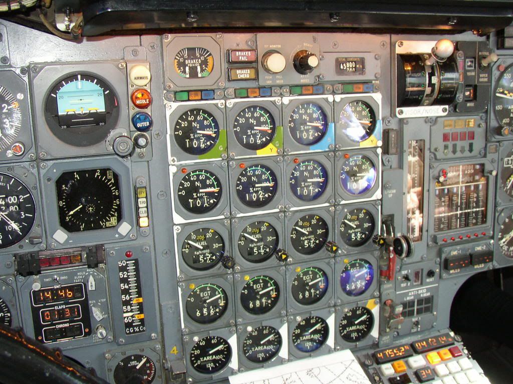
Only the lower digital counter was actually a display, and was a digital repeater of the total fuel flow information being displayed by the pointer on the dial. The upper digital counter was merely a digital indication of the value to which the internal yellow triangular bug had been set by the F/E using the bug setting knob on the lower right of the gauge.
Very briefly, during the pre-flight set up, the F/E would calculated the expected fuel flows for each engine, during the take-off whilst using re-heats. He would set this on the bug, and this achieved two things.
Firstly, it gave him a good visual indication whether the required fuel flows were being achieved. Too low a fuel flow would indicate a re-heat problem on that engine.
Secondly, it programmed the expected fuel flow into the engine take-off monitor, as this was one of the parameters that had to be satisfied in order for the monitor to illuminate the Green \x93Clear-to-Go\x94 light.
The Green \x93Clear-to-Go\x94 light was one of three \x93Power Management\x94 lights immediately above the N2 gauge for each engine, the other two being an Amber \x93Configuration\x94 light and a Blue \x93Reverse\x94 light. Some take-offs would require all four Green lights to be on, other take-offs, depending on ambient conditions, aircraft weight and runway length, might only require three Green lights.
...What was the peak consumption per engine, and why two digital displays on each gauge?...
The maximum peak consumption predicted was 21,700 kg/eng/hr, or 86,800 kg/hr total. This would have been predicted for a re-heated take-off, at +8\xb0C, at an elevation of -1,000 PA.
More typically, on a standard day, at a sea level airfield, 20,700 kg/eng/hr, or 82,800 kg/hr total. You can probably see why we turned the re-heats off fairly quickly!
...accelerating to Mach 2.0 and immediately slowing down again....we only went to 43,000 feet so the sky did not get very dark...
43,000 ft is actually a bit too low for Concorde to be at M2.0, as you may see from this graph of her Flight Envelope. She would have been limited to around 525 kts / M1.7 at that height, so I suspect you may have been a little higher than you remember, possibly somewhere around 53,000 ft.
Happy New Year
Bellerophon
...I have been a Concorde fan since I won a flight on it in 1980...
Lucky devil! I'm glad you enjoyed the flight.
...There appears to be two digital displays per gauge as well as an analogue display...
Only the lower digital counter was actually a display, and was a digital repeater of the total fuel flow information being displayed by the pointer on the dial. The upper digital counter was merely a digital indication of the value to which the internal yellow triangular bug had been set by the F/E using the bug setting knob on the lower right of the gauge.
Very briefly, during the pre-flight set up, the F/E would calculated the expected fuel flows for each engine, during the take-off whilst using re-heats. He would set this on the bug, and this achieved two things.
Firstly, it gave him a good visual indication whether the required fuel flows were being achieved. Too low a fuel flow would indicate a re-heat problem on that engine.
Secondly, it programmed the expected fuel flow into the engine take-off monitor, as this was one of the parameters that had to be satisfied in order for the monitor to illuminate the Green \x93Clear-to-Go\x94 light.
The Green \x93Clear-to-Go\x94 light was one of three \x93Power Management\x94 lights immediately above the N2 gauge for each engine, the other two being an Amber \x93Configuration\x94 light and a Blue \x93Reverse\x94 light. Some take-offs would require all four Green lights to be on, other take-offs, depending on ambient conditions, aircraft weight and runway length, might only require three Green lights.
...What was the peak consumption per engine, and why two digital displays on each gauge?...
The maximum peak consumption predicted was 21,700 kg/eng/hr, or 86,800 kg/hr total. This would have been predicted for a re-heated take-off, at +8\xb0C, at an elevation of -1,000 PA.
More typically, on a standard day, at a sea level airfield, 20,700 kg/eng/hr, or 82,800 kg/hr total. You can probably see why we turned the re-heats off fairly quickly!
...accelerating to Mach 2.0 and immediately slowing down again....we only went to 43,000 feet so the sky did not get very dark...
43,000 ft is actually a bit too low for Concorde to be at M2.0, as you may see from this graph of her Flight Envelope. She would have been limited to around 525 kts / M1.7 at that height, so I suspect you may have been a little higher than you remember, possibly somewhere around 53,000 ft.
Happy New Year
Bellerophon
29th Dec 2010, 11:28
permalink Post: 1039
Further PS ref. the fuel flow gauge - somone wondered if the target flow veeder counter was for reheat. We now know that it wasn't, but you will see a small 'Fe' annunciation in the 9 o' clock position indicating that the gauge is measuring engine flow only. When fuel is being supplied to the reheats this changed to 'Ft' with a white background to indicate that the gauge was displaying combined fuel flow. (Fe=engine, Ft=total)
15th Jan 2011, 10:59
permalink Post: 1100
A Journey Back In Time !!
OK, here is a photo that I took at Fairford in November 1976. I'd just had my very first Concorde flight on a brand new G-BOAD, and took this flight deck photo in the hangar later that afternoon (the doors are open hence the late afternoon Cotswold sky. The point of this rather poor (sorry guys, I was young for goodness sake) photo is to look at just how subtly different the 1976 flight deck WAS.
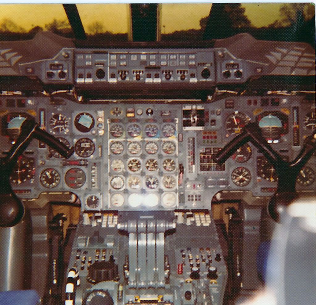
The first thing I know EXWOK and BELLEROPHON will (maybe) notice is that originally OAD had a 'normal colour' electroluminescent light plate on the visor indication panel. (If I remember rightly (it was a million years ago chaps) when this one 'stopped lighting' we could not get a replacement and had to rob 202 (G-BBDG) at Filton; this one being the same black development aircraft colour that OAD has to this day.
The OTHER first thing that you may notice is the Triple Temperature Indicator on the captains dash panel. (The first officer had his in in similar position). These got moved around (twice in the end) when TCAS was installed in the mid-90's. It was amazing just how much equipment got moved around over the years, in order to 'shoe-horn in' various bits of extra equimpent.
The cabin altimeter here fitted just above the #1 INS CDU also got moved (to the centre consul) when the FAA 'Branniff' modifications were embodied later in the 70's. It's spot got occupied by a standy altimeter mandated by the FAA but this was removed after Branniff ceased flying Concorde; the cabin altimeter returning to it's former home. The REALLY observant will notice that there is neither an Autoland Ca3/Cat2 identifier on the AFCS panel (glued on by BA at LHR) or the famous and precision built 'Reheat Capabilty Indicator' flip down plate fitted to the centre dash panel a few years later by BA.
Also not shown here, as they were buyer furnished equipment also fitted at on delivery LHR, are the two ADEUs (Automatic Data Entry Units, or INS Card readers). These were located immediatel aft of the CDU's and were used for bulk waypoint loading ('bulk' being 9, the most that the poor old Delco INU memory could handle). These were removed in the mid 90's when the Navigation Database was fitted to Concorde INUs, and bulk loading then was achieved by simply tapping in a 2 digit code. (Hardly the elegence of FMS, but still very elegent in comparison with the ADEU's, and worked superbly). A little note about these ADEU things; You inserted this rather large optically read paper data card into the thing and the motor would suck the unsuspecting card in. As often as not the ADEU would chew the card up and spit the remnants out, without reading any data, or not even bother spitting out the remnants at all. Removing these things FINALLY when the INUs were modified was absolute joy!!
ps. When G-BOAG (then G-BFKW) was delivered in 1980 it had neither any of the Branniff mods or ADEUs fitted. (Also the INS was not wired for DME updating). This meant that obviously she could not fly IAD-DFW with Branniff but also she could not do LHR-BAH either, because of the lack ADEUs. (You could not manually insert waypoints quick enough over the 'Med', or so the guys told me. So for the first few years good old FKW/OAG just used to plod between LHR and JFK. And plod she did, superbly. She never did get the ADEUs (not necessary thank goodness when the INUs got modified) but we wired in DME updating and so she could navigate around with the best of them.
My gosh I do prattle on, sorry guys.
Best regards
Dude
PS Welcome back Landlady, hope you've recovered from your fall XXXX
Last edited by M2dude; 15th Jan 2011 at 11:29 .
18th Jan 2011, 09:30
permalink Post: 1122
I so remember the BAe AST images from the 1980s, I always thought what a potentially nice looking aeroplane she was. I guess that vastly improving the L/D & T/W ratios could go quite a long way to improving the operating economics, but the noise issue was always going to be the crippler. (I know that they were looking at a 'leaky' version of the OLY593, ie. a very low bypass ratio, but this of course would still not really cut the mustard as far as noise goes). I guess there are no current takers then

Clive, you really surprise me when you say you don't think that composites would be used from a future SST, is there a material reason for this? (I'm curious because being of a simple avionic brain, I always assumed composites would be used. But if anyone knows this stuff, you certainly would Clive ).
).
To answer Mike-Bracknell's original query, as far as avionics goes we can really go to town. For her age Concorde had some truly amazing aircraft systems, for instance the flying controls. To enable mechanical control (both FBW channels failed) there was a highly complex and heavy mixing unit under the rear floor. (To mix pitch and roll pilot mechanical demands into differential elevon demand inputs). This of couse would have to be done away with, as well as the relay jacks and replaced with a pair of side-sticks. (See posts on previous page). A 2 crew operation would obviously be the way to go, but neither desirable or possible in my view when Concorde was designed. A triplex or quadruplex flying control system (possibly even integrating autoflight) would replace the Concorde collection of several analog boxes with a very small handful of lightweight digital units.. The powerplant control will have major weight savings, just take a look at this lot. 8 Engine Control Units, 4 Bucket Control Units, 2 Nozzle Angle Scheduling Units, 4 Reheat Amplifiers, 8 AICUs, 4 Air Intake Sensor Units and a single Air Intake Test Unit could potentially be replaced by just 4 multi-channel EEC type units. (On subsonic aircraft the EECs are mounted on the engine itself, not sure if that's a good idea for an SST, given the operating environment. Air Data and Navigation systems take a major simplification and weight saving, the 3 INUs and 2 ADCs (All of them straight from the 'rent a hernia' store as far as weight goes), could be replaced by a single ADIRU and a SAARU. The fuel indication/management side of things (2 FQI packs, 2 level switching packs and 3 CG computers) would probably be replaced by a single Fuel Processing unit. Ahhhh perchance to dream

Best regards
Dude
Clive, you really surprise me when you say you don't think that composites would be used from a future SST, is there a material reason for this? (I'm curious because being of a simple avionic brain, I always assumed composites would be used. But if anyone knows this stuff, you certainly would Clive
).
To answer Mike-Bracknell's original query, as far as avionics goes we can really go to town. For her age Concorde had some truly amazing aircraft systems, for instance the flying controls. To enable mechanical control (both FBW channels failed) there was a highly complex and heavy mixing unit under the rear floor. (To mix pitch and roll pilot mechanical demands into differential elevon demand inputs). This of couse would have to be done away with, as well as the relay jacks and replaced with a pair of side-sticks. (See posts on previous page). A 2 crew operation would obviously be the way to go, but neither desirable or possible in my view when Concorde was designed.
A triplex or quadruplex flying control system (possibly even integrating autoflight) would replace the Concorde collection of several analog boxes with a very small handful of lightweight digital units.. The powerplant control will have major weight savings, just take a look at this lot. 8 Engine Control Units, 4 Bucket Control Units, 2 Nozzle Angle Scheduling Units, 4 Reheat Amplifiers, 8 AICUs, 4 Air Intake Sensor Units and a single Air Intake Test Unit could potentially be replaced by just 4 multi-channel EEC type units. (On subsonic aircraft the EECs are mounted on the engine itself, not sure if that's a good idea for an SST, given the operating environment. Air Data and Navigation systems take a major simplification and weight saving, the 3 INUs and 2 ADCs (All of them straight from the 'rent a hernia' store as far as weight goes), could be replaced by a single ADIRU and a SAARU. The fuel indication/management side of things (2 FQI packs, 2 level switching packs and 3 CG computers) would probably be replaced by a single Fuel Processing unit. Ahhhh perchance to dream
Best regards
Dude
3rd Apr 2011, 21:16
permalink Post: 1252
Bellerophon
I remember that -- the initial rotation was pretty normal other than being a bit faster, then from there it was brought up to a very steep climb (it feels worse than it is, but I was guessing it was around 22 or so degrees -- it has to do with eyeballing the angle of the horizon to the plane's current path -- 22.5 degrees is 1/4 the way up, 30 is 1/3, 45 is 1/2, 60 is 2/3's and so forth). Clearly I'm not a human ADI

Quote:
|
You call 3-2-1 Now, start your stopwatch, pre-set to countdown from 58 seconds, and slam the throttles fully forward till they hit the stops. Four RR Olympus engines start to spool up to full power and four reheats kick in, together producing 156,000 lbs of thrust, but at a total fuel flow of 27,000 US gallons per hour. A touch of left rudder initially to keep straight, as the #4 engine limiter is limiting the engine to 88% until 60 kts when it will release it to full power. The F/O calls
Airspeed building, 100 kts, V1
, and then, at 195 kts,
Rotate
. You smoothly rotate the aircraft, lift-off occurs at around 10\xb0 and 215 kts. You hear a call of
V2
but you keep rotating to 13.5\xb0 and then hold that attitude, letting the aircraft accelerate.
The F/O calls Positive Climb and you call for the Gear Up . On passing 20 feet radio height, and having checked the aircraft attitude, airspeed and rate of climb are all satisfactory, the F/O calls Turn and you slowly and smoothly roll on 25\xb0 left bank to commence the turn out over Jamaica bay. Some knowledgeable passengers will have requested window seats on the left side of the aircraft at check-in, and are now being rewarded with a very close look at the waters of Jamaica Bay going by very fast! As you accelerate through 240 kts, the F/O calls 240 and you pitch up to 19\xb0 to maintain 250 kts and keep the left turn going to pass East of CRI. |
5th Apr 2011, 18:32
permalink Post: 1259
Quote:
| During the take off roll there was a power check called (by the FE, I think). I've heard this on recordings and videos variously as "power checked" and "Power set". Assuming they are one and the same check, which is correct |
I think you are referring to the 100kt call, when the F/E was expected to give a call as to the state of the powerplant [both engine and reheat] achieving desired power for take off. He was assisted in this decision by the illumination of 4 green lights [ one per engine] which came on if the engine power was OK. Should one green light fail then he would confirm the correct engine operation by observing that engine's N2 and Area position
If all OK at 100kts the F/E would call ---- "Power Set"
If not all Ok then he would call ----------" Engine Failure" which would
result in a rejected Take off
In the early days there was no concession and every take off had to have 4 green lights illuminated so the call then was " 4 Greens" , but when the concession came along that term would not fit so the change in call
The concession were
1] one green light out [seeabove]
2] and basically if weight, and airport conditions allowed it a take off could be continued even with one reheat failed at 100kts
Up to 60 kts the F/E could reselectt a failed reheat so hoping it would be
OK by 100kts
At 100kts the conditions in the above concessions applied
Above 100kts the take off would continue even if a reheat failed however
if another fails when below V1 the take off would be rejected
So finally to answer your question the correct call [well in 1998] was
" Power Set "
5th Apr 2011, 20:54
permalink Post: 1262
Thanks Brit 312. "Power set" it is, then. I was aware of the '3 reheat' possibility which is decided before T/O depending on T/O parameters ('is this a 3 re-heat day or a 4 re-heat day?').
On the P1 side of the cockpit is a small hinged piece of metal which can be moved to show '3' or '4'. This is set before flight depending on whether 3 or 4 re-heats are the acceptable minimum for take off that day, so if there is a re-heat failure on T/O, a glance at that indicator will show if it's OK to continue with '3 lit' or not.
On the P1 side of the cockpit is a small hinged piece of metal which can be moved to show '3' or '4'. This is set before flight depending on whether 3 or 4 re-heats are the acceptable minimum for take off that day, so if there is a re-heat failure on T/O, a glance at that indicator will show if it's OK to continue with '3 lit' or not.
6th Apr 2011, 06:17
permalink Post: 1263
Ahhhh... the famous Reheat Capability Indicator. (Yes that was its official title). I seem to remember that before we did the modification to fit the 'RCI' in the late 1970s, the guys used to set an INS CDU thumbwheel as a memo to whether the take-off was a 'go-er' or a 'stopper'.
It seems a million years ago when we fitted this high presicion lump of alluminium. (Hang on a minute, it WAS ).
).
Best regards
Dude
It seems a million years ago when we fitted this high presicion lump of alluminium. (Hang on a minute, it WAS
).
Best regards
Dude
7th Apr 2011, 18:44
permalink Post: 1272
Power limit to 60kt
I believe that engine #4 was limited to somewhat less than max power until 60kt because of a vibration issue. Did this mean that reheat for that engine could not be selected until 60kt was achieved?
7th Apr 2011, 20:14
permalink Post: 1273
All 4 reheats were selected 'on' before take off. They wouldn't actually light until the engine was up to a certain power, so the answer is 'no'. The power-limiting ensures no. 4's re-heat doesn't light below 60kts.
Watch a video of Concorde taking off which gives the view from behind. You'll notice no.4 light up marginally after the other 3 (but there's not much in it as it didn't take the aeroplane long to get to 60kts!).
Watch a video of Concorde taking off which gives the view from behind. You'll notice no.4 light up marginally after the other 3 (but there's not much in it as it didn't take the aeroplane long to get to 60kts!).
7th Apr 2011, 20:56
permalink Post: 1274
Not quite right: the reheats ignite if
(At temperatures colder than -35\xb0C the engine control schedule limits the N1 of all engines to 88% or less.)
Regards
- throttle lever >10% open; at takeoff the throttle levers have to be slammed to fully open within a second
- selected RHT or CTY
- N1 >81%
(At temperatures colder than -35\xb0C the engine control schedule limits the N1 of all engines to 88% or less.)
Quote:
|
Originally Posted by
Brit312
Up to 60 kts the F/E could reselect a failed reheat so hoping it would be OK by 100kts
|
Last edited by Quax .95; 11th Apr 2011 at 16:34 . Reason: T/O-case added
7th Apr 2011, 21:24
permalink Post: 1275
Thaks Quax. So all 4 reheats should light about the same time, then, regardless of power limiting on #4? It does seem that #4 lags a fraction in vids I've seen.
8th Apr 2011, 15:25
permalink Post: 1283
Take off reheat selection
I seem to recall from my two take offs in 1978 or 9 that all four reheats were selected in pairs for take off and lit while holding on the brakes, with a preamble/warning over the PA that this was what was going to occur. Is this another indication of my failing "little grey cells" or did the procedure change?
Same PA announcement and lighting in pairs also occurred when going supersonic.
Same PA announcement and lighting in pairs also occurred when going supersonic.
8th Apr 2011, 16:29
permalink Post: 1284
For take-off reheat was selected (armed) on all 4 engines together, and certainly not in pairs. (As was stated previously, once 81% N1 was reached the reheat light-up sequence was automatically initiated). You would not wind up on the brakes either, the carbon brakes were extremely sensitive to overtorquing. For transonic acceleration however you are quite right about the 'burners in pairs' bit.
Last edited by Jetdriver; 10th Apr 2011 at 09:23 .