2nd Sep 2010, 19:44
permalink Post: 191
Hydraulic failures
I had the pleasure of one trip as SLF on Concorde LHR - JFK (1978/9? grey cells depleting) which involved a return to LHR after dumping fuel due to hydraulic failure of two systems. No complaints from me, two take offs and landings for the price of one plus two hours of additional catering at LHR while the aircraft was fixed. Big run on asprins by the time we approached JFK!
However on the second departure the AC also suffered loss of hydraulic systems and I understood that it arrived at JFK on one system. After a storm delay at JFK I departed on AA listening to the ATC on the IFE with the Concorde following. Yet again the Concorde requested fuel dump and return due to hydraulic failures. The previous days I believe the Concorde had also experienced hydraulic failures and at one point BA cancelled some flights. AF were not experiencing the same problems and I read several years later that the problem was attributed to minute quantities of water being introduced into the system by a repenishing tanker being parked outside, wheras AF stored their tanker inside. The water then generated steam when the system ran with consequent seal failures.
Is the above cause correct, or was there more to the story?
Apart from all the normal Concorde observations, I also noticed that when trolling around over Bristol dumping fuel at a relatively high AoA the rear outboard surfaces, I was seated at the rear, vibrated at an alarming aplititude and frequency. Would this be caused by aerodynamic buffet or rapid auto pilot control inputs?
Thanks in anticipation.
20th Sep 2010, 16:18
permalink Post: 424
Interesting & nostalgic thread. Nice to see this monumental aviation achievement still generates such passion...
In case it's of interest (and suitable health warning as the memory fades)...
The heat did evaporate water vapour in the airframe - reducing corrosion. I remember when the 5 BA aircraft were returned to service, after the post-accident mods, their weight and balance certificates were prepared and found to be out by (IIRC) more than a tonne. This represented water in the airframe present after a year on the ground, and was gone again after a couple hours of supercruise on return to service. Back to the weighbridge for new W&B Certificates....
Vortex lift caused buffet which felt very similar to a conventional wing's stall/low speed buffet. At landing weights (I hate the trend of using the term "mass": weight is a force, mass is not!) you felt the buffet start as you reduced speed (CAS: Vc) to about 250kts. It was handy as a reminder that you should select visor down / nose to five below 250kts (the recommendation was as you slowed through 270kts, but latterly we were in the habit of holding at 250kts nose/visor up - I think TCAS was quoted as a backup to the more limited visibility in that config). At takeoff weights, the buffet went at more like 270kts accelerating. So I'm pretty sure there was no vortex lift at AoA > 7 degrees (250kts at LW).
Recommended subsonic cruise at MTOW was F260 / M0.95 which was equal to Vmo of 400kts (CAS). It was best cruise because Vc=400kts was also min drag at MTOW. F280 meant a slightly more draggy speed of 384kts, but some preferred it because when cleared to climb & accelerate supersonic (the official expression was "go for it") it gave you a bit of slack against Vmo when eng put the reheats in. But we tended to ignore the overspeed warning anyway: it was supposed to go really really fast...
We never flew with visor down and nose up unless it was bust - that config was only used during pushback (except one captain who always thought it looked better visor up....). Visor down max Vc was 325kts/M0.8 so it would limit subsonic cruise, and besides it made a racket like that.
It was a beaut in x-winds - a total lack of yaw-roll couple meant you just straightened the 'plane up with rudder and carried on into the flare as normal. No roll to counteract, and the sideways "lift" created by the rudder deflection on the fin pretty much equalled the x-wind drift. Nice.
Wind limits were Crosswind 30kts (15kts contaminated or autoland), Headwind for autoland 25kts (or manual "reduced noise" approach: that's a technical way we used to reduce the noise footprint down to 800' by flying at 190kts then reducing to a target speed of Vref+7kts at that point). Tailwind 10kts. All these limits were, of course, subject to "on the day" performance limits calculated at the time. I seem to remember there was an over-arching limit of 6000' on r/w length, subject again to "on the day" performance limits. OK, I cheated on this paragraph and dug out FM Vol 2a.
There were loads of other limitations which were, by and large, more "esoteric" than a conventional airliner and which had to be learned for the conversion course. It really made the head hurt, and would have been impossible without a big loverrly picture of the beast on the wall chucking out yellow smoke and making noise. Even a static picture of her seemed to make noise...
No one who flew it could really believe their luck, but one thing for sure is "they don't build them like that any more"...
Ahhhhhhhhhhhhhh..........
20th Sep 2010, 23:19
permalink Post: 433
Hi
I know that there were stall problems with the Trident due to the main wing blocking the air flow to the elevators. I just wondered if there was any side slip problems etc due to the air flow being blocked to the vertical tail by the big delta wing especially at large AoA on landing? If so what was the undoubtably clever solution? Mind you I may be seeing problems where there are none!
Regards
Nick
20th Sep 2010, 23:48
permalink Post: 434
Nick - good question. The elevons were not hidden at high AoA (no elevators, no T-tail issue) but high alpha longitudinal stability was an issue in early development, one of the fixes were the moustache strakes you see at the front - they help energise the wing vorteces and improve rudder authority at high AoA. Apparently. Well that's what they told us at ground school - the result was that right up to limiting AoA all flight controls were effective, including the potentially blanked-off rudder. IIRC the stick-shake was at about 16 degrees which left about 3 degrees slack above approach AoA and it all worked just fine in that environment.
21st Sep 2010, 15:39
permalink Post: 442
Quote:
|
Originally Posted by
Nick Thomas

I just wondered if there was any side slip problems etc due to the air flow being blocked to the vertical tail by the big delta wing especially at large AoA on landing? If so what was the undoubtably clever solution?
|
Your questions were already partly answered by NW1.
The solution was indeed in those two narrow strakes on the nose that generated a vortex on either side, the higher the AoA, the stronger.
Those two vortices "folded upwards", well before the leading edge of the wing, and around to the top of the fuselage, where they "stuck down" the air flow right to the end.
Hence the vertical tail was not "blanketed" by disturbed/turbulent air from the fuselage, and remained effective even at quite high angles of attack.
It was certainly a clever solution... but not new.
As stilton said, it was already used on the MD80.
On Concorde they had already been tested in the windtunnel and found to be effective, so if you look at photos of prototype 001 on its very first flight you will see they're already in place.
Vortices are funny things... usually you don't see them, but they contain quite a lot of energy and persist for quite a long time before dissipating. That's why those two small planks on Concorde work so well.
CJ
21st Dec 2010, 18:09
permalink Post: 929
quote
 uring landing, Concorde isn't flared at all, it is flown onto the ground at a constant pitch attitude.
What does happen is that the ground effect over the last 50 ft or so of height considerably flattens the trajectory, so you do not touch down with the same vertical speed as during the final approach !
What also happens is that the ground effect produces a pitch-up moment, so the pilot has to push forward on the stick to maintain the same pitch attitude.
Putting the nosewheel down after touchdown is enough to completely \x93ruin\x94 the lift, so that there is no need for \x93lift-dumpers\x94 or spoilers.unquote
Sorry Christan, but I did the original pre first flight work on this one, so I know you are mistaken here. You are abolutely correct in saying that the ground effect cushions the aircraft beautifully so that all the pilot needs to do is to hold constant attitude, but the ground effect also produces a nose DOWN moment, so the pilot must exert a steadily increasing pull on the stick to maintain the correct attitude.
So far as lift on the ground is concerned, the aircraft attitude (and therefore the AoA) is substantially zero. without any flaps then the lift is also zero so, as you say, leif dumpers would be useless. They could of course act as airbrakes but you wouldn't add their weight and complexity just for that.
I see I have covered about 10 pages out of the 45 or so, but I don't want to hog this thread so I had better shut up for a while
CliveL
uring landing, Concorde isn't flared at all, it is flown onto the ground at a constant pitch attitude.
What does happen is that the ground effect over the last 50 ft or so of height considerably flattens the trajectory, so you do not touch down with the same vertical speed as during the final approach !
What also happens is that the ground effect produces a pitch-up moment, so the pilot has to push forward on the stick to maintain the same pitch attitude.
Putting the nosewheel down after touchdown is enough to completely \x93ruin\x94 the lift, so that there is no need for \x93lift-dumpers\x94 or spoilers.unquote
Sorry Christan, but I did the original pre first flight work on this one, so I know you are mistaken here. You are abolutely correct in saying that the ground effect cushions the aircraft beautifully so that all the pilot needs to do is to hold constant attitude, but the ground effect also produces a nose DOWN moment, so the pilot must exert a steadily increasing pull on the stick to maintain the correct attitude.
So far as lift on the ground is concerned, the aircraft attitude (and therefore the AoA) is substantially zero. without any flaps then the lift is also zero so, as you say, leif dumpers would be useless. They could of course act as airbrakes but you wouldn't add their weight and complexity just for that.
I see I have covered about 10 pages out of the 45 or so, but I don't want to hog this thread so I had better shut up for a while
CliveL
22nd Dec 2010, 16:22
permalink Post: 944
Thanks for yours reply.

BTW, what about the super-stabilization? Does it only function when the
aircraft was lift on for 10 minute or for a whole flight regime? Also, what is
the stalling AoA of the Concorde?
Finally, What does the function of the Thrust recuperator and how does it work?
Edit: According to the CliveL picture, why Concorde wing LE has to droop down?
Is it use to produce the "negative drag" by the vortex?
Also, does the tip of the wing always has a negative AoA at all flight regime
or does it gonna bend up as the airspeed increase?
Thanks for all of yours reply.
Best regards
Last edited by Mr.Vortex; 22nd Dec 2010 at 16:31 . Reason: add something
22nd Dec 2010, 20:13
permalink Post: 950
Quote:
|
Originally Posted by
exwok
Hazy recollection - effectively an additional autostabilisation input in the nosedown sense active at high alpha/low EAS.
Ultimately applied a further nose down elevon input (4 degrees????) if EAS was less than (140kts???? That's a VERY low speed). (Colloquially known as 'super-duper stab' on my course) |
To cover this case the 'superautostabiliser'was developed. It effectively restricts the rate of variation of incidence so that, if the pilot entered into an avoidance manoeuvre of sufficient magnitude to trigger the stick wobbler, i.e. about 1.5g, he would be able to recover easily without exceeding the maximum incidence demonstrated in flight (which was in fact slightly greater than the maximum steady incidence limit). This superautostab had gain scheduled against AoA and also included phase advanced pitch rate and speed terms. Finally, there was a 'yaw superautostabiliser which applied rudder as a function of lateral acceleration to restrict sideslip which (see below) could affect the maximum lift attainable. [Note that because of the dynamics of slender aircraft operating at high AoA it was readily possible to develop sideslip in a turn]
Hope that is clear.
Whilst talking about maximum lift etc. can I confirm the numbers quoted in an earlier posting for the start of vortex lift - about 6 or 7 deg AoA at low speed, and for the AoA at maximum lift - about 23 deg. This is where the pitching momemt curve vs AoA 'breaks'. It is not a stall in the conventional sense because of course the flow over the leading edge has been separated long ago. Instead it is the AoA at which the LE vortices become 'too big for their boots' and go unstable and 'burst'. This AoA is sensitive to sideslip and the leading wing half will go first.
CliveL
24th Dec 2010, 13:02
permalink Post: 988
 Christian asked if there was an aerodynamicist in the house - I guess that would be me!
The original question was whether there was any vortex activity in subsonic cruise, but the discussion went on to ask about designing for subsonic drag I think.
The answer to the first bit is that the vortex flow started in a gentle manner from about 6 or 7 deg AoA and got steadily stronger. Depending on the chosen cruise speed and the aircraft weight, the subsonic cruise AoA would have been in the region of 4.5 to 5 degrees, i.e. below any significant vortex development. 6/7 deg would correspond to something in the range 250 to 280 kts probably (I haven't done the sums)
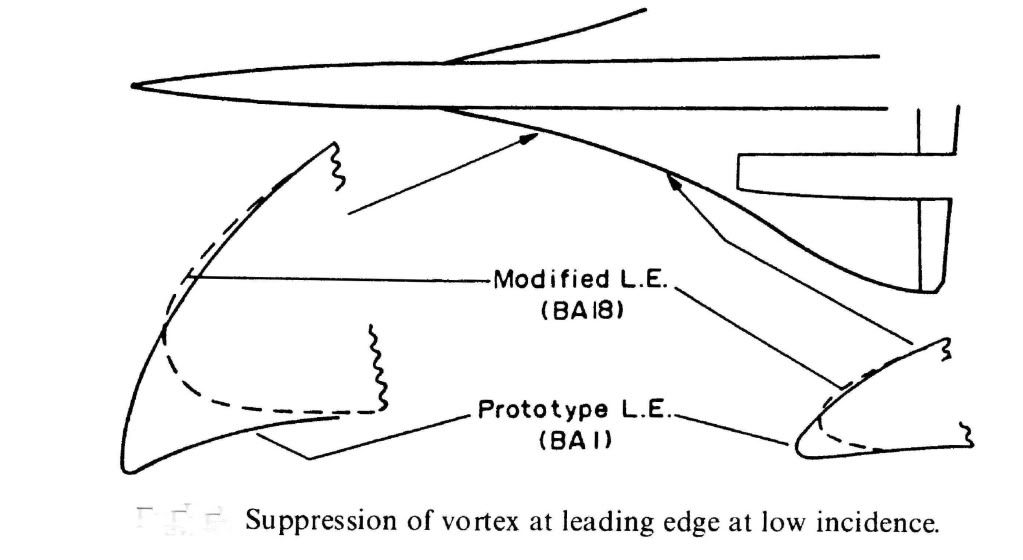
What we were trying to do for subsonic cruise was to have what is known in the trade as 'leading edge suction' acting on a nice bit of forward facing area so that it tried to drag the aircraft forwards as it were. As you can see from the diagram the prototype aircraft had a much more cambered LE so that both suction and forward facing area were very reasonable. This prototype shape was nicely rounded so that LE separation and top surface vortex generation started at a higher AoA than on the production aircraft. Unfortunately this shape, which featured a rather sharp LE on the undersurface, generated a vortex on the undersurface of the wing in supersonic flight and low AoA (near zero 'g'). This vortex got into the intake and caused the engine to surge, so we had to redesign the LE ahead of the intakes as shown. This cost us a little subsonic drag, so you can see from the diagram what you need to do to keep subsonic cruise drag down.
Hope this answers the questions
CliveL
24th Dec 2010, 16:15
permalink Post: 991
Thanks again for a great pics and great explanation.
I'm was wondering that, according to the manual and some document said
that the vortex lift start to form on wing tip first. Why's that happened?
Why not the root of the wing first?
Is it cause by the local wing tip vortex push the air causing more upwash
and hence more effective AoA causing it to reach the stall AoA first is that right?
Also, does the wing vortex on the Concorde has an influence or the effect on
the rudder?
Thanks for your reply.
Best regards
24th Dec 2010, 17:56
permalink Post: 997
[xxxxquote=Mike Bracknell]
Trust me, i'm definitely just here for the ride (so to speak) and quickly defer to you and the others who definitely know! Mike Bracknell[xxxx/quote]
Hell Mike, I meant I should leave it for others who definitely know, not you!
[xxxxquote]A little p.s. from me - having looked at Clive's diagram on this page showing the bathtubs, aren't the strengtheners the oval cups outboard of the main fixings on the page? with one pointed to by the words "Bottom machined skin panel"?
This looks like it's another layer of shear in order to fulfil the brief of working around the reported skin problems in that area. Just strange it had to break the surface like that? [xxxx/quote]
I don't think so Mike, there are far too many of them. It looks more like 'pocketing' of the machined skin to reduce weight; and incidentally that SA overdid it, since there were clearly cracks developing along the spanwise joints between the various wing sections.
Incidentally, doesn't that picture show ever so clearly why designing and fitting that postGonesse Kevlar liner to the lower skins was such a difficult job!
[xxxxquote=ChristiaanJ]If so, they are indeed shown in the structural repair manual and listed as 'doublers'. There are ten of those, from spar 62 to spar 71.
Reading "between the lines", the modification dates from about 1978, and was applied by successive service bulletins to both the BA and AF aircraft. [xxxx/quote]
Yes, I agree, they look like skin doublers put on as a repair job, and that makes (to me) a lot more sense than additions to increase outer wing stiffness. What has confused me from the beginning was that I equated "outer wing stiffness" with "outer wing torsional stiffness" because I could see why somebody might want to increase that but I couldn't, and can't, see why anyone would want to increase outer wing bending stiffness - if you get a little more dihedral who cares? But additional material to increase or recover fatigue life is another matter altogether.
Why external? Just look at that drawing - where could you add additional bending material easily?
[xxxxquote=Landroger]Digital control is a hell of a lot easier than Analogue - in my humble opinion.[xxxx/quote]
Depends when you were born Roger. Now if you came into this world before WW2 ......
[xxxxquote=Mr Vortex]I'm was wondering that, according to the manual and some document said that the vortex lift start to form on wing tip first. Why's that happened? Why not the root of the wing first?
Is it cause by the local wing tip vortex push the air causing more upwash
and hence more effective AoA causing it to reach the stall AoA first is that right?
Also, does the wing vortex on the Concorde has an influence or the effect on
the rudder? [xxxx/quote]
Ah! this gets a little complicated. Every lifting wing generates a pair of vortices at the tip, but these are not the vortices most people associate with Concorde. The massive vortices you see when the air is moist and the water vapour condenses out because of the drop in air pressure inside the vortex start, as you suggest at the wing root from that highly swept leading edge. The wingtip vortices are still there, even when the main vortices are doing their stuff, so Concorde actually has two sets of vortices acting on the upper surface, although this is not obvious to the casual observer.
Simply, the wing vortex has no effect on the rudder.
But whilst I am writing about vortices, can I digress to talk about the 'moustaches' aka GT6. Somebody, I forget who, asked about their use for controlling longitudinal stability and somebody else replied, quite correctly, that they were a contribution to lateral stability. What was happening without them was that high AoA (by which I mean in excess of about 10~12 degrees) the 'crossflow' on the front fuselage generated a pair of small vortices which, in sideslip, wandered across the base of the fin. This gave some sidewash that cancelled the 'incidence' coming from the sideslip itself so that the bottom of the fin was effectively operating at zero slip and therefore zero lift. Result - the weathercock stability dropped to virtually zero for small sideslip angles. The small vortex generators (Generator Turbillon or GT) had the effect of fixing the location of the origin of the forebody vortices so that they didn't wander - in fact they tended to become entrained into the main wing vortices - problem solved.
Now if I can sort it out I will try to upload some pretty pictures showing those two sets of wing vortices.
CliveL
24th Dec 2010, 20:04
permalink Post: 1000
What an amazing pictures!!. Thanks CliveL
So does the nose stake of the aircraft that sit below the Capt/FO sliding window
is what you're refer to the GT6 things right?
And if possible, I would like to know why the vortex start to form on the wing tip
[The outer wing part] first and the moving toward the wing root [inner wing
part] as the AoA increase.
Thanks again
Best regards
So does the nose stake of the aircraft that sit below the Capt/FO sliding window
is what you're refer to the GT6 things right?
And if possible,
I would like to know why the vortex start to form on the wing tip
[The outer wing part] first and the moving toward the wing root [inner wing
part] as the AoA increase.
Thanks again
Best regards
26th Dec 2010, 09:38
permalink Post: 1009
OK Vortex Lift for Dummies!
Lets start with a comparison of the lft on a conventional subsonic wing with that of a slender wing like Concorde:
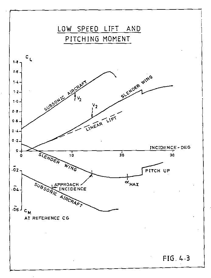
The subsonic line is linear, the slope depends on the geometry of the wing; high aspect ratio wings have a higher slope than low aspect ratio, unswept wings a higher slope than swept. Concorde, being a low aspect ratio swept wing has no chance!
To get a decent approach speed with a delta wing which has 'conventional' wing sections you need either a long U/C and work with high landing AoA or a large wing area to get the wing loading down. I would put the Avro Vulcan in the latter class. A large wing area is bad news for supersonic aircraft, but the Germans, working during WW2 found that if you give the delta sharp leading edges the flow separates at the leading edge and forms a pair of vortices that flow over the upper wing surface.
A vortex, if you could see it, is like a tornado (twister) turned on its side. The essential feature is that it is associated with low static pressures. As you get closer to the centre of the vortex the pressure drops more and more. The red zones at the centre of that transverse view are very low pressure indeed, but even the outer zones have quite low pressure.
I will have to put it up as a separate posting, but there are pictures that show that as AoA increases not only does the vortex get stronger (more suction) but the area of the wing affected by the vortex also inceases. This 'double whammy' gives the vortex a nonlinear effect. This 'nonlinear' lift is what is sometimes called 'vortex lift'.
It doesn't come for nothing - since by definition the flow is separated from the leading edge there is no alleviating 'leading edge suction' to reduce drag, and you won't go very far wrong if you take the drag of an aircraft with such a wing as Profile Drag plus Lift (times) tan AoA.
Concorde is a bit more subtle - the nose of the wing is drooped so that the flow does not separate until the AoA reaches 6 or 7 deg, giving us a good L/D in subsonic cruise whilst still having a healthy lift at approach speed.
Does this fit the bill?
CliveL
Lets start with a comparison of the lft on a conventional subsonic wing with that of a slender wing like Concorde:
The subsonic line is linear, the slope depends on the geometry of the wing; high aspect ratio wings have a higher slope than low aspect ratio, unswept wings a higher slope than swept. Concorde, being a low aspect ratio swept wing has no chance!
To get a decent approach speed with a delta wing which has 'conventional' wing sections you need either a long U/C and work with high landing AoA or a large wing area to get the wing loading down. I would put the Avro Vulcan in the latter class. A large wing area is bad news for supersonic aircraft, but the Germans, working during WW2 found that if you give the delta sharp leading edges the flow separates at the leading edge and forms a pair of vortices that flow over the upper wing surface.
A vortex, if you could see it, is like a tornado (twister) turned on its side. The essential feature is that it is associated with low static pressures. As you get closer to the centre of the vortex the pressure drops more and more. The red zones at the centre of that transverse view are very low pressure indeed, but even the outer zones have quite low pressure.
I will have to put it up as a separate posting, but there are pictures that show that as AoA increases not only does the vortex get stronger (more suction) but the area of the wing affected by the vortex also inceases. This 'double whammy' gives the vortex a nonlinear effect. This 'nonlinear' lift is what is sometimes called 'vortex lift'.
It doesn't come for nothing - since by definition the flow is separated from the leading edge there is no alleviating 'leading edge suction' to reduce drag, and you won't go very far wrong if you take the drag of an aircraft with such a wing as Profile Drag plus Lift (times) tan AoA.
Concorde is a bit more subtle - the nose of the wing is drooped so that the flow does not separate until the AoA reaches 6 or 7 deg, giving us a good L/D in subsonic cruise whilst still having a healthy lift at approach speed.
Does this fit the bill?
CliveL
26th Dec 2010, 09:51
permalink Post: 1010
 Ok, second picture (can anyone tell me how to attach more than one?)
These need a bit of explaining I'm afraid. They are 'oil flow' pictures - you paint the model wing with a mixture of paraffin, engine oil and lamp black and blow air over it. The resulting pattern shows how the air is flowing (or not flowing, which is its primary purpose) over the wing surface.
I the diagram marked up in red the 'S' shaped line is a typical streamline where the air is brought down onto the surface inboard, moves downstream and across towards the tip under the combined action of fore and aft velocity and vortex rotational velocity and tis finally lifted off the surface by the vortex. the triangular zone marked out in red is the area of the wing 'scrubbed' by the vortex flow. If you compare the pictures at various AoA you will see that this area increases substantially as AoA increases.
On the21 deg picture you can also see signs of a second vortex between the main vortex and the wingtip, but this is not the classic 'tip vortex'
CliveL
26th Dec 2010, 16:03
permalink Post: 1017
Vortex Lift.
Quote:
|
Does this fit the bill?
CliveL |
As the AoA increases when Concorde slows down, the vortex comes into being and becomes stronger as the angle increases, creating a low pressure tube into which the wing is 'sucked upwards' - vis vortex lift. How did I do?

Quote:
| These need a bit of explaining I'm afraid. They are 'oil flow' pictures - you paint the model wing with a mixture of paraffin, engine oil and lamp black and blow air over it. The resulting pattern shows how the air is flowing (or not flowing, which is its primary purpose) over the wing surface. |

Thanks for the explanation - it was less painful than I had feared.
Roger.
27th Dec 2010, 14:04
permalink Post: 1026
A pot pourri of responses after my Christmas reading!
This actually is interesting in that the n umbers show one of the fundamental features that made the Ol 593 such a good choice. If you look closely at the TO and cruise values you will find that at TO the overall compressor pressure ratio is 13.5 the compressor exit temperature 460 degC and the turbine inlet temperaure is 1152 degC. In cruise the pressure ratio is 10.5, the compressor exit is 565 degC and the TET 1100 degC.
Somebody, I can't find the exact post, was asking whether the elevated cruise total temperatures affected engine life, and here we see why this is so. As Christian said in another posting, when you compress air it gets hotter - from 21 degC to 460 degC at take off and from 127 degC to 565 degC in cruise. A fundamental limit on engine operation is the turbine entry temperature. Not only does it affect the maximum TO thrust you can get but also the continued exposure to cruise TETs has a very big effect on engine fatigue life, and engine manufacturers have shown extremes of ingenuity when developing new materials and ways of cooling the blades to increase allowable TET.
The problem with supersonic operations is that you start from an elevated intake delivery temperature so that when the flow exits the compressor it is already very hot 565 instead of 460 to be exact. But the maximum temperature one can stand for fatigue reasons is limited, therefore the amount of fuel you can pour in must be limited also, and the thrust you can develop per pound of airflow is roughly proportional to the fuel input/temperature rise. To get any sensible cruise thrust then one must squeeze the cruise TET as high as you dare for fatigue reasons but also you need to keep the compression ratio down so that the temperature going into the combustion chambers is as low as you can get away with. This tend to drive engines designed for extended supersonic operations to having a low pressure ratio. This is against the trend in subsonic operations where compression ratios have been steadily increasing along with bypass ratios.
The net result then is that the engine must be designed with a low OPR and must operate with cruise TET much closer to its TO TET value than would be necessary, or indeed desirable, on a subsonic design.
Actually, here, as on some other apparent carry-overs, one should look at the equipment supplier rather than the aircraft manufacturer to trace continuity. Here we have Messier supplying Concorde's gear and Dowty (OK they are now part of Messier) supplying the A330. And having worked on both, I seem to remember that the means of doing the shortening are quite different.
Yes, they both came out of the Bristol drawing office. One minor anecdote: the 'ramshorn' stick was a novelty to the Concorde flight test crews but they got to like it, or at least put up with it. All went well until it came to the time when Dave Davies, the ARB Chief Test Pilot, came to put his rubber stamp on the aircraft.
Concorde's seats, just like those on your car, could be moved back and fore to get your legs on the pedals and up and down so you could see over the bonnet (sorry, instrument panel). The control column of course stayed in one place, so the relationship of the 'horns' to ones thighs varied with ones height. Andre Turcat was about 6ft 2in, Trubbie and the others of average height. The smallest regular pilot was Jean Franchi at, I suppose, about 5ft 7 or 5ft 8. No problems. But Dave Davies was short like me and he found that he could not get full back stick and full aileron because the ramshorn fouled his thighs.
Consternation! Completely unacceptable! I don't know what arguments they used to convince him it was all OK really, but it got through certification. I would certainly be interested to learn from the pilots in this group as to whether it was ever a problem.
I can't resist this one!. Has anyone ever noticed/wondered about the tiny bit of the outer elevon that has been chopped off? That was my first real input into the design as a young erk looking at variability of touchdown conditions and coming to the conclusion that if the pilot got into trouble and was trying to pick up a trailing wing with too much AoA as well then he was likely to hit the ground with the downgoing elevon. I persuaded my boss that this was so and we made a small adjustment.
In self defence I am going to plead that this was well before the days of the Type 28 nozzle, so the issue of buckets contacting the ground first never came up!
To the point where an American Airline maintainance engineer, watching a prototype taking off and with full benefit of being located strategically for maximum sideline noise, remarked on what he described as 'visible acoustic radiation'
On another occasion, it was reputed that Stanley Hooker, watching a TO in the company of HRH the Duke of Edinburgh, remarked that "You know Sir that that noise represents less energy than it takes to boil an egg". to which he got the reply "Then I must congratulate you Sir Stanley, on producing so much noise for the expenditure of so little energy".
There was an effect and in consequence the aircraft performance brochures were formally calculated for north/south flight. Pity really, it would sometimes have been nice to be able to fly guarantee performance demonstrations in the most favourable direction
That's enough for today!
CliveL
Quote:
|
Originally Posted by
M2Dude
I hope this one is interesting; it's a Rolls Royce diagram illustrating what the wildly varying differences were in terms of the engine between take off and supersonic cruise. The primary nozzle can be seen at the rear of the engine, together with the reheat assembly and the secondary nozzle (reverser buckets).
|
This actually is interesting in that the n umbers show one of the fundamental features that made the Ol 593 such a good choice. If you look closely at the TO and cruise values you will find that at TO the overall compressor pressure ratio is 13.5 the compressor exit temperature 460 degC and the turbine inlet temperaure is 1152 degC. In cruise the pressure ratio is 10.5, the compressor exit is 565 degC and the TET 1100 degC.
Somebody, I can't find the exact post, was asking whether the elevated cruise total temperatures affected engine life, and here we see why this is so. As Christian said in another posting, when you compress air it gets hotter - from 21 degC to 460 degC at take off and from 127 degC to 565 degC in cruise. A fundamental limit on engine operation is the turbine entry temperature. Not only does it affect the maximum TO thrust you can get but also the continued exposure to cruise TETs has a very big effect on engine fatigue life, and engine manufacturers have shown extremes of ingenuity when developing new materials and ways of cooling the blades to increase allowable TET.
The problem with supersonic operations is that you start from an elevated intake delivery temperature so that when the flow exits the compressor it is already very hot 565 instead of 460 to be exact. But the maximum temperature one can stand for fatigue reasons is limited, therefore the amount of fuel you can pour in must be limited also, and the thrust you can develop per pound of airflow is roughly proportional to the fuel input/temperature rise. To get any sensible cruise thrust then one must squeeze the cruise TET as high as you dare for fatigue reasons but also you need to keep the compression ratio down so that the temperature going into the combustion chambers is as low as you can get away with. This tend to drive engines designed for extended supersonic operations to having a low pressure ratio. This is against the trend in subsonic operations where compression ratios have been steadily increasing along with bypass ratios.
The net result then is that the engine must be designed with a low OPR and must operate with cruise TET much closer to its TO TET value than would be necessary, or indeed desirable, on a subsonic design.
Quote:
|
I
s this another item that Airbus used for the A330/340? I can't remember the exact arrangement for Concorde, but the 330 uses a clever lever arrangement at the top of the leg.
I was not even aware of this A33/340 similarity, sounds yet another case of Airbus using Concorde technology. (Immitation still is the greatest form of flattery I guess). As far as I am aware Concorde had none of the lubrication issues that you describe. M2Dude |
Actually, here, as on some other apparent carry-overs, one should look at the equipment supplier rather than the aircraft manufacturer to trace continuity. Here we have Messier supplying Concorde's gear and Dowty (OK they are now part of Messier) supplying the A330. And having worked on both, I seem to remember that the means of doing the shortening are quite different.
Quote:
|
Originally Posted by
Brit312
The Britannia and now you are talking about the love of my life and yes I do remember the story of the nose and visor selector, but we have forgotten the most obvious. Where do you think they got the idea for the control column from
|
Yes, they both came out of the Bristol drawing office. One minor anecdote: the 'ramshorn' stick was a novelty to the Concorde flight test crews but they got to like it, or at least put up with it. All went well until it came to the time when Dave Davies, the ARB Chief Test Pilot, came to put his rubber stamp on the aircraft.
Concorde's seats, just like those on your car, could be moved back and fore to get your legs on the pedals and up and down so you could see over the bonnet (sorry, instrument panel). The control column of course stayed in one place, so the relationship of the 'horns' to ones thighs varied with ones height. Andre Turcat was about 6ft 2in, Trubbie and the others of average height. The smallest regular pilot was Jean Franchi at, I suppose, about 5ft 7 or 5ft 8. No problems. But Dave Davies was short like me and he found that he could not get full back stick and full aileron because the ramshorn fouled his thighs.
Consternation! Completely unacceptable! I don't know what arguments they used to convince him it was all OK really, but it got through certification. I would certainly be interested to learn from the pilots in this group as to whether it was ever a problem.
Quote:
|
Originally Posted by
exWok
........which was one reason it was so important to touch down with the wings level - even a very small angle of bank could result in bucket contact as they translated to the reverse position. It was a surprise coming to Concorde to find it was even more restrictive than the 747 in this respect
|
I can't resist this one!. Has anyone ever noticed/wondered about the tiny bit of the outer elevon that has been chopped off? That was my first real input into the design as a young erk looking at variability of touchdown conditions and coming to the conclusion that if the pilot got into trouble and was trying to pick up a trailing wing with too much AoA as well then he was likely to hit the ground with the downgoing elevon. I persuaded my boss that this was so and we made a small adjustment.
In self defence I am going to plead that this was well before the days of the Type 28 nozzle, so the issue of buckets contacting the ground first never came up!
Quote:
| As far as your point about the prototype engines; they were way down on thrust anyway, (even without the 'help' of the silencers), produced more black smoke than a 1930's coal fired power station. |
To the point where an American Airline maintainance engineer, watching a prototype taking off and with full benefit of being located strategically for maximum sideline noise, remarked on what he described as 'visible acoustic radiation'
On another occasion, it was reputed that Stanley Hooker, watching a TO in the company of HRH the Duke of Edinburgh, remarked that "You know Sir that that noise represents less energy than it takes to boil an egg". to which he got the reply "Then I must congratulate you Sir Stanley, on producing so much noise for the expenditure of so little energy".
Quote:
|
Originally Posted by
CJ
One example : in theory the aircraft did weigh 1.2 % less, so the lift was 1.2 % less and the drag was 1.2 % less, so the fuel consumption was less too, so did Concorde have another 50-odd miles range thrown in 'free' by flying higher and faster than it's low-down subsonic brethren?
|
There was an effect and in consequence the aircraft performance brochures were formally calculated for north/south flight. Pity really, it would sometimes have been nice to be able to fly guarantee performance demonstrations in the most favourable direction
That's enough for today!
CliveL
21st Apr 2011, 16:53
permalink Post: 1307
I hate to go back several pages, but I still have a basic question about the lift generation when the AoA was more moderate.
When not generating vortex lift, was the airflow attached over both the upper and lower wing surface?
The mental picture I have is that during supersonic flight and also during subsonic but high-IAS phases, the wing was generating lift in a way Newton and Bernoulli would have immediately recognized. As the IAS decreased and AoA increased, the vortex started at the leading edge, and gradually grew in both size and contribution to overall lift until the vortex (or vortices) accounted for all the lifting force.
21st Apr 2011, 17:44
permalink Post: 1308
Quote:
|
When not generating vortex lift, was the airflow attached over both the upper and lower wing surface?
As the IAS decreased and AoA increased, the vortex started at the leading edge, and gradually grew in both size and contribution to overall lift until the vortex (or vortices) accounted for all the lifting force. |
The vortices never provided all the lifting force. Up to about 6 or 7 deg AoA there was no vortex lift, just the usual wing tip vortices. Above that AoA the non-linear (vortex) lift grew steadily until at stall (about 23 deg AoA) the vortex lift was around 45% of the total.
22nd Apr 2011, 07:19
permalink Post: 1310
twochai
I would say that it was. Remember that the design went through several phases before it was finalised and we did an awful lot of testing and tweaking of the detailed geometry to eliminate a gradual pitch-up and to increase the vortex lift at any given AoA, so by the time we defined the production aircraft wing we knew pretty well all there was to know about vortex development from the AoA at which it started right through to the AoA at which the vortices burst.
The BAC221 didn't contribute much to the details of this understanding as it was rather too late to help in prototype definition and the production development was all about the details of planform, camber and twist. But then the 221 wasn't intended to study vortex development; it was built to examine the handling characteristics of slender ogee wings at supersonic speeds.
CliveL
Quote:
| Was the vortex lift characteristic of the ogee wing aerodynamics fully understood before the aero configuration of Concorde was finalised? |
Quote:
| How much did the BAC 221 (the Fairey Delta II analog of Concorde) contribute to the understanding of vortex lift of this wing? |
CliveL
22nd Apr 2011, 20:04
permalink Post: 1315
Quote:
| Dare I ask for the more complicated version? |
I had thought I might have some pretty pictures but I haven't got anything for low AoA. I find it difficult to respond to such a general quetion though. Could you be a little more specific as to the bits that interest you?
Quote:
| Sidebar: in a supersonic wind tunnel test, do you get a sonic boom? |
I THINK the answer is no. You will get the bow shock of course and this will be reflected off the tunnel walls so you must have a big tunnel or a small model to avoid these reflected waves interfering with the flow over the tail of the model, but the pressure rise on the tunnel floor is 'static' and the tunnel walls are massive steel construction. I may be wrong here, but I associate sonic booms with a rapid rise in pressure and a 'movement' of that pressure rise past the observer. In a tunnel you don't get this 'dynamic' effect (unless of course you can arrange to walk past the working section at 660 mph
CliveL
Edited after some thinking
Last edited by CliveL; 22nd Apr 2011 at 22:15 .