23rd Apr 2011, 10:01
permalink Post: 1317
Quote:
| The vortices never provided all the lifting force. Up to about 6 or 7 deg AoA there was no vortex lift, just the usual wing tip vortices. Above that AoA the non-linear (vortex) lift grew steadily until at stall (about 23 deg AoA) the vortex lift was around 45% of the total. |
23rd Apr 2011, 17:34
permalink Post: 1319
Dude,
Agreed on crown issue, but I am getting completely negative responses from CAA guys regarding any 201/202 differences such as you describe - nobody remembers it!
(Check your PMs)
SSD
By "Stall" in this case I meant the maximum ift we could use. There was in fact a small 'hiccup' in the lift curve against AoA, but the lift went up again afterwards. However, there was a definite nose-up 'break' in the pitching moment which we took to be the limiting AoA and regarded as a 'stall'
CliveL
23rd Apr 2011, 20:53
permalink Post: 1321
Quote:
|
Originally Posted by
CliveL

Could you be a little more specific as to the bits that interest you?
|
Let me ask it this way: Could a student in Aeronautical Engineering calculate the lift and drag for (non-vortex) Concorde using the same equations he would use to calculate lift and drag for say, a 777?
In other, other words... I understand that there's a very different phenomenon developing a chunk of lift at high AoA. But the wing still has a very unique shape and camber, so I wonder if-- when the AoA is *not* as high-- phenomena responsible for our 777 staying up fully apply to Concorde.
If I'm just missing the boat completely here, just give me the stern eye and ask me to reread some physics.
24th Apr 2011, 06:14
permalink Post: 1324
asc12
Well yes, there is no magic difference. You could calculate the lift and drag using the same methods as you would for any other delta winged aircraft, or indeed for aircraft with a 'classic' planform. You might have a bit of trouble handling the effects of camber, especially leading edge camber, if you were starting from a clean sheet of paper, but skin friction, form drag and lift curve slope (attached flow) are all calculable by standard methods. You might be pushed to get a decent estimate of lift dependent drag - I spent many hours in my youth looking for wind tunnel results on low aspect ratio delta wings to get some idea of what might be expected, but once you have tunnel tests on 'your' aircraft course there is no problem.
Again the answer is yes - in subsonic cruise (0.93M in this case) exactly the same sort of aerodynamics applies - different in detail, but the same in principle.
CliveL
Quote:
| Let me ask it this way: Could a student in Aeronautical Engineering calculate the lift and drag for (non-vortex) Concorde using the same equations he would use to calculate lift and drag for say, a 777? |
Well yes, there is no magic difference. You could calculate the lift and drag using the same methods as you would for any other delta winged aircraft, or indeed for aircraft with a 'classic' planform. You might have a bit of trouble handling the effects of camber, especially leading edge camber, if you were starting from a clean sheet of paper, but skin friction, form drag and lift curve slope (attached flow) are all calculable by standard methods. You might be pushed to get a decent estimate of lift dependent drag - I spent many hours in my youth looking for wind tunnel results on low aspect ratio delta wings to get some idea of what might be expected, but once you have tunnel tests on 'your' aircraft course there is no problem.
Quote:
| In other, other words... I understand that there's a very different phenomenon developing a chunk of lift at high AoA. But the wing still has a very unique shape and camber, so I wonder if-- when the AoA is *not* as high-- phenomena responsible for our 777 staying up fully apply to Concorde. |
Again the answer is yes - in subsonic cruise (0.93M in this case) exactly the same sort of aerodynamics applies - different in detail, but the same in principle.
CliveL
24th Apr 2011, 06:28
permalink Post: 1325
SSD
I should perhaps add a bit to my first response, which was:
Although delta wings do not stall in the classic sense there is nevertheless a limit to what lift they can provide. As the AoA increases the vortices also increase in intensity, but there comes a point where the vortex flow becomes unstable and the vortex 'bursts', i.e. the circular motion degenerates into chaos and the diameter of the 'vortex' increases greatly.
The point in the vortex track at which this happens moves up towards the wing TE as AoA increases and when it reaches the TE the wing pressure distributions change and you get a break in the pitching moment curve. This happens earlier on one wing if you have sideslip, so you then tend to get a wing drop. This does not meet the airworthiness requirements so effectively vortex bursting over the wing equates to stalling.
[On another thread it has been pointed out that on the FA18 vortex bursting (off the LE extension) has caused handling problems due to interference with the fins]
I should perhaps add a bit to my first response, which was:
Quote:
| By "Stall" in this case I meant the maximum ift we could use. There was in fact a small 'hiccup' in the lift curve against AoA, but the lift went up again afterwards. However, there was a definite nose-up 'break' in the pitching moment which we took to be the limiting AoA and regarded as a 'stall' |
The point in the vortex track at which this happens moves up towards the wing TE as AoA increases and when it reaches the TE the wing pressure distributions change and you get a break in the pitching moment curve. This happens earlier on one wing if you have sideslip, so you then tend to get a wing drop. This does not meet the airworthiness requirements so effectively vortex bursting over the wing equates to stalling.
[On another thread it has been pointed out that on the FA18 vortex bursting (off the LE extension) has caused handling problems due to interference with the fins]
Last edited by CliveL; 24th Apr 2011 at 06:44 .
21st Jun 2011, 18:50
permalink Post: 1389
Don't need no contacts Dude. The drag reduction came simply from flying at a lower AoA when trimmed at an aft CG. Less 'up' elevon, which is similar but not the same as 'down elevon' in an absolute sense, so less adverse elevon lift and work the wing to a lower AoA in consequence. Just an extension of the basic Concorde certification with a 'point' TO CG really.
They were certainly looking to study control laws that allowed flight at very aft CGs to increase aircraft performance, so yes, this was a CCV exercise, but they were also seeking experience with digital control and system architectures that could be transferred to other active control applications.
The 'sidestick' arrangement was virtually a complete A320 style arrangement using two computers and digital signalling throughout. For just 10 hrs they wouldn't need anything more complicated than a 'panic switch' to return control to the standard Concorde green system that was still there and available.
Clive
5th Feb 2012, 21:58
permalink Post: 1561
LE slats
Although the Concorde site describes them as slats, the LE changes were a simple LE droop as shown in the Concorde 'B' site sketch.
The intention was to give some forward facing area (at low speed) so that the LE suction had something to work on and give "LE thrust". The AoA for vortex generation would have been delayed, but the net effect was to reduce TO drag and hence power required in noise abatement climb. For cruise the LE went back to its normal position of course.
The original prototype had a similar LE droop to the Concorde 'B' (but a bit less extreme). It was changed when it was found that the droop generated an underwing vortex at low AoA (towards zero 'g') at supersonic speeds and that this vortex went down the intake with unpleasant effects on engine face distortion. This could be avoided with the moveable LE.
29th Apr 2012, 08:11
permalink Post: 1616
Quote:
|
So TAT is skin temp at the probes, which are rearward of the hottest skin according to that diagram. Was there a 'compensation' built into the TAT readout to account for the relatively rearward position of the TAT probes?
And.. How was static temp readout derived? |
They are mounted off the skin and in freestream, so they measure the same temperature as would a probe on the nose.
Somewhere near the nose (not exactly on it, as the aircraft flies with a small AoA) there will be a 'stagnation' streamline where the oncoming air is brought to rest. At this point the skin temperature will be equal to the stagnation temperature (TAT). Behind that it gets more complicated! The skin temperature would depend on SAT, local Mach No, local skin friction coefficient (Mach and Re dependent, so varies with distance from nose), amount of heat radiated into space (paint colour!) and the amount of structure available to conduct heat away from the skin into the fuel (so roughly varying with thickness/chord and fuel distribution perhaps?
Static temperature and total temperature are related by a simple expression:
TAT = SAT *(1+0.2m^2) all in deg K
So in the troposphere at ISA +5 and Mach 2, SAT = 222 and TAT = 400.
3rd May 2012, 15:13
permalink Post: 1621
Quote:
|
Er - no, the TAT probes measure just what they say Total Air Temperature.
They are mounted off the skin and in freestream, so they measure the same temperature as would a probe on the nose. Somewhere near the nose (not exactly on it, as the aircraft flies with a small AoA) there will be a 'stagnation' streamline where the oncoming air is brought to rest. At this point the skin temperature will be equal to the stagnation temperature (TAT). Behind that it gets more complicated! The skin temperature would depend on SAT, local Mach No, local skin friction coefficient (Mach and Re dependent, so varies with distance from nose), amount of heat radiated into space (paint colour!) and the amount of structure available to conduct heat away from the skin into the fuel (so roughly varying with thickness/chord and fuel distribution perhaps? |
The temperature shown in the top window of the flight deck gauge is TAT, with the legend 'TMO 128C' beneath it. So the aircraft was flown with reference to TAT, and provided TAT was no greater than 128C then the skin rearward of the stagnation point would be <128C?
1st Jun 2012, 19:57
permalink Post: 1638
Well
AFAIK
, the basic delta concept was devised by Lippisch in Germany, and developed there during WWII.
It would be true to say that Chadwick was one of the first outside Germany to use it, but that was essentially with a rounded leading edge, which is a very different animal from the slender delta with a sharp leading edges to deliberately produce strong vortices which give non-linear lift at high AoA.
That concept was definitely the brainchild of Kuchemann and his team (mostly fellow Germans ) at RAE Farnborough.
It would be true to say that Chadwick was one of the first outside Germany to use it, but that was essentially with a rounded leading edge, which is a very different animal from the slender delta with a sharp leading edges to deliberately produce strong vortices which give non-linear lift at high AoA.
That concept was definitely the brainchild of Kuchemann and his team (mostly fellow Germans
) at RAE Farnborough.
4th Aug 2012, 11:43
permalink Post: 1663
Brian,
I don't think there is any published explanation, but maybe this will help.
Basically the problem with #4 intake was that it was on the RHS of the airplane. We are talking about low speed right? and especially zero forward speed when the engine is trying to suck as much air as it can get from wherever it can get it. That means that the induced angle of attack on all the intake leading edges is going to be high.
The best drawing I can find that shows the flow into the right hand pair is this
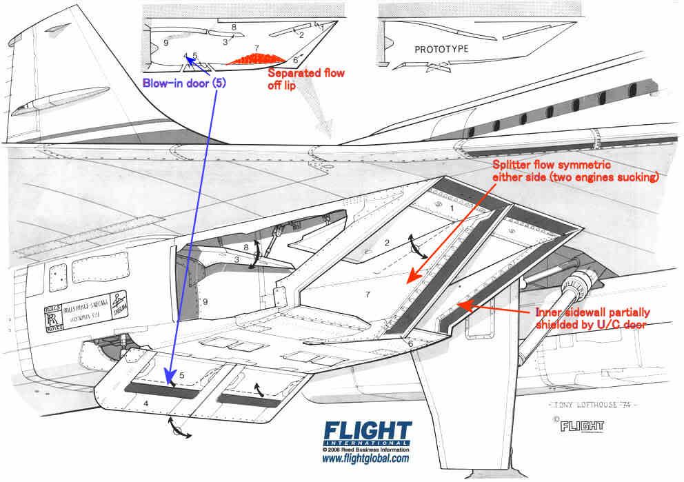
The intake leading edges were all sharp, so the flow would separate if subjected to a high AoA. The upper lip was protected a little by the wing leading edge, and we were obliged to modify the prototype LE ahead of the intakes to prevent underwing vortices developing at low AoA in cruise which also helped a bit.
The lower lip had a substantial separated flow 'bubble' at low forward speed as shown in red, but this cleared up quite quickly as the aircraft gathered speed. It was'cured' by the blow-in doors.
The inner sidewalls were shielded by the landing gear doors, so the AoAs on the sidewall on that side were quite modest.
The splitter was of course subject to equal flow demands on either side so the flow over that was pretty well symmetric.
That leaves the two outer sidewalls which, look for all the world like highly swept delta wings with sharp LEs mounted vertically.
Like all such wings when operated at high AoA they develop powerful vortices on the 'leeward' side. Looking back towards the engine the vortex on #4 engine was anticlockwise and that on #1 was clockwise. [Hope I got that one the right way round ]
]
The OL593 rotates clockwise looking aft so the induced incremental AoA on the compressor blades was different on #1 and #4. The difference was enough to trigger some mild blade vibration - hence the rpm restriction until the intake capture was good enough to reduce the vortex strength.
I don't think there is any published explanation, but maybe this will help.
Basically the problem with #4 intake was that it was on the RHS of the airplane. We are talking about low speed right? and especially zero forward speed when the engine is trying to suck as much air as it can get from wherever it can get it. That means that the induced angle of attack on all the intake leading edges is going to be high.
The best drawing I can find that shows the flow into the right hand pair is this
The intake leading edges were all sharp, so the flow would separate if subjected to a high AoA. The upper lip was protected a little by the wing leading edge, and we were obliged to modify the prototype LE ahead of the intakes to prevent underwing vortices developing at low AoA in cruise which also helped a bit.
The lower lip had a substantial separated flow 'bubble' at low forward speed as shown in red, but this cleared up quite quickly as the aircraft gathered speed. It was'cured' by the blow-in doors.
The inner sidewalls were shielded by the landing gear doors, so the AoAs on the sidewall on that side were quite modest.
The splitter was of course subject to equal flow demands on either side so the flow over that was pretty well symmetric.
That leaves the two outer sidewalls which, look for all the world like highly swept delta wings with sharp LEs mounted vertically.
Like all such wings when operated at high AoA they develop powerful vortices on the 'leeward' side. Looking back towards the engine the vortex on #4 engine was anticlockwise and that on #1 was clockwise. [Hope I got that one the right way round
]
The OL593 rotates clockwise looking aft so the induced incremental AoA on the compressor blades was different on #1 and #4. The difference was enough to trigger some mild blade vibration - hence the rpm restriction until the intake capture was good enough to reduce the vortex strength.