19th Dec 2010, 18:24
permalink Post: 887
Autotrim
It wasn't quite as simple as that. The fuel transfer system really fixed long term problems like getting the elevator trim broadly at optimum throughout (and really at optimum in cruise of course). The Mach trim/autotrim really worked on a shorter timescale to maintain stability at constant CG.
Sure the autopilot made it superfluous to some extent, but to certificate the aircraft it had to be conventionally stable when flow manually, and applying a nose down command to get a speed increase is a basic airworthiness requirement for all aircraft.
Sure the autopilot made it superfluous to some extent, but to certificate the aircraft it had to be conventionally stable when flow manually, and applying a nose down command to get a speed increase is a basic airworthiness requirement for all aircraft.
21st Dec 2010, 13:04
permalink Post: 922
quote:Rolls Royce did some analysis on the flight, and were amazed at how well the propulsion systems coped with some of the temperature sheers that we encountered, sometimes 4 to 5 deg's/second. They said that the prototype AFCS had been defeated by rises of only 0.25 deg's/second ).unquote
Just for the record, the intake control system was designed to cope with a temperature shear of 21 deg C in one mile (about 3 seconds)
quote:Not meaning to go off onto a (yet another) tangent; Negative temperature shears, very common at lower lattidudes, always plagued the development aircraft; you would suddenly accelerate, and in the case of a severe shear, would accelerate and accelerate!! (Your Mach number, quite naturaly, suddenly increased with the falling temperature of course, but because of the powerplant suddenly hitting an area of hyper-efficiencey, the A/C would physically accelerate rapidly, way beyond Mmo). Many modifications were tried to mitigate the effects of severe shears, in the end a clever change to the intake control unit software fixed it. (Thanks to this change the production series A/C would not be capable of level flight Mach numbers of any more than Mach 2.13, remembering that Mmo was set at 2.04).unquote
Not temperature shears, and not AICU modifications (which I see has been discussed in a later posting). But back to the 'shears':
Most of Concorde's flight testing was, naturally, done out of Toulouse and Fairford, i.e. into moderate latitude atmospheres where the tropopause is normally around 36,000 ft so that the supersonic flight testing was done in atmosphers where the temperature doesn't vary with altitude. The autopilot working in Mach hold would see an increase in Mach and apply up elevator to reduce IAS and recover the macg setting. But at the lower latitudes around the equator the atmosphere is different in its large scale characteristics. In particular the tropopause is much, much higher and can get as high as 55,000 ft. Nobody had been up there to see what it was like! Now when the A/P applied up elevator to reduce IAS it went into a region of colder air. But the speed of sound is proportional to air temperature, so as the aircraft ascended the IAS dropped alright but since the ballistic (true) velocity of the aircraft takes a while to change and since the speed of sound had dropped the Mach number was increased, so the A/P seeing this applied more up elevator and the aircraft went up and the speed of sound dropped and ........
Like solving crossword clues, the answer is obvious once you have spent some time finding it!
This phenomenon rather than temperature shears (encountered mainly over the tops of Cb clouds) was the reason for the autopilot modifications which included that clever use of autothrottle (I can use that adjective since it was my French colleagues that devised it)
And before anyone asks; yes, the same problem would relate to subsonic aircraft operating in Mach hold driven by the elevators and flying below the tropopause, but:
a) Subsonic aircraft are old ladies by comparison with Concorde in that they fly at only half the speed. At Concorde velocities even modest changes in pitch attitude can generate some pretty impressive rates of climb or dive!
b) Subsonic aircraft are normally constrained by ATC to fly at fixed flight levels - the use of elevator to control Mach number is not really an option - you have to use an autothrottle.
There was that other problem, also described in later postings, where the aircraft regularly 'rang the bell' when passing through the Vmo/Mmo corner in the lower latitudes, but this was simply due to the additional performance one got in these ISA minus conditions in comparison to the temperatures encountered around the same corner in higher temperatures.
Anyway, the flight test campaign got me my first sight of sunrise over the Arabian desert and my first trip to Asia, so it goes into my Concorde memory bank.
22nd Dec 2010, 08:28
permalink Post: 937
MrVortex
Concorde had triple-axis auto stabilisation, where pilot demands were routed via an AUTOSTAB COMPUTER and summed with any stabilisation demands. There was automatc roll/yaw crossfeed, where for a given roll demand there was a coresponding amount of rudder applied, the amount of which was a function of Mach number. As far as 'dutch roll' etc the autostab system employed rate gyros in the same way as a conventional 'yaw damper' would operate in an inferior
 (oops, my bad.. I mean SLOWER) aircraft.
The AUTOSTAB operated full time, irrespective of AFCS mode. (Perhaps EXWOK, NW1 or one of the other boys will confirm that TURB mode was seldom EVER used in airline service. It was a (if I remember correctly) a Pitch/HDG hold autopilot mode with reduced gain).
Best regards
Dude
Quote:
| I'm wondering that does the auto-stab function in yaw axis does apply some rudder when pilot fly the aircraft by his hand to prevent the sideslip or dutchroll or not? |
(oops, my bad.. I mean SLOWER) aircraft.
Quote:
| Also, does the auto stab does "modify" some pilot input to minimize the effect of the turbulence all the time when airplane encounter the turbulence or only when the AP are in the "TURB" mode? Does it help to reduce the stress on the aircraft like the "load alleviation" on the moder aircraft like A380? |
Best regards
Dude
22nd Dec 2010, 14:50
permalink Post: 941
Quote:
|
Originally Posted by
M2dude
Concorde had triple-axis auto stabilisation, where pilot demands were routed via an AUTOSTAB COMPUTER and summed with any stabilisation demands.
|
Pilot demands in manual flight produced electrical signals corresponding to the control position, which were sent to the 'servo control amplifiers' (eight in all, one per control surface) which in turn commanded the PFCUs (power flying control units) that hydraulically moved the control surfaces.
Autopilot demands directly moved the pilot's controls (stick and rudder) via hydraulic cylinders (the 'relay jacks') so that the same signals as in manual flight then went to the servo control amplifiers.
The purpose of the autostab was to provide proper dynamic stability over the full flight envelope. The aircraft could be flown without autostab, but over some of the speed range it was only marginally stable.
The electrical signals from the autostab computing were fed directly into the servo control amplifiers, so there was no feedback to the pilot's controls, unlike the autopilot demands.
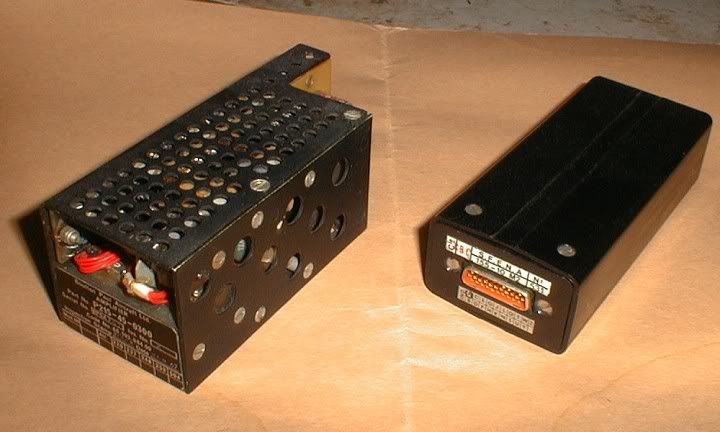
There was occasional confusion about exactly what did what and how and where.... because the servo control amplifiers - although a function independent of the autostab as such - were housed... in the autostab computers.
To complete the tale, this is what those servo control amplifiers look like.
The one of the left is from prototype 002, the one on the right from a production aircraft. To give them scale, the one on the right is about the size of a box of large kitchen/fireplace matches.
CJ
22nd Dec 2010, 15:16
permalink Post: 942
Re TURB mode
That reminds me.....
We spent a lot of time, and did a lot of flights, to get the VOR (capture and hold) autopilot mode to work satisfactorily.
It was not until years later, and on another type, that a pilot told me "VOR mode? We never use it. We use TRK or HDG mode, and monitor on the HSI that we're on the VOR radial."
IIRC, in service it was the same on Concorde, but maybe EXWOK or one of the other pilots here can confirm it?
CJ
Quote:
|
Originally Posted by
EXWOK

I didn't ever use this mode, and never saw anybody else use it.
|
We spent a lot of time, and did a lot of flights, to get the VOR (capture and hold) autopilot mode to work satisfactorily.
It was not until years later, and on another type, that a pilot told me "VOR mode? We never use it. We use TRK or HDG mode, and monitor on the HSI that we're on the VOR radial."
IIRC, in service it was the same on Concorde, but maybe EXWOK or one of the other pilots here can confirm it?
CJ
22nd Dec 2010, 20:40
permalink Post: 951
Before adding my own little bit to Clive's earlier reply about the autotrim, I will try to explain, for those not fully familiar with the subtleties of automatic flight control, the difference between "closed loop" and "open loop".
Closed loop
As an example, let's look (very simplified) at how the autopilot maintains a selected altitude.
On the one hand we have the desired altitude as selected on the autopilot controller (here 40,000 ft).
On the other hand we have the true altitude , as measured by the altimeter (let's say 39,000 ft).
We subtract the two to obtain the altitude error (in this case 39,000-40,000=-1,000 ft).
We 'multiply' the altitude error by a factor, the gain (for the discussion, let's assume this gain is 1 degree elevon per 1000 ft altitude error), and send the resulting elevon position command to the elevon.
So, the elevon moves 1\xb0 nose-up, the aircraft starts to climb, the altitude increases and the altitude error decreases until it becomes zero, by which time the elevon position has also returned to zero.
What we have now is a "closed loop" : any deviation from the selected altitude results in an elevon command in the opposite direction, until the deviation is again reduced to zero.
Another commonly used term is "feedback" : any error is fed back in the opposite sense until it's reduced to zero.
The significant figure here is the 'gain'.
If the gain is too small, the autopilot response to a disturbance (say turbulence) will be sluggish ; the aircraft takes too long to return to the desired altitude.
If the gain is too high, a small disturbance will cause the aircraft to start climbing too rapidly, and to overshoot the desired altitude, then descend to correct the new error, etc.
In other terms, the control loop is no longer stable, but starts to oscillate.
Both theory and practice show that the exact value of the gain is not all that critical, a few percent more or less do not markedly change the response of the loop.
Note: a "closed control loop" as described above can be implemented in just about any way you like.
It can be done purely mechanically, with a few clever clockwork mechanisms 'computing' the altitude error and controlling the elevator pneumatically or hydraulically. It's how the earliest autopilots worked.
After that came electromechanical systems, analogue computers and then digital computers... but the principle has remained unchanged.
Open loop
As already described in earlier posts, the situation with the automatic trim is the opposite.
We now need to compute a neutral elevon position from several data, such as Mach number or airspeed, but without any feedback as to whether our computations are correct.
We're now working in "open loop".
To complicate matters... that neutral elevon position is not a simple linear function of Mach and airspeed, but far more complex (see the earlier posted graphs).
And because of the large response of the aircraft to small changes in trim, in particular in the transonic regions, those computations have to be far more accurate : a one degree error is simply not acceptable.
In the end.....
The AICS (air intake control system) also uses several "open loop" functions.
The early development aircraft still had an analogue system, which proved all too soon to be inadequate, so, at a very late stage, it was replaced by a digital system (one of the rare digital systems on Concorde).
The "open loop" functions of the autotrim system initially had the typical "a few" percent" accuracy of the other flight control systems, which, for the autotrim, also proved inadequate.
We managed to "save the furniture" (as they say in French) by using 0.1% components in all the critical computing paths, so the autotrim computers remained analogue until the end.
But, a slide rule is not accurate to 0.1%... So that's when I had to buy my very first pocket calculator.
\xa342 at 1972 prices... just as well the firm paid.
CJ
29th Dec 2010, 23:03
permalink Post: 1048
Quote:
|
Originally Posted by
Landroger
Between you, you have just about created a 'flash time machine'. An instant image of a real day and a real moment. I'll admit that though I looked at Bellerophon's picture with some care, it was only by reading his text that the image began to make some sense. Then along comes Exwok, casts his eyes over the image and suddenly we are squinting in the glare of high altitude sunlight and listening to the sound of the machine as she arcs across the sky, entirely comfortable with her environment and eye watering pace. Thank you both.
|
To most people, a Concorde cockpit is just a bewildering array of 'clocks' and other bits.
People like Bellerophon and Exwok read it all in seconds.
Even an ancient like me, seeing a cockpit photo, instantly recognises a museum photo, because of the toppled emergency horizon, or because of the odd bits and pieces we used on the autopilot controller on G-AXDN (01).
Quote:
| ..only 97 people have flown Concorde including two women? |
Unless you also include Jacqueline Auriol, probably the world's first female test pilot, who flew Concorde 001 in the earliest days.
Quote:
| It is clear from this fabulous thread that the passing of Concorde has left an aching void in the lives of the contributors here. |
Speaking for myself, no, it's not a void, it's a highlight, that I now like passing on, in the hope other generations will find inspiration in the 'Concorde Story' for their own endeavours.
Christian
7th Jan 2011, 13:13
permalink Post: 1079
The thar intakes
Clive & Christian
Gentlemen, I think you will find that 102 did indeed have a totally 'unique' analog intake control system. Not only were the RDCUs (not AICUs in this case chaps) totally different, there were major architectural changes over the prototype system too. Also, although the basic intake structure was the same as 101 and all subsequent aircraft, there was still the prototype approach to local pressure sensing adapted, ie. Intake face total pressure P∞ sensed directly via the infamous 'magic holes' rather than using digitally synthesised values based on mainline aircraft manometric probe, total (pitot)pressure. As 101's intakes only went 'live' in mid-march 1973, I assumed that maybe they (AS) wanted an operative intake system from the outset on 102 when it first flew in January of that year. What puzzled me was why they went for this seemingly enhanced (and expensive) analog system on 102 and not the original system. (As 102 used a production type intake, I guess that they would have to have at least made some changes to the control system ; there was no exotic double hinged 'Dump Door', but the far simpler and elegant 'Spill Door' with integral Aux' Inlet Vane that was known and loved by us all). Rumour had it that AS still wanted to pursue the 'magic holes' solution and were dead against the decision to go digital. (This particular decision was taken in October 1970, which makes the 102 AICS route seem all the more strange).
And ChristiaanJ; what you guys achieved with the MAX CLIMB/MAX CRUISE was nothing short of remarkable. Just about the most exotic (and complex) autopilot mode that I've ever seen, that solved so MANY problems. (Still the only A/P mode I've ever seen where the Autothrottle is engaged in a speed mode at the same time as the AUTOPILOT
 ).
).
Best regards
Dude
Gentlemen, I think you will find that 102 did indeed have a totally 'unique' analog intake control system. Not only were the RDCUs (not AICUs in this case chaps) totally different, there were major architectural changes over the prototype system too. Also, although the basic intake structure was the same as 101 and all subsequent aircraft, there was still the prototype approach to local pressure sensing adapted, ie. Intake face total pressure P∞ sensed directly via the infamous 'magic holes' rather than using digitally synthesised values based on mainline aircraft manometric probe, total (pitot)pressure. As 101's intakes only went 'live' in mid-march 1973, I assumed that maybe they (AS) wanted an operative intake system from the outset on 102 when it first flew in January of that year. What puzzled me was why they went for this seemingly enhanced (and expensive) analog system on 102 and not the original system. (As 102 used a production type intake, I guess that they would have to have at least made some changes to the control system ; there was no exotic double hinged 'Dump Door', but the far simpler and elegant 'Spill Door' with integral Aux' Inlet Vane that was known and loved by us all). Rumour had it that AS still wanted to pursue the 'magic holes' solution and were dead against the decision to go digital. (This particular decision was taken in October 1970, which makes the 102 AICS route seem all the more strange).
And ChristiaanJ; what you guys achieved with the MAX CLIMB/MAX CRUISE was nothing short of remarkable. Just about the most exotic (and complex) autopilot mode that I've ever seen, that solved so MANY problems.
(Still the only A/P mode I've ever seen where the Autothrottle is engaged in a speed mode at the same time as the AUTOPILOT
).
Best regards
Dude
Last edited by M2dude; 8th Jan 2011 at 09:58 . Reason: 'All I want for Christmas is the ability to spell'
16th Jan 2011, 06:52
permalink Post: 1109
Quote:
| How was the mechanical system 'de-coupled' from the electrical channels thus that any movement from the control column was 'ignored' by this channel ? |

In mechanical back-up control demands were fed to relay jacks which acted as force amplifiers so the pilot was unaware of control run friction. The autopilot also fed into these relay jacks. This meant that the control precision and ability to harmonise control forces given by the electrical control system was not degraded by mechanical system shortcomings.
In electrical signalling there was a dead space at the Powered Flying Control Units (PFCU) to allow for the difference between mechanical and electrical commands produced by autostabiliser activity. Variation of this dead space with flight condition gave the autostabiliser authority limits. Autostab. was not available in mechanical signalling when the PFCU servo valve was locked to the mechanical control system.
So the control column movements were never 'ignored' by either system, but the mechanical system never 'saw' the autostabiliser commands.
Cheers
Clive
16th Jan 2011, 09:41
permalink Post: 1110
SpeedbirdConcorde
Hi again my friend. To further expand on CliveJ's superb explanation: Mechanical control inputs were fed to each of the 8 Powerd Flying Control Units (PFCUs), but in electronic signalling (either Blue or Green) these inputs were de-clutched at the PFCU input lever. When Fly By Wire' signalling is not available, the mechanical inputs (which as CliveL quite rightly points out) are driven by the Relay Jacks, now are locked to the input lever and can now move the input jack of the PFCU (known as the spool valve) and subsequently cause the PFCU to drive the control surface. (The body of the PFCU moved, the main jacks were attached at each end to structure and so obviously did not move). Hopefully this diagram will help visualising the process a little easier:
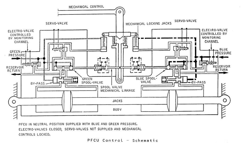
The diagram shows Green & Blue hydraulics supplied but the electro-valves (opened by the respective FBW channel) are both closed. You can see that the mechanical input lever is 'locked' to the PFCU input lever which will drive the SPOOL VALVE directly. When FBW is enabled, either the Blue or Green (never both together) ELECTRO-VALVE are signalled open, the ensuing hydraulic pressure then pushing the input clutch upwards and disengaging the mechanical input. FBW demands are now fed to the respective SERVO VALVE which will hydraulically send the SPOOL VALVE in the desired direction.
The Relay Jacks could be considered to be a little like a PFCU (you had 2 RJs per axix) but instead of the servo valves being driven by the FBW system they were driven by the autopilot and instead of driving a control surface, they drove the control runs. In manual flight the input spool was driven via a mechanical input lever, which would drive the RJ spool a little like Mech' signalling drove the PFCU spool. In A/P mode the mechanical input rod was de-clutched \xe0 la PFCU, but (and here's the clever part) this input was locked to the body of the Relay Jack which when it moved, drove the pilot's control in sympathy. (Control column, yoke or rudder pradals). As the respective control(s) was moved by the Relay Jack, the corresponding FBW position sensor (resolver) would change position and generate the FBW demand. (As the surface moved there was a feedback resolver at PFCU level).
As far as the FBW channels themselves went; there were 2 electronic signalling modes, Blue and Green, sub-divided into 3 groups (Inner Elevons, Outer & Mid Elevons and Rudders). Each group was independently monitored, and a fault in say the Rudder channel alone, would result in the rudders ONLY changing lanes. NOW ( ), The normal control channel was BLUE, and if this failed you would drop the respective channel into GREEN and if this failed you would drop into MECH. The selector switches (1 per group) enabled you to select BLUE/GREEN/MECH in that order. If for some reason you were selected to GREEN, a failure of that signalling lane would not drop you 'up' into BLUE, but into MECH. Your switch would only be in this position if you'd had a problem with BLUE, however you would select this on pushback while you were testing the flying controls, otherwise you spent your whole life selected to BLUE. As far as BA went, I can never remember a time personally when all 3 groups dropped from BLUE to MECH, but very rarely you might get a fault that caused a single group to briefly drop to MECH. Just about one of the very few common mode failures to each of the 3 groups would be a failure of the respective FBW static inverter. This thing, which was rightly monitored up to the hilt, produced a 26 Volt 1800 Hz output. (1800 Hz was chosen as this is not a harmonic of aircraft mainline 400 Hz AC supply)
Best regards
Dude
Hi again my friend. To further expand on CliveJ's superb explanation: Mechanical control inputs were fed to each of the 8 Powerd Flying Control Units (PFCUs), but in electronic signalling (either Blue or Green) these inputs were de-clutched at the PFCU input lever. When Fly By Wire' signalling is not available, the mechanical inputs (which as CliveL quite rightly points out) are driven by the Relay Jacks, now are locked to the input lever and can now move the input jack of the PFCU (known as the spool valve) and subsequently cause the PFCU to drive the control surface. (The body of the PFCU moved, the main jacks were attached at each end to structure and so obviously did not move). Hopefully this diagram will help visualising the process a little easier:
The diagram shows Green & Blue hydraulics supplied but the electro-valves (opened by the respective FBW channel) are both closed. You can see that the mechanical input lever is 'locked' to the PFCU input lever which will drive the SPOOL VALVE directly. When FBW is enabled, either the Blue or Green (never both together) ELECTRO-VALVE are signalled open, the ensuing hydraulic pressure then pushing the input clutch upwards and disengaging the mechanical input. FBW demands are now fed to the respective SERVO VALVE which will hydraulically send the SPOOL VALVE in the desired direction.
The Relay Jacks could be considered to be a little like a PFCU (you had 2 RJs per axix) but instead of the servo valves being driven by the FBW system they were driven by the autopilot and instead of driving a control surface, they drove the control runs. In manual flight the input spool was driven via a mechanical input lever, which would drive the RJ spool a little like Mech' signalling drove the PFCU spool. In A/P mode the mechanical input rod was de-clutched \xe0 la PFCU, but (and here's the clever part) this input was locked to the body of the Relay Jack which when it moved, drove the pilot's control in sympathy. (Control column, yoke or rudder pradals). As the respective control(s) was moved by the Relay Jack, the corresponding FBW position sensor (resolver) would change position and generate the FBW demand. (As the surface moved there was a feedback resolver at PFCU level).
As far as the FBW channels themselves went; there were 2 electronic signalling modes, Blue and Green, sub-divided into 3 groups (Inner Elevons, Outer & Mid Elevons and Rudders). Each group was independently monitored, and a fault in say the Rudder channel alone, would result in the rudders ONLY changing lanes. NOW ( ), The normal control channel was BLUE, and if this failed you would drop the respective channel into GREEN and if this failed you would drop into MECH. The selector switches (1 per group) enabled you to select BLUE/GREEN/MECH in that order. If for some reason you were selected to GREEN, a failure of that signalling lane would not drop you 'up' into BLUE, but into MECH. Your switch would only be in this position if you'd had a problem with BLUE, however you would select this on pushback while you were testing the flying controls, otherwise you spent your whole life selected to BLUE. As far as BA went, I can never remember a time personally when all 3 groups dropped from BLUE to MECH, but very rarely you might get a fault that caused a single group to briefly drop to MECH. Just about one of the very few common mode failures to each of the 3 groups would be a failure of the respective FBW static inverter. This thing, which was rightly monitored up to the hilt, produced a 26 Volt 1800 Hz output. (1800 Hz was chosen as this is not a harmonic of aircraft mainline 400 Hz AC supply)
Best regards
Dude
Last edited by M2dude; 16th Jan 2011 at 12:10 . Reason: Clarity; Oh for clarity
28th Jan 2012, 23:46
permalink Post: 1547
Da-20 monkey
No, there were no trim tabs on Concorde.
Yes, just so.
Concorde had conventional trim controls (electric trim in pitch, manual in roll and yaw), but operating a trim control merely changed the artificial feel datum position and thus the neutral position of the flying controls.
The electric pitch trim not only operated automatically whenever an autopilot was engaged, but could and would also operate automatically in manual flight, independently of any pilot input, to provide pitch stability corrections in various situations.
Best Regards
Bellerophon
Quote:
| ... Does concorde have real trim tabs?... |
Quote:
| ...is it just an artificial feel unit that changes the neutral point in the stick?... |
Concorde had conventional trim controls (electric trim in pitch, manual in roll and yaw), but operating a trim control merely changed the artificial feel datum position and thus the neutral position of the flying controls.
The electric pitch trim not only operated automatically whenever an autopilot was engaged, but could and would also operate automatically in manual flight, independently of any pilot input, to provide pitch stability corrections in various situations.
Best Regards
Bellerophon
15th May 2012, 10:03
permalink Post: 1631
The TAT thing
Quote:
|
OK, so the skin temperature at the stagnation point will be equal to TAT. This can be taken as the hottest part of the aircraft (behind it, the skin temperature will be less than the TAT).
The temperature shown in the top window of the flight deck gauge is TAT, with the legend 'TMO 128C' beneath it. So the aircraft was flown with reference to TAT, and provided TAT was no greater than 128C then the skin rearward of the stagnation point would be <128C? |
MACH 0.5 . ISA -5: TAT = -50.6 \xb0 C . ISA: TAT = -45.3 \xb0 C. ISA +5 TAT = -40 \xb0 C
MACH 1.0 . ISA -5: TAT = -18.5 \xb0 C . ISA: TAT = -12.5 \xb0 C. ISA +5 TAT = -6.5 \xb0 C
MACH 1.5 . ISA -5: TAT = 34.8 \xb0 C . ISA: TAT = 42 \xb0 C. ISA +5 TAT = 49.3 \xb0 C
MACH 2.0 . ISA -5: TAT = 109.5 \xb0 C . ISA: TAT =118.6 \xb0 C. ISA +5 TAT = 127.6 \xb0 C
Hopefully it all makes a little more sense with some 'real' numbers. You can see that as Mach Number increases the gap between SAT and TAT increases hugely. The Mach 2, ISA +5 case was particularly significant for Concorde, as it breached the 127 \xb0 C/400 \xb0 K airframe temperature limit (TMO) and Mach Number would therefore be automatically reduced by the autopilot. (An overspeed warning would be generated at TMO +7 (134. \xb0 C). Fortunately sustained ISA +5 or above conditions were relatively rare over the North Atlantic but not unheard of either.
Last edited by M2dude; 16th May 2012 at 23:06 . Reason: ISA+5 Typo
17th May 2012, 12:05
permalink Post: 1632
INS
stilton
Actually not technically correct mate. The generation(s) of aircraft after Concorde does not use INS as such at all. They either use an Inertial REFERENCE System (IRS) or an Air Data and Inertial Reference System (ADIRS). In both cases inertial data, such as attitude, present position, heading (both true and SYNTHESISED magnetic) acceleration data etc. are output to various user systems. (eg. FMS, EFIS, Autopilot etc.). Wind data, being a function of True Air Speed (TAS) and Ground Speed (G/S)requires in the IRS case TAS data to be input into the IRS from an Air Data Compter, whereas in the ADIRS case we can have muliple ADCs/IRUs effectively crammed into one box, and so wind is kept 'in house'. In either case the autopilot steering signals (LNAV/VNAV) come from the FMS and NOT the IRS. (If you like you could say that an INS knows where it is and where it wants to go, where an IRS just knows where it is and hasn't a CLUEwhere it's going to. In all cases GPS data is fed into the FMS itself, as 'just another input'.
Although Concorde HAD no GPS, (The most difficult part was always finding a part of the upper fuselage where chunks could be cut out for locating antennae) it was coming! EGPWS was being mandated, which required a simplex GPS antenna mount, and GPS updating for the INS was being seriously looked at. In the first case, the EGPWS requires accurate present position to check agaings it's terrain database for known obstacles and the latter case was because the Concorde INS navigational accuracy fell outside of future (now actually) long range navigational accuracy requirements.
Sorry for such a long winded blurb, but I've been away for a while and am gradually looking back over our wonderful thread to see if there is anything I can contribute to/prattle on about.
Quote:
|
All modern jet transports still use INS, it's output is used for more than just navigation, e.g. Attitude indicator, vertical speed input and others.
GPS (and other sources) merely update and refine the INS position. I am sure Concorde would have done the same. |
Actually not technically correct mate. The generation(s) of aircraft after Concorde does not use INS as such at all. They either use an Inertial REFERENCE System (IRS) or an Air Data and Inertial Reference System (ADIRS). In both cases inertial data, such as attitude, present position, heading (both true and SYNTHESISED magnetic) acceleration data etc. are output to various user systems. (eg. FMS, EFIS, Autopilot etc.). Wind data, being a function of True Air Speed (TAS) and Ground Speed (G/S)requires in the IRS case TAS data to be input into the IRS from an Air Data Compter, whereas in the ADIRS case we can have muliple ADCs/IRUs effectively crammed into one box, and so wind is kept 'in house'. In either case the autopilot steering signals (LNAV/VNAV) come from the FMS and NOT the IRS. (If you like you could say that an INS knows where it is and where it wants to go, where an IRS just knows where it is and hasn't a CLUEwhere it's going to. In all cases GPS data is fed into the FMS itself, as 'just another input'.
Although Concorde HAD no GPS, (The most difficult part was always finding a part of the upper fuselage where chunks could be cut out for locating antennae) it was coming! EGPWS was being mandated, which required a simplex GPS antenna mount, and GPS updating for the INS was being seriously looked at. In the first case, the EGPWS requires accurate present position to check agaings it's terrain database for known obstacles and the latter case was because the Concorde INS navigational accuracy fell outside of future (now actually) long range navigational accuracy requirements.
Sorry for such a long winded blurb, but I've been away for a while and am gradually looking back over our wonderful thread to see if there is anything I can contribute to/prattle on about.
30th Nov 2012, 15:22
permalink Post: 1693
A couple of questions
Hi all, amazing thread! I hope I can add a couple of autopilot questions:
1. Did anyone ever use the IAS Hold button in the vertical mode, i.e. control speed with pitch instead of autothrottle? I always thought it might be used during climbout to maintain 250 knots under 10000 feet at full throttle.
2. How did the autopilot work in 'Go Around' mode and was it ever used, or were go arounds always done manually?
Thanks in advance,
Jim
Last edited by taichi40; 30th Nov 2012 at 15:37 .