22nd Aug 2010, 12:29
permalink Post: 65
 Galaxy Flyer
Quote:
| One more question, could the Concorde lose pressurization, descend to some low level (FL180 or below, perhaps FL100) and make it to scheduled destination or would a divert to Shannon or Gander be required? What was a low level cruise speed? |
It's great that Bellerophon is posting here again; we need a steely eyed Concorde pilot's input here (not just the boffins/nutters and nerds [that's me
 ]. To touch more on a couple of his valid points;
Fuel burn: The aircraft would naturally require less fuel as she became lighter and as a consequence gently climbed to maintain cruise Mach number, this is what the engine control system was doing all the time, even though the throttles were wide open it was 'tweaking'.. BUT, the decreasing IAS as you climbed, due of course to the reducing density, just like any other aircraft meant that drag was reducing too, so it was a combination of both of these factors, reducing weight and reducing drag.
Flying controls: It was a slightly weird but wonderful arrangement; pilots inputs would move a servo valve in the hydraulic relay jack, the jack would move in response and drive both a resolver AND mechanical linkages. The resolver ourput was sumed with the flying control position resolvers, and the error signal was fed into an autostab' computer, where it was summed with stabilisation demands (primarily axis rate and acceleration). The autostab computer would the directly drive the surface, and the reducing error signal would reduce the demand etc. While all this was going on, the mechanical linkages would slavishly follow, but as long as you were in FBW (what we used to call 'signalling') mode, these mechanical inputs were de-clutched at the PFCU, so did nothing at all. Only if there was an EXTREMELY unlikely failure of BOTH FBW channels would these inputs be clutched in and the flying control group (rudders, inner elevons or outer and mid' elevons) would then be in Mechanical signalling. The system redundancy was checked after engine start on every flight. But to reinforce what Bellerophon stated, there was no mechanical reversion here; without hydraulics you had nothing. Another aside here; the designers, being paranoid like all good designers (no offence Christiaan
 ) were worried what would happen if the controls would somehow jam up. A jammed mechanical flying control input run itself would have no effect on FBW operation whatsoever, due to spring boxes being fitted to the runs. A 'Mech Jam' light would be set, together with a separate red light and audio warning, but this was all. But to completely protect against the aircraft was fitted with a Safety Flight Computer (SFC) system. The idea was, if a control axis (pitch or roll only) jammed up, the captain could press down on a switch light set between the two halves of his control wheel, (at the centre of the 'W') and the Emergency Flight Controls would activate. Strain gauges at the front of the control wheel, two sets on each control column for pitch and roll axis, would input into an SFC that would covert the control force into an elevon demand. These commands were then fed into the autostab' computers, and hence directly into the controls. (A little like L-1011 CWS in a way). There was a little test button that was used to test this system, again after engine start. So although the controls were jammed, the aircraft could still be flown. (Never used in anger I'm pleased to report).
But there was a problem; if this system was inadvertantly used, the results could have been catastrophic, as the system was extremely sensitive indeed, and full elevon movement could be enabled with only moderate effort. Because of this hairy prospect some safeguards were obviously put in place. The first safeguard was an interlock in the autostab' engage logic; If the switchlight had been inadvertently selected beforehand (the light was green by the way) you would not be able to engage pitch or roll autostab's (both channels too) so you would not be going flying until that was fixed. The second safeguard was a little more subtle; A plastic, frangible cover was fitted over the switchlight, unless the captain pressed reasonably hard the cover would prevent the switchlight from being pressed. At least that was the theory, in practice this little bit of plastic could be a pain in the ass
 . It was carefully fashioned, and I seem to remember BAe charging the airlines a few hundred pounds each for these things. If some wally fitted the cover upside down (and unless you were careful it was easy to do) THE THING WOULD NOT BREAK!! I remember at Fairford in 1976, G-BOAD was on pre-delivery flight testing, and the late great test pilot John Cochrane was doing a test of the system. The cover on this occasion HAD been fitted upside down, and of course he could not plunge his thumb through it and engage the EFC button. After trying everything, in the end he removed a shoe, took out his pen, and smashed the plastic cover until it broke. (It's OK, the autopilot was engaged at the time). Unfortunately, his combined shoe/pen emergency device also wrecked the switchlight as well, so the system still could not engage. (There was only a switchlight on the captain's side). After he landed and he confronted us all with his dilemma, he was shaking; not with rage but with laughter. (This was the great John Cochrane, sometimes the dour Scotsman but he was always able to see the lighter side). After that event, careful instructions were issued regarding the fit of the cover, and it was modified and made a little more frangible.
Last edited by M2dude; 23rd Aug 2010 at 00:02 . Reason: will engineers ever learn to spell?
23rd Aug 2010, 18:49
permalink Post: 85
yoke feedback
Biggles:
Yep, there was feedback. In this respect, the implementation of FBW had a rather different philosophy to FBW Airbus'.
Below 200kts it was basically a spring feedback, above that speed it was achieved throught the feel system, not entirely unlike conventional aircraft.
Of course, the feel was tempered also by the autostab system, which didn't feedback through the yoke, but did make control surface inputs. A basic analogy is to imagine a yaw damper, but on all three axes. (It was of course rather more sophisticated, especially in pitch).
During airtests we would fly portions of the supersonic accel without autostabs and it was then very obvious exactly how much input was being made - great care was needed to remain within sensible bank angles in the low supersonic regime.
Also - watch a video of the control surfaces in the latter stages of the approach and landing - all those rapid deflections are the autostabs overlaid on the pilot's inputs. One has to remember that the aircraft is effectively statically unstable in pitch at approach speeds, so a pilot up-elevator input would soon be followed by a countering autostab elevon-down to contain the tendency to keep pitching up, and vice-versa. Gusts affecting the IAS would also create an input.
All of which means the basic spring feel below 200kts is not as basic as it sounds.....and in normal signalling modes (ie FBW and autostab active) the amazing thing is that the aircraft handled beautifully through an 1100kt speed range.
If you look at a picture of the flightdeck you will see a row of 14 white switches full width of the fwd edge of the overhead panel. These were autostab pitch/roll/yaw, feel pitch/roll/yaw left and right systems and the two pitch trim switches (which played a big part in the low-speed protection).
If any of them dropped out you could be sure that the first thing the nearest pilot would do would be to try to re-engage them, as it made for a vastly more pleasant life.
25th Aug 2010, 23:04
permalink Post: 123
Quote:
|
Originally Posted by
Landroger

I'm a bit embarrassed about missing that multi pin socket on the AICU board.
I somehow thought it was a specific function chip or a development test socket. Some of those used to appear and remained on some of our boards.
|
Could be Autostab, Lateral Autopilot or Trim, since they all used exactly the same technology, board size, etc.
Looking at the board, I think it's 'Lat A/P' but I can't be certain.
No excuse needed about missing the "central connector" !
It was really a "one-off" feature, invented by Bendix, and abandoned afterwards. I'm not even sure the early A300B AFCS computers, that used much of the Concorde technology, still had them.
Quote:
| I just noticed DozyWannabe's question about core memory. I guess it would have been core... |
CJ
26th Aug 2010, 16:43
permalink Post: 132
Quote:
|
Originally Posted by
Brit312
Surges were not an uncommon or common event on Concorde, but when they happened - as they usually affected both engines on that side - the aircraft would lurch /yaw and everybody on board would know about it...
|
So the prototypes were equipped with "autorudder" computers. They used pressure sensors in the engines to detect engine failures, and they would then kick in a "pre-dosed" amount of rudder, that would then be "washed-out" gradually while the pilot dealt with the issue and added rudder trim.
They were manufactured by SFENA, and since I was their flight test support at Fairford, they became automatically my "babies".
The computers (analog, big boxes, the same size as the autopilots or air intake computers) were extremely reliable (we had only two passive faults during the entire flying career of 002).
Unfortunately the same could not be said of the pressure sensors, and since it was always easier to "pull" a computer than a pressure sensor, we found a computer on the bench every few weeks, which then had to be taken through a full test spec and sent back with "no fault found", before anybody was willing to look at the sensors.
Luckily a better solution was found, using a lateral accelerometer, and from the preprod aircraft onwards, each big separate autorudder computer was replaced by a single board tucked away in the autostab computer.
Since the function was always "on", there was no separate autorudder engage switch. Many years later, I discovered that several airline Concorde pilots did not even know the function existed....
CJ
27th Aug 2010, 04:59
permalink Post: 133
Nick Thomas
[QUOTE]Going back to expansion and paint. With the aircraft expanding approx 6 inches and a temp change up to 127`c, I guess a special kind of paint; able to withstand such adverse conditions; must have been used? When deciding on the paint specification was any consideration given to the overall weight of the paint?[/QUOTE
Can't remember much about paint spec's, but a lot of experimentation/trial and error was carried out with different paints until the right one was found. I remember when G-BOAD was delivered, that copiuous sheets of paint had peeled off in flight. Finally a superb polyurithane paint was found that did the trick perfectly.
Yes Nick, the life of the airframe was limited by the number of supersonic cycles, however modifications carried out extended the life of the airframe significantly. (and more were planned).
And the 'hat in the gap' stories are quite true.
ChristiaanJ
This was the real beauty of the autostab' on all 3 axis; you could just safely take it all for granted. The Mach 2 engine out case was a classic, as not only would the aircraft yaw towards the dead engine but there was an adverse roll input, where the wing on the same side would LIFT due to the excess intake air for the failed automatically being 'dumped' through the now open spill door. If for any reason the aircraft HAD been under manual rather than autopilot control, then life without autostab would be rather uncomfortable to say the least. And putting further Concorde's achievements in terms of stability; the world's only previous large delta winged Mach 2 aircraft, the B58 Hustler, had the slightly awkward feature in the case of an outer engine failure at Mach 2, in that the yaw forces were sufficient to tear the fin off. This happened on more than one occasion during service life of the Hustler, but engine failure (or far more likely a deliberate precautionary shut-down) although hardly a non-event in the case of Concorde, it was routinely dealt with without drama or danger.
Dude
[QUOTE]Going back to expansion and paint. With the aircraft expanding approx 6 inches and a temp change up to 127`c, I guess a special kind of paint; able to withstand such adverse conditions; must have been used? When deciding on the paint specification was any consideration given to the overall weight of the paint?[/QUOTE
Can't remember much about paint spec's, but a lot of experimentation/trial and error was carried out with different paints until the right one was found. I remember when G-BOAD was delivered, that copiuous sheets of paint had peeled off in flight. Finally a superb polyurithane paint was found that did the trick perfectly.
Quote:
| Did the repeated expansion and contraction cycle have a detremental effect on the ulitamate life of the airframe? |
And the 'hat in the gap' stories are quite true.
ChristiaanJ
Quote:
| Many years later, I discovered that several airline Concorde pilots did not even know the function existed.... |
This was the real beauty of the autostab' on all 3 axis; you could just safely take it all for granted. The Mach 2 engine out case was a classic, as not only would the aircraft yaw towards the dead engine but there was an adverse roll input, where the wing on the same side would LIFT due to the excess intake air for the failed automatically being 'dumped' through the now open spill door. If for any reason the aircraft HAD been under manual rather than autopilot control, then life without autostab would be rather uncomfortable to say the least. And putting further Concorde's achievements in terms of stability; the world's only previous large delta winged Mach 2 aircraft, the B58 Hustler, had the slightly awkward feature in the case of an outer engine failure at Mach 2, in that the yaw forces were sufficient to tear the fin off. This happened on more than one occasion during service life of the Hustler, but engine failure (or far more likely a deliberate precautionary shut-down) although hardly a non-event in the case of Concorde, it was routinely dealt with without drama or danger.
Dude
2nd Sep 2010, 23:55
permalink Post: 192
Hi canuck slf, Your incident was not the hydraulic contamination one, I'll describe that one in a minute or so below.
As far as your adventure goes, in the early days of Concorde operation there was an on-going issue of hydraulic seal failures. This led to the sort of thing that you described, where a major seal failure would occur, resulting in the loss of a main system. The standby Yellow system would be switched in to replace the failed one, and depending on the nature of the initial failure, could leak out of the same failed seal. (There were a couple of 'common areas', they were the intake spill door jack, and the Powered Flying Control Units; failures here could result in a double system fail). Your incident was almost certainly due to one of these cases. In the early 1990's the original Neoprene hydraulic seals were replaced with a new Viton GLT seal; this material had far superior age shrinking characteristics to Neoprene, and more or less cured the problem overnight. Eventually all the seals in each aircraft were replaced, and apart from a very few isolated cases, dual system losses were eliminated forever. Air France suffered a similar proportion of failures, however as their flying hours were a fraction of BA's, the effects were not as immediately apparent.
As far as far as the hydraulic contamination story goes, this happened in 1980 but involved one aircraft only, G-BOAG, but in it's original registration of G-BFKW. (having previously been on loan from British Aerospace, where it flew originally as a 'white tail' under this registration). The fragile nature of Concorde hydraulic fluid was not fully understood at this time, and as you say, a hydraulic drum dispenser had inadvertently been left exposed to the atmosphere, and had subsequently suffered water contamination, and this contaminated fluid had found it's way into G-BOAG. Now this hydraulic fluid, CHEVRON M2V has only two vices: One is that is extremely expensive, and the second is that it is highly susceptible to water contamination, EXTEMELY SO. If my memory serves me correctly, the maximum allowable level of water in the fluid is about 8ppm. (parts per million) and the fluid that was analysed after G-BOAG's problems was at about 30 ppm. The water deposits in the fluid gave the equivalent effect of 'rusting up' of critical hydraulic components. I was investigating an air intake control defect the previous day to the incident, but like everybody else had no idea that the real issue here was one of major systems contamination. We were all convinced that we had nailed the problem, only to find that the aircraft turned back on it's subsequent LHR-JFK sector with more serious problems, not only affecting the air intakes, but the artificial feel system also. It was now that we realised that there had to be a hydraulics problem here, and after fluid analysis, the awful truth was discovered. After this event, and the fragilities of M2V fluid were better understood, a strict regime of housekeeping was put in place in terms of fluid storage, and no such incidents with BA ever occurring again. The aircraft itself did not fly again for nine months, all components that were affected were removed from the aircraft and completely stripped and overhauled. Also all of the system hydraulic lines had to be completely purged, until there were no further traces of any contamination. After the aircraft was finally rectified, she successfully again returned to service with her new 'BA' registration of G-BOAG. However the following year, during a C Check, it was decided that due to spares shortages, and the closure of the LHR-BAH-SIN route, there just was not being enough work for seven aircraft, and therefore G-BOAG would be withdrawn from service. (In terms of spares, BA at the time for instance only had six sets of aircraft galleys, as aircraft went in for C checks the galley was 'robbed' to service the aircraft coming out of it's own C check). The aircraft was parked in a remote hangar, and was only visited when a component had to be 'robbed' for another Concorde, and the aircraft soon fell into disrepair, was filthy externally and became a really sad sight. Many people (not myself I might add) were adamant that G-BOAG would never fly again. However, in 1984 things had really started to improve for Concorde, with the charter business increasing and the LHR-JFK route in particular becoming a staggering success. It was decided that OAG would be returned to an airworthy condition. In 1985, with a fresh new interior, and with the new BA colour scheme, she was finally returned to service; and remained as one of the mainstays of the fleet right up to the end of Concorde services in October 2003. She now resides at the Boeing Museum of Flight in Seattle. (I have particularly fond memories of G-BOAG; in a previous post I mentioned flying through an electrical storm in late 1991 over Saudi Arabia, while returning from BKK-BAH to LHR. What I forgot to mention was the spectacle of DOZENS of fierce fires burning on the ground, towards our starboard horizon. These were Sadams oil fires, still burning in Kuwait. It made a sombre contrast to the amazing electrical spectacle right in front of us).
As far as low speed flying control activity was concerned, this was a combination of the fairly flexible outer wing sections, being buffeted by low speed turbulence (the wing tip tanks 5A & 7A also being empty), as well as some autostab inputs. This was perfectly normal, and part of the design our aircraft. However the development aircraft had even more flexible outer wing sections, which used to almost straighten up in high speed flight. However due to fatigue concerns, external lateral stiffeners were added to the underside of the wings during production of the airline aircraft. (these can be easily seen from underneath the wings, just outboard of the nacelles). Unfortunately these external stiffeners also resulted in over a one tonne fuel penalty to the production aircraft, due to increased weight, as well as higher drag in a critical part of the wing aerodynamic surface.
Dude
Last edited by M2dude; 3rd Sep 2010 at 00:07 .
28th Sep 2010, 21:45
permalink Post: 484
It was a delight to hand fly supersonic. With autostabs working it was a pleasure to fly through the whole regime, although from M0.95 to about M1.3 it was a bit squirmy - as though someone kept playing with the trims.
Take-off was flown without flight directors as there was no AFDS mode which suited the juggling of roc vs acceleration. If the AP was going to be used them one Usually hand-flew without fly director until you got to the barbers pole when Max Clb could be engaged on FD and AP. mostly we'd just use the FD and hand fly to the subsonic crz.
It really was a very hands on aeroplane - probably the last type out of LHR where one routinely tracked NDBs and VORs every departure (via CPT) without the aid of a flt director let alone a moving map!
Which is one of the many reasons we all loved flying it!
PS pls excuse all the shpelling mishtooks - am using a tiny touchscreen keyboard.....
28th Sep 2010, 22:03
permalink Post: 487
Quote:
|
Originally Posted by
EXWOK
It was a delight to hand fly supersonic. With autostabs working it was a pleasure to fly through the whole regime...
|
I was involved with tweaking the autostabs in those very earliest days... and it's still satisfying to this day to hear from the "users" we got it right!

Quote:
| It really was a very hands on aeroplane - probably the last type out of LHR where one routinely tracked NDBs and VORs every departure... |
CJ
28th Sep 2010, 22:07
permalink Post: 488
EXWOK
This is the Mach Trimming that was incorporated into the Electric Trom Computers for certification purposes, that I mentioned in a post here about a million years ago (same thread though). With the CG being controlled correctly you'd always notice it of course when you were hand flying, and would get a sore thumb winding the trim down to fight off the nose up Mach trim demand.
And you a steely eyed supersonic jet pilot too
Dude
Quote:
| It was a delight to hand fly supersonic. With autostabs working it was a pleasure to fly through the whole regime, although from M0.95 to about M1.3 it was a bit squirmy - as though someone kept playing with the trims. |
Quote:
| PS pls excuse all the shpelling mishtooks - am using a tiny touchscreen keyboard..... |
Dude
Last edited by M2dude; 28th Sep 2010 at 22:29 .
28th Sep 2010, 22:54
permalink Post: 491
Autostabs
PS I can confirm you definitely got the autostabs right!
29th Sep 2010, 14:30
permalink Post: 495
A memory which really stuck re. hand flying supersonic was how solid it felt - and how the extreme TAS (about 1200kts) vividly demonstrated the relationship between TAS / angle of bank and turn rate: you rolled on 15 degrees of bank and it seemed like the HSI heading reference had stuck - it just didn't turn. From memory turn radius with 30 degrees AOB at M2 was about 50nms...
Re the autostabs: it felt like the puppet's strings were cut with them off, but switching to Mechanical Signalling as well made it truly horrible. I only ever flew the sim in this config, I understood they used to do it at base but stopped it because they feared lives would be lost. A pal once memorably described it as like trying to fly a dustbin lid around. And so it was! Plug it all back in (Electrical Signalling and Autostabs) and it all snapped back into shape beautifully. So ahead of its time...
There were no doubt pitch trim changes transonic due to the mach trim system, but a more obvious effect in the 0.99-1.3 range was due to shockwaves forming and fading assymetrically causing minor oscillations in all axes: if you watched out front while hand flying the accel or decel you could make out the nose descibing what felt like figures of eight as the trim changed in pitch and yaw. Roll too, and gentle pressure was required on the cc to avoid overcontrolling and PIO - a bigger problem with the Conc than some other types...
Memory lane - this is fun!
16th Oct 2010, 22:27
permalink Post: 580
OK, I see others have already posted answers.
I've carefully avoided looking at them, but I'll might as well plug in mine now.
My personal problem is that I was involved in the very earliest days, before the aircraft went into service, and then in the last days and afterwards...
So the questions dealing with the in-service period are totally outside my field of experience... all I can do is guess, in case I saw the answers somewhere.
1) How many Concorde airframes were built?
Twenty-two.
Two static-test airframes.
- One at Toulouse, for purely static tests, and tests such as vibration and flutter.
- One at Farnborough, for the long-duration thermal fatigue tests.
(A few bits and pieces of the Farnborough test specimen have survived, and can still be seen at the Brooklands museum).
Two prototypes (001 and 002)
Two pre-production aircraft (01 and 02)
Two production aircraft used for certification, that never entered service (201 - F-WTSB and 202 - G-BBDG)
Fourteen production aircraft, seven that served with British Airways, seven that served with Air France.
2) As far as the British constructed aircraft went, name the destinations that were served?. Regular flight numbers only, excludes charters etc.
Not a clue as to the full list.
- Bahrain, obviously.
- JFK.
- IAD (not sure if that's rated as regular, or only incidental)
- Dallas (with Braniff)
- Barbados (of course, right until the end)
- Sngapore (with Singapore Airlines, and G-BOAD in Singapore Airlines colours on one side)
- Sydney (again no idea if that rated as a regular flight or only a few tries)
3) What was the departure time for the ORIGINAL morning LHR-JFK Concorde services? (Not called the BA001 then either).
Not a clue either. Vague memory of about 10:00 am which gave you a full working day in New York.
4) Further to question 3 above, what WERE the original flight numbers for the BA001 and BA003? (The morning and evening LHR-JFK services?)..
Never flew on them, never had to deal with them.
BA174 comes to mind from the depths of my memory, in that case BA003 would have been BA176?
5) There were no less than FORTY SIX fuel pumps on Concorde. What was the breakdown for these? (Clue; don't forget the scavenge pump )
M2dude, I did AFCS, not the fuel system. I believe you, but without pulling out some diagrams I honestly have NO idea.
I expect each tank had at least two pumps, which gets me up to 26.
Then there were a few emergency pumps for the trim tanks, and I suppose each engine had additional pumps associated with it.
Still nowhere near the 46 I need to find.....
6) What airframe had the only TOTALLY unique shape?
That would have been my old friend, 01 (G-AXDN), first pre-production aircraft, now at Duxford.
It was the first Concorde with the new transparent visor, but it still had the short tail that characterised the prototypes.
It was 02 (F-WTSA), the first French pre-production aircraft, that was close to the final shape of the production aircraft.
7) This one is particularly aimed at ChristiaanJ. What was the total number of gyros on the aircraft?
Good question.... never counted them all. But I'll try a guess.
First a nice one, the SFENA Emergency Standby Artificial Horizon (made by the firm I worked for).
Ran off the Emergency Battery Bus via a small independent inverter.
And if that failed too, it would still run reliably for several minutes on its own inertia.
Next, the rate gyros used by the autostabilisation system ; these measured the angular rate of the aircraft along the three main axes, pitch, roll and yaw.
There were six, three each for the two autostab systems.
Now the rest....
Each IMU (inertial measurement unit, part of the inertial naviagation system) had three gyros.
With three INS on board, that would make nine.
Much as I try, I can't remember other ones, so I'll look forward to the final answer.
I can imagine the weather radar using an additional gyro for stabilisation, but I never went there.
8) How many wheel brakes?
Unless this is a trick question, I would say eight, for each of the main gear wheels.
The nose gear did not have any brakes - unless there were some small ones to stop the wheels rotating after retraction of the gear, but not used during landing.
9) What Mach number was automatic engine variable intake control enabled?
No idea.
Mach 1.0 or thereabouts is my personal guess only.
10) Above each bank of engine instruments were three lights, a blue, a green and an amber. What did they each signify?
I know that they each monitored the status of one of the engines, because it was too complex for the pilots to fully monitor all the parameters of all four engines in the short time between start-of-roll and V1... they had too many other things to do.
But I don't remember what each light meant, would have to look it up in the manual.
11) At what airfied were the first BA crew base training details held?
No idea.
Was it Brize Norton, or Casablanca?
12) What LHR runways did Concorde use for landing and take-off? (Trick question, not as obvious as it might seem).
No idea.
Vague memory of it being systematically the North runway for noise issues.
13) What operator had serious plans to operate Concorde from SNN to JFK in the early 1980's?
No idea.
14) What development aircraft did not exceed Mach 2 until fifteen months after her maiden flight?
I would expect the obvious answer to be 002.
Working up from first flight to Mach 2 was a slow and laborious process, and in the end it was 001 that both flew first, and also went to Mach 2 first.
I don't think any of the other aircraft took that long.
A I said, I tried to answer all questions "off the top of my head", without looking at any other sources.
CJ
I've carefully avoided looking at them, but I'll might as well plug in mine now.
Quote:
|
Originally Posted by
M2dude
If you were never personally involved withe the aircraft you can leave out the really stinky questions if you want.
|
So the questions dealing with the in-service period are totally outside my field of experience... all I can do is guess, in case I saw the answers somewhere.
1) How many Concorde airframes were built?
Twenty-two.
Two static-test airframes.
- One at Toulouse, for purely static tests, and tests such as vibration and flutter.
- One at Farnborough, for the long-duration thermal fatigue tests.
(A few bits and pieces of the Farnborough test specimen have survived, and can still be seen at the Brooklands museum).
Two prototypes (001 and 002)
Two pre-production aircraft (01 and 02)
Two production aircraft used for certification, that never entered service (201 - F-WTSB and 202 - G-BBDG)
Fourteen production aircraft, seven that served with British Airways, seven that served with Air France.
2) As far as the British constructed aircraft went, name the destinations that were served?. Regular flight numbers only, excludes charters etc.
Not a clue as to the full list.
- Bahrain, obviously.
- JFK.
- IAD (not sure if that's rated as regular, or only incidental)
- Dallas (with Braniff)
- Barbados (of course, right until the end)
- Sngapore (with Singapore Airlines, and G-BOAD in Singapore Airlines colours on one side)
- Sydney (again no idea if that rated as a regular flight or only a few tries)
3) What was the departure time for the ORIGINAL morning LHR-JFK Concorde services? (Not called the BA001 then either).
Not a clue either. Vague memory of about 10:00 am which gave you a full working day in New York.
4) Further to question 3 above, what WERE the original flight numbers for the BA001 and BA003? (The morning and evening LHR-JFK services?)..
Never flew on them, never had to deal with them.
BA174 comes to mind from the depths of my memory, in that case BA003 would have been BA176?
5) There were no less than FORTY SIX fuel pumps on Concorde. What was the breakdown for these? (Clue; don't forget the scavenge pump )
M2dude, I did AFCS, not the fuel system. I believe you, but without pulling out some diagrams I honestly have NO idea.
I expect each tank had at least two pumps, which gets me up to 26.
Then there were a few emergency pumps for the trim tanks, and I suppose each engine had additional pumps associated with it.
Still nowhere near the 46 I need to find.....
6) What airframe had the only TOTALLY unique shape?
That would have been my old friend, 01 (G-AXDN), first pre-production aircraft, now at Duxford.
It was the first Concorde with the new transparent visor, but it still had the short tail that characterised the prototypes.
It was 02 (F-WTSA), the first French pre-production aircraft, that was close to the final shape of the production aircraft.
7) This one is particularly aimed at ChristiaanJ. What was the total number of gyros on the aircraft?
Good question.... never counted them all. But I'll try a guess.
First a nice one, the SFENA Emergency Standby Artificial Horizon (made by the firm I worked for).
Ran off the Emergency Battery Bus via a small independent inverter.
And if that failed too, it would still run reliably for several minutes on its own inertia.
Next, the rate gyros used by the autostabilisation system ; these measured the angular rate of the aircraft along the three main axes, pitch, roll and yaw.
There were six, three each for the two autostab systems.
Now the rest....
Each IMU (inertial measurement unit, part of the inertial naviagation system) had three gyros.
With three INS on board, that would make nine.
Much as I try, I can't remember other ones, so I'll look forward to the final answer.
I can imagine the weather radar using an additional gyro for stabilisation, but I never went there.
8) How many wheel brakes?
Unless this is a trick question, I would say eight, for each of the main gear wheels.
The nose gear did not have any brakes - unless there were some small ones to stop the wheels rotating after retraction of the gear, but not used during landing.
9) What Mach number was automatic engine variable intake control enabled?
No idea.
Mach 1.0 or thereabouts is my personal guess only.
10) Above each bank of engine instruments were three lights, a blue, a green and an amber. What did they each signify?
I know that they each monitored the status of one of the engines, because it was too complex for the pilots to fully monitor all the parameters of all four engines in the short time between start-of-roll and V1... they had too many other things to do.
But I don't remember what each light meant, would have to look it up in the manual.
11) At what airfied were the first BA crew base training details held?
No idea.
Was it Brize Norton, or Casablanca?
12) What LHR runways did Concorde use for landing and take-off? (Trick question, not as obvious as it might seem).
No idea.
Vague memory of it being systematically the North runway for noise issues.
13) What operator had serious plans to operate Concorde from SNN to JFK in the early 1980's?
No idea.
14) What development aircraft did not exceed Mach 2 until fifteen months after her maiden flight?
I would expect the obvious answer to be 002.
Working up from first flight to Mach 2 was a slow and laborious process, and in the end it was 001 that both flew first, and also went to Mach 2 first.
I don't think any of the other aircraft took that long.
A I said, I tried to answer all questions "off the top of my head", without looking at any other sources.
CJ
22nd Oct 2010, 09:26
permalink Post: 597
OK guys, here are the answers. If you disagree about any of them then fire away, the old memory certainly 'aint perfect.

As many of you have guessed, there were 22: The 14 production airframes, the 2 production series development aircraft (201 & 202), the 2 pre-production airframes (101 & 102) and the 2 prototypes 001 & 002. PLUS, the major fatigue test specimen at the RAE Farnborough and the static test specimen at CEAT in Toulouse. The CEAT tests actually tested the wing to destruction; I seem to remember it was something like a 200% overload before the wing failed at the root. And great but rather sad pictures
VOLUME
, never seen these before.
OK, from MY memory
 , we have: London LHR (duhhh!!), Bahrein BAH, Singapore SIN, New York JFK, Washington IAD, Dallas DFW, Miami MIA, Toronto YYZ, Barbados BGI, and Riyadh RUH. As well as charters being ommited, so are some of the special 'surprise' shuttle appearances that Concorde would make, substituting a subsonic to and from destinations such as Manchester and Edinburgh.
11:15
The BA193 and BA 195.
OK, there were 12 engine feed pumps (3 per engine) 8 main transfer tank pumps (2 each for the transfer tanks 5, 6, 7 & 8), 4 'A' tank pumps (2 each for 5A & 7A), 8 trim-transfer tank pumps (2 electric pumps each for tanks 9, 10 & 11 PLUS 2 hydraulically driven pumps for tank 9), 4 electric engine start pumps (there was a single electric start pump per engine that delivered fuel to it's own dedicated start atomiser in the combustion chamber. The pump automatically ran when the engine HP valve was set to OPEN and would continue running for 30 seconds after the DEBOW switch was returned to the 'normal' position), 4 engine first stage pumps (a single mechanically driven pump per engine), 4 second stage pumps (a single pneumatically driven pump, sometimes termed 'the turbopump, per engine. This would cut out at around 20,000'), our scavenge tank pump (triggered automatically when there was 7 US gallons in the tank; pumping it back into tank 2. This pump was identical to an 'A' tank transfer pump), and FINALLY, a single de-air pump for tank 10. The pump would drive the fuel through a mesh, removing air bubbles from the fuel. Tank 11 used the L/H trim pump for de-air (similar principle)and would be switched on during take-off. This is why the tank 5 trim inlet valve being set to over-ride OPEN would result in the tank being highly pressurised in the case of the Gonesse disaster; the pump would obviously pressurise the L/H trim gallery and any tank on that side with an open inlet valve!!!
G-AXDN, aircraft 101. (A production wing, fuselage, droop nose and intakes, but with the short tail section and secondary nozzles of the prototypes.
Ready ChristiaanJ? There were 18....Yes, the single SFENA standby horizon, 9 INS gyros (one per X,Y and Z platform in each of the 3 INUs), 8 autostab' rate gyros (one per axis for each of the 2 autostab' computers PLUS a monitor gyro for the pitch axis). The radar by the way used attitude signals from the INS.
9. One per main wheel plus the single 'in flight braking' nose wheel brake.
Mach 0.7!!! Between this and Mach 1.26 the intake surfaces were positioned as a function of engine N1 if the engine was shut down for any reason. (Otherwise of course the intake surfaces were fully up). You needed a sub idle N1 of 57% and below for all this to happen, and it was to assist relight performance and reduce buffet. Between Mach 1.26 and 1.32 the ramps were driven down slightly to about 5%, full supersonic scheduling itself commencing at Mach 1.32.
Already brilliantly answered by Brit312 (as well as the FSLabs diagram). Yep, Geen GO, T/O monitor armed, fuel flow and P7 at or above datum, A/C on ground, reverse not selected and CON light not on. Amber CON (Reheat selected and not detected, N1 OK or reverse selected and primary nozzle (Aj) not at minimum. Blue REV; steady buckets at reverse, flashing buckets in transit.
Fairford, followed by Brize Norton, and then a host of airfields from Prestwick and Shannon to Chateauroux.
OK, probably no surprises now:
Landing - 27L & R, 9L & R (prior to LHR mag' deviation update were 28L & R & 10L & R) together with 23/05.
Take off - 27L (28L), 9R (10R) and 9L. (10L never happened as take offs on this runway only occurred in 2003).
It was FedEx, they planned to operate two stripped out aircraft, leased from BA, between Shannon and JFK as high value parcel carriers. The idea was that parcels would be flown in from all over Europe by small FedEx feeder aircraft and the parcels transferred to Concorde which would then speed on to JFK in around 2 1/2 hours. It never happened because of a combination of economics appraisal by FedEx and BA deciding that it could would not release the aircraft anyway.
A/C 101, G-AXDN first flew on 17th December 1971 with FIXED INTAKES!! (101 was going to be the launch vehicle for the new digital intake control system, but the 'boxes' were still being designed). This placed an operating limit of Mach 1.5 on the aircraft, limiting her ability with such a restricted flight envelope. She returned to Filton in late 1972 for installation of the system, as well as the new Olympus 593-602 engine. (The engine, very similar to the production Mk 610 version, used a quite revolutionary annular combustion chamber, and eliminated at a stroke the thick smoke exhaust that had up to then been Concorde's unwanted visual signiture). The aircraft flew more or less smokeless on 15 March 1973, achieving Mach 2 soon afterwards. As ChristiaanJ pointed out, the British prototype 002 had a similar gap, actually significantly higher, of 19 months. (The French aircraft 001 had an even longer gap of some 20 months).
I hope you guys had fun with this one, regards to all
Dude
Quote:
| 1) How many Concorde airframes were built? |
Quote:
| 2) As far as the British constructed aircraft went, name the destinations that were served?. Regular flight numbers only, excludes charters etc. |
, we have: London LHR (duhhh!!), Bahrein BAH, Singapore SIN, New York JFK, Washington IAD, Dallas DFW, Miami MIA, Toronto YYZ, Barbados BGI, and Riyadh RUH. As well as charters being ommited, so are some of the special 'surprise' shuttle appearances that Concorde would make, substituting a subsonic to and from destinations such as Manchester and Edinburgh.
Quote:
| 3) What was the departure time for the ORIGINAL morning LHR-JFK Concorde services? (Not called the BA001 then either). |
Quote:
| 4) Further to question 3 above, what WERE the original flight numbers for the BA001 and BA003? (The morning and evening LHR-JFK services?). |
Quote:
5) There were no less than FORTY SIX fuel pumps on Concorde. What was the breakdown for these? (Clue; don't forget the scavenge pump
 ).
).
|
Quote:
| 6) What was the only development airframe to have a TOTALLY unique shape? |
Quote:
| 7) This one is particularly aimed at ChristiaanJ. What was the total number of gyros on the aircraft? |
Quote:
| 8) How many wheel brakes? |
Quote:
| 9) What Mach number was automatic engine variable intake control enabled? |
Quote:
| 10) Above each bank of engine instruments were three lights, a blue, a green and an amber. What did they each signify? |
Quote:
| 11) At what airfield were the first BA crew base training details held? |
Quote:
| 12) What LHR runways did Concorde use for landing and take-off? (Trick question, not as obvious as it might seem). |
Landing - 27L & R, 9L & R (prior to LHR mag' deviation update were 28L & R & 10L & R) together with 23/05.
Take off - 27L (28L), 9R (10R) and 9L. (10L never happened as take offs on this runway only occurred in 2003).
Quote:
| 13) What operator had serious plans to operate Concorde from SNN to JFK in the early 1980's? |
Quote:
| 14) What development aircraft did not exceed Mach 2 until fifteen months after her maiden flight? |
I hope you guys had fun with this one, regards to all
Dude
Last edited by M2dude; 22nd Oct 2010 at 11:21 . Reason: oops, misssed out question 2
21st Dec 2010, 12:09
permalink Post: 919
quote: One has to remember that the aircraft is effectively statically unstable in pitch at approach speeds, so a pilot up-elevator input would soon be followed by a countering autostab elevon-down to contain the tendency to keep pitching up, and vice-versa.unquote
Sorry EXWOK, but I just don't agree that the aircraft was statically unstable in pitch at approach. When I think of the hours we put in trying to straighten that damned pitch curve!
It WAS designed to operate with low CG margins on approach, and that meant that the elevator (elevon) deflection needed to trim any desired incremental 'g' was quite small. On the other hand the pitch inertia was high and the elevon moment arm low, so if you just applied the elevon needed for the final state the pitch response would have been pathetic. This meant that the elevon needed to be 'overdriven' to get the aircraft moving and then backed off to hold it to the desired final state. Maybe the apparent reversals you are seeing in the video come from this source.
CliveL
21st Dec 2010, 21:00
permalink Post: 934
A double engine failure, or even a double engine surge, could lead to a very nasty yaw, faster than the pilot, not necessarily instantly aware of exactly what was happening, could counter.
The designers were, right from the start, aware of this problem.
Hence, the prototypes were equipped with specific "contre automatique" (auto-rudder) computers, that would "kick in" a given rudder deflection as soon as they detected an engine failure (and twice as much in the case of a double failure).
Unfortunately... the manner of detecting an engine failure was based on pressure sensors in the engine, which proved to be notoriously unreliable.
Since the whole system was "fail-passive", in the case of a pressure sensor failure nothing happened, other than that I got the "suspect" computer dumped in my lap every time, since it was easier to swap a computer than test and swap pressure sensors....
In the end, it was always "no fault found", and the engineers had to go and test the sensors to find the failed one.
Already on the pre-production aircraft, this Rube Goldberg system was replaced by a single circuit board 'buried' in the autostab computer.
It used a lateral accelerometer to detect the abrupt yaw of a sudden engine failure or surge, and applied appropriate rudder. Look at the sudden rudder deflection 'peak' on the lateral response graph in the previous post.
Since there was no separate 'auto-rudder engage' control switch (the function was permanently active), and it was only mentioned very much in passing during training, some pilots were not even aware it existed.......
CJ
22nd Dec 2010, 07:18
permalink Post: 935
Thumbs Up for CJ, CliveL, M2Dude and other guys.

I'm wondering that does the auto-stab function in yaw axis does apply some
rudder when pilot fly the aircraft by his hand to prevent the sideslip or
dutchroll or not?
Also, does the auto stab does "modify" some pilot input to minimize the effect
of the turbulence all the time when airplane encounter the turbulence or only
when the AP are in the "TURB" mode? Does it help to reduce the stress on the
aircraft like the "load alleviation" on the moder aircraft like A380?
And final the final question, how the camber help to reduce the shifting
position of the center of pressure on the Concorde and if possible where is it
on the wing?
Thanks for all of yours reply.
Best regards
Last edited by Mr.Vortex; 22nd Dec 2010 at 07:21 . Reason: Forgot something...
22nd Dec 2010, 08:28
permalink Post: 937
MrVortex
Concorde had triple-axis auto stabilisation, where pilot demands were routed via an AUTOSTAB COMPUTER and summed with any stabilisation demands. There was automatc roll/yaw crossfeed, where for a given roll demand there was a coresponding amount of rudder applied, the amount of which was a function of Mach number. As far as 'dutch roll' etc the autostab system employed rate gyros in the same way as a conventional 'yaw damper' would operate in an inferior
 (oops, my bad.. I mean SLOWER) aircraft.
The AUTOSTAB operated full time, irrespective of AFCS mode. (Perhaps EXWOK, NW1 or one of the other boys will confirm that TURB mode was seldom EVER used in airline service. It was a (if I remember correctly) a Pitch/HDG hold autopilot mode with reduced gain).
Best regards
Dude
Quote:
| I'm wondering that does the auto-stab function in yaw axis does apply some rudder when pilot fly the aircraft by his hand to prevent the sideslip or dutchroll or not? |
(oops, my bad.. I mean SLOWER) aircraft.
Quote:
| Also, does the auto stab does "modify" some pilot input to minimize the effect of the turbulence all the time when airplane encounter the turbulence or only when the AP are in the "TURB" mode? Does it help to reduce the stress on the aircraft like the "load alleviation" on the moder aircraft like A380? |
Best regards
Dude
22nd Dec 2010, 08:29
permalink Post: 938
Quote:
|
Originally Posted by
Mr Vortex
I'm wondering that does the auto-stab function in yaw axis does apply some
rudder when pilot fly the aircraft by his hand to prevent the sideslip or dutchroll or not? Also, does the auto stab does "modify" some pilot input to minimize the effect of the turbulence all the time when airplane encounter the turbulence or only when the AP are in the "TURB" mode? Does it help to reduce the stress on the aircraft like the "load alleviation" on the moder aircraft like A380? And final the final question, how the camber help to reduce the shifting position of the center of pressure on the Concorde and if possible where is it on the wing? |
Then, yes the autostabiliser does provide yaw damping to control the Dutch roll, but there was also (from memory) some roll damping.
No, there is no load alleviation function. Concorde had a very low aspect ratio wing which gives in turn a very low lift curve slope, so the loads coming from hitting gusts are quite modest and load alleviation was not needed. The autostabiliser was working all the time, not just when A/P was engaged. Since the span was also low the manoeuvre bending moment was also small so again load alleviation was not required. BTW, I believe that the A380 load alleviation is just this manoeuvre case not gust loads. The A320 had gust load alleviation on early models, but it proved to be a pain in the neck and was gratefully dropped when the MTOW went up and made manoeuvre loads the critical design case.
Finally, the camber is spread all over the wing. In cross section it looks like a banana with the bent bit like a shallow 'U' and the leading edge drooped downwards, so the whole thing lookss like a distorted 'S'
CliveL
22nd Dec 2010, 14:50
permalink Post: 941
Quote:
|
Originally Posted by
M2dude
Concorde had triple-axis auto stabilisation, where pilot demands were routed via an AUTOSTAB COMPUTER and summed with any stabilisation demands.
|
Pilot demands in manual flight produced electrical signals corresponding to the control position, which were sent to the 'servo control amplifiers' (eight in all, one per control surface) which in turn commanded the PFCUs (power flying control units) that hydraulically moved the control surfaces.
Autopilot demands directly moved the pilot's controls (stick and rudder) via hydraulic cylinders (the 'relay jacks') so that the same signals as in manual flight then went to the servo control amplifiers.
The purpose of the autostab was to provide proper dynamic stability over the full flight envelope. The aircraft could be flown without autostab, but over some of the speed range it was only marginally stable.
The electrical signals from the autostab computing were fed directly into the servo control amplifiers, so there was no feedback to the pilot's controls, unlike the autopilot demands.
There was occasional confusion about exactly what did what and how and where.... because the servo control amplifiers - although a function independent of the autostab as such - were housed... in the autostab computers.
To complete the tale, this is what those servo control amplifiers look like.
The one of the left is from prototype 002, the one on the right from a production aircraft. To give them scale, the one on the right is about the size of a box of large kitchen/fireplace matches.
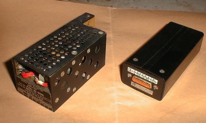
CJ
22nd Dec 2010, 22:00
permalink Post: 954
superstab
CliveL -
Many thanks for the superstab explanation -it makes more sense as a manoeuvre-driven input than as low-speed protection as the conversion course implied.
I'm trying to remember what drove the fixed nose-down elevon input at low CAS/high alpha which I alluded to earlier. Presumably it wasn't superstab but some other element of the autostab system; is NW1, Bellerophon or Brit312 able to help me out here?
Last edited by EXWOK; 23rd Dec 2010 at 08:02 .