27th Aug 2010, 19:42
permalink Post: 140
Yes we always started just the two inboard engines prior to push back and the outers when the push back was complete. This was for a number of reasons, but I do seem to remember it was not unheard of to break the tow bar shear pin on the initial push, so the less power the better
Remember that Concorde had no APU and no across the ship ducting for stating engines, therefore prior to push an air start unit was plugged into each pair of engines and the inboard engines would be started. This allowed, after push back, air from each inboard engine to be used to start it's outboard engine.
The other good reason for starting the inboards prior to push was that with no APU the cabin temp would rise quite quickly [specially in places like Bahrain in summer] and never mind the passengers
comfort, but some of M2dude and ChristiaanJ fancy electronic equipment was very temp sensitive , especially those intake control units down the rear galley. With Two engines running we could use their bleed air to at least try and hold the cabin air temp during the push back
When we first started LHR-IAD flights[ prior to thin lip///54% and other mods which improved our range] some thought was given to towing the aircraft to the taxi way near the end of the runway before starting engines so as to save fuel. I do not remember this actually ever being done though.
\
3rd Sep 2010, 19:24
permalink Post: 201
Biggles,
The Braniff crews [ I think it was 5 sets of crew] were trained for Concorde with some of crews trained in France whilst the others were trained in the UK. Flying training was done using an Air France Concorde
F-BVFA with flying being at Shannon initially but when they ran out of fuel it was moved to Montpellier. As their operation was to be subsonic they were only trained to operate the aircraft subsonically, but they were given a supersonic trans Atlantic trip as an observer.
ChristiaanJ
If I remember correctly ground effect tended to force the aircraft nose down, so requiring the pilots to pull back on the stick as if they were flaring ,but in fact what they were doing was as you say maintaining the pitch attitude constant. I have to say that in the early days the landing could be a bit of a hit or miss affair with some being perfect and some less so. The crews were originally taught to pull the power off in one stroke at about 15ft, but later they used to bleed it off and in my opinion this improved the landings greatly.
The problem with landing Concorde was when it got into ground effect if you let the nose drop you lost a lot of lift and arrived somewhat heavily. However if you pulled too hard you could raise the nose too much and suffer a big loss of speed causing a subsequent un-attractive landing, and you could also touch the tail wheel. This touch would be noticed by the ground engineer after landing as a scuff mark on the tail gear tyres. Therefore your friendly F/E on his external check prior to departure would always check the tail wheel tyres for scuff marks and if there were any you could inform the engineers at the other end of the trip that they were there prior to you taking the aircraft, and they would have to go and find another crew to blame
At touch down the pilots eye height was similar to that of a 747 pilot at touch down. Below 800ft when the aircraft had slowed down to landing speed the pitch attitude was such that the F/E could not see the runway ahead
28th Oct 2010, 06:07
permalink Post: 620
Forgive me if this has been covered before but did the Concorde have bleed air wing or fin Anti-Icing ?
What about the engines
Or was this deemed unecessary ?
What about the engines
Or was this deemed unecessary ?
28th Oct 2010, 09:19
permalink Post: 622
Quote:
| Forgive me if this has been covered before but did the Concorde have bleed air wing or fin Anti-Icing ? |
Now the leading edges of the intakes and the leading edges of various bits within the intake along with the underside of the wing in front of the the intakes were deiced by a combination of continuous and cyclic electrically heated mats.
All of this electrically heated deicing was infact extened engine deicing so as to ensure that when the ice came off it would be in small enough chunks for the engine to digest without damage. [Another system almost direct from the Bristol Britannia]
The fin nor the rest of the wing had any anti icing system
5th Dec 2010, 12:44
permalink Post: 837
why was the Olympus so suitable
Quote:
| what was it about the Olympus that made it so capable in so many guises and for so long? |
All these engines from other manufacturers have complicated systems to make them efficient:
VIGV's (Variable Inlet Guide Vanes)
VSV's (Variable Stator Vanes)
Bleed Valves
Multi Fuel Metering Valves & other valves to keep emissions under control.
The Olympus - nowt ! Two Spools and a Fuel Valve thats your lot. nothing to go wrong and being an Aeroderivative all the ancillary equipment is either bolted on underneath or away from the engine outside the enclosure.

The only thing I had trouble with was the burner bolts shearing off, 1/4"BSF, if never touched in a good few years !

Was it all still BSF on the 593? That was a Bristols thing - true RR designs are UNC (well Avons are anyway)
oh ! I forgot about the Hot Shot; when I was ground running installed RB199's there was no jump in TBT/T7, you couldn't sense it fire either, the only feel was either the Reheat lighting off with a big roar or the engine going quiet as the Nozzle opened up until the MECU noticed it hadn't lit and closed it again sharpish.
Good eh
Regards
H
 wie
wie
Last edited by howiehowie93; 5th Dec 2010 at 13:25 . Reason: Hot Shot paragraph added. Also SPELLING !! see me after school.
19th Dec 2010, 19:01
permalink Post: 892
I haven't worked out how to reply to postings and quote the relevant remarks yet - cut and paste doesn't seem to work, sorry.
Anyway, after that 1980 engine fire incident we did find a couple of small holes in the centrewall and as a result we fitted some ceramic coated steel plates in the vulnerable areas.
But as stated, the fire precautions built in did a good job. In this connection though it is worth saying that the cooling air passing over the engine comes from the ramp bleed in the intake and that it is controlled by 'secondary air doors' in the corners left between the circular engine and the square nacelle. These are there to stop air flowing back from the engine bay into the intake during takeoff and are opened once the pressure diferential between intake and engine bay is favourable. Part of the fire drill was to close these doors so the engine fire was deprived of oxygen, which helps a lot
CliveL
21st Dec 2010, 09:17
permalink Post: 907
CliveL
First of all a hearty welcome from myself also to the thread, speaking as a fellow old Filtonian/Fairfordian. (I'm sure I must have bumped into you during my years at BAC Clive).
It is thanks to the tremendous skill and dedication of 'designer chaps', such as yourself and ChristiaanJ, that Concorde became this breathtakingly amazing aeroplane that she was. I can't wait to read some more of your informative posts; you obviously have one hell of a story to tell, and can obviously teach us all (especially me) a thing or three.
It was thanks to this superb system for sealing off the engine bay (as well as actuating closed the nacelle ground running flap) when the ESDH (fire handle) was pulled, that generally limited the damage caused by the engine bay fire you mentioned on G-BOAF in 1980 to the affected engine only. (Save as you say, those small holes in the centre wall). Also worth mentioning is the fact that extinguisher pressure would also trip a 'fire flap', that would isolate the ram airflow into the air conditioning heat exchangers, that were mounted directly above the engines.. In the case of the aforementioned incident, this was just as well, as both heat exchangers were seriously damaged by the fire, and another potential source of oxygen was fortunately removed. Yet another truly brilliant piece of design.
Best Regards
Dude
First of all a hearty welcome from myself also to the thread, speaking as a fellow old Filtonian/Fairfordian. (I'm sure I must have bumped into you during my years at BAC Clive).
It is thanks to the tremendous skill and dedication of 'designer chaps', such as yourself and ChristiaanJ, that Concorde became this breathtakingly amazing aeroplane that she was. I can't wait to read some more of your informative posts; you obviously have one hell of a story to tell, and can obviously teach us all (especially me) a thing or three.
Quote:
|
Anyway, after that 1980 engine fire incident we did find a couple of small holes in the centrewall and as a result we fitted some ceramic coated steel plates in the vulnerable areas.
But as stated, the fire precautions built in did a good job. In this connection though it is worth saying that the cooling air passing over the engine comes from the ramp bleed in the intake and that it is controlled by 'secondary air doors' in the corners left between the circular engine and the square nacelle. These are there to stop air flowing back from the engine bay into the intake during takeoff and are opened once the pressure diferential between intake and engine bay is favourable. Part of the fire drill was to close these doors so the engine fire was deprived of oxygen, which helps a lot |
Best Regards
Dude
Last edited by M2dude; 21st Dec 2010 at 09:37 .
13th Jan 2011, 11:10
permalink Post: 1083
Quote:
|
Originally Posted by
M2Dude
Really an answer for CliveL, but I'll have a go. The short answer to your question is 'oh yeah, big time'. Total temperature varies with the SQUARE of Mach number and static temperature. Depending on the height of the tropopause itself as well as other local factors, there can be little or no significant variation of static temperature between FL600 and FL700. The 400\xb0K (127\xb0C) Tmo limit was imposed for reasons of thermal fatigue life, and equates to Mach 2.0 at ISA +5. (Most of the time the lower than ISA +5 static air temperatures kept us well away from Tmo). In a nutshell, flying higher in the stratosphere gains you very little as far as temperature goes. (Even taking into account the very small positive lapse above FL 650 in a standard atmosphere). As far as the MAX SPEED bit goes, Concorde was as we know flown to a maximum of Mach 2.23 on A/C 101, but with the production intake and 'final' AICU N1 limiter law, the maximum achievable Mach number in level flight is about Mach 2.13. (Also theoretically, somewhere between Mach 2.2 and 2.3, the front few intake shocks would be 'pushed' back beyond the lower lip, the resulting flow distortion causing multiple severe and surges).
On C of A renewal test flights (what I always called the 'fun flights') we DID used to do a 'flat' acceleration to Mach 2.1 quite regularly, as part of the test regime, and the aircraft used to take things in her stride beautifully. (And the intakes themselves were totally un-phased by the zero G pushover that we did at FL630) |
As usual Dude you beat me to it! I really must give up having another life

As Dude says, the 'cruise' condition was set by the aircraft specification for transatlantic range on an 85% (ISA +5) day and the chosen mach Number was 2.0 (of which more anon). This gives a Total Temperature of 400.1 deg K. [Dude, I know your pipe-smoking thermodynamicist and he was having you on - he is quite capable of memorising the square/square root of 407.6 or whatever!]
To give margins for sudden changes in ambient temperature (we had to cater for a 21 deg change in one mile) the Mmo was set at 2.04 which matches 400 degK at ISA +1. In theory then we could have flown faster than our chose Mmo at anything colder than this, but there are two limits:
1) The object is not to fly as fast as you can but to fly with minimum miles/gallon. If you have a nice cold day and enough thrust to go either faster or higher which do you choose? For best specific range you go higher every time.
2) The thing that everyone forgets is that civil aircraft have to have margins around their authorised envelope. In Concorde's case these were set principally by the intake limits and engine surge.
Dude also says quite correctly that 101 flew to 2.23M but the production aircraft was limited to 2.13M. Now you may not believe this, but 101 could fly faster than the production aircraft because she (101) leaked like a sieve!.
I doubt I will get away with that without some explanation

Once you get past a certain Mach Number the airflow into the intake is fixed. The performance (intake pressure recovery and engine face flow distortion) then depends on how this air is shared between the engine and the throat 'bleed'. This bleed was ducted over the engine as cooling air and then exhausted (in principle) throught the annulus formed between the expanding primary jet and the fixed walls of the con-di nozzle. But if you took, or tried to take, more bleed air the intake pressure recovery went up and the primary jet pipe pressure went up with it. This meant that the primary jet expanded more and squeezed the available annulus area which restricted the amount of bleed air one could take.
Obviously if there are alternative exit paths between intake and final nozzle then you can take more bleed air off and the engine face flow distortions will benefit along with the surge margin. 101 was fairly 'leaky' in this respect, particularly around the thrust reverser buckets on the original nozzle design. This meant that 101's intake distortions were lower than the production aircraft so she could fly faster without surge - at least with the first attempt at intake control 'laws'. We managed to tweak most of the margin back eventually. Engine bay leaks were good for surge margin but VERY bad news for m.p.g.!
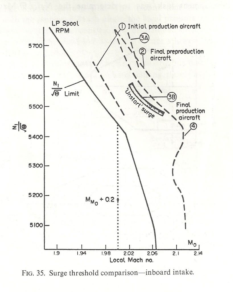
Here are a couple of diagrams to show what I mean. the first shows the surge lines for the various aircraft variants and also the N1 limiter Dude was talking about. NB: the X-axis is LOCAL Mach Number not freestream. The difference comes from the compression of the underwing flow by the bit of the wing ahead of the intake. Mmo + 0.2 is shown
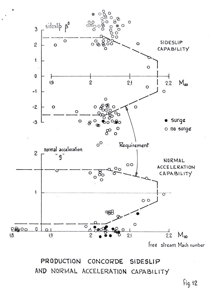
 ">The next shows the surge free boundaries in sideslip and normal acceleration. You can see the zero 'g' capability Dude was enthusing over.
 ">
">
As for 'high speed stall', I don't think we ever contemplated trying it! Our requirements in 'g' capability were defined and that was it. Besides, the aircraft would fly like the proverbial stone-built outbuilding at those sorts of conditions so I don't think one would have been able to get anywhere near a stall in the conventional sense. Stall as commonly defined for subsonics (deterrent buffet) might have been another matter, but I don't remember anything.
Cheers
Last edited by CliveL; 13th Jan 2011 at 11:17 . Reason: additional explanation
12th Mar 2011, 21:49
permalink Post: 1239
The engine starting sequence was also in airline operation 3-4-2-1. At the gate the altered sequence was 3-2 prior the pushback and 4-1 after due to safety reasons for ground crew and for noise restrictions at some airport stands.
Brit312 explained in post #140:
I must admit that I am no expert (not yet
), but it seems both sequences follow the logic to feed the blue hydraulic by engine#3 first, then one of the two yellow systems (2 or 4) and the green hydraulic (engines 1&2) which supplies power to some more services than the blue (droop nose and visor, landing gear, main wheel brakes with anti-skid and nosewheel steering).
Well, I hope, this was not a stupid answer before I took a chance for a nonstupid question - but I am so exited about this thread and just want a little bit to give back!
Thanks for the probably best thing ever I have found in the internet. Thank you M2dude, Brit312, ChristiaanJ, Exwok, Bellerophon, Landlady et al.!
Brit312 explained in post #140:
Quote:
|
Yes we always started just the two inboard engines prior to push back and the outers when the push back was complete. This was for a number of reasons, but I do seem to remember it was not unheard of to break the tow bar shear pin on the initial push, so the less power the better
Remember that Concorde had no APU and no across the ship ducting for stating engines, therefore prior to push an air start unit was plugged into each pair of engines and the inboard engines would be started. This allowed, after push back, air from each inboard engine to be used to start it's outboard engine. The other good reason for starting the inboards prior to push was that with no APU the cabin temp would rise quite quickly [specially in places like Bahrain in summer] and never mind the passengers comfort, but some of M2dude and ChristiaanJ fancy electronic equipment was very temp sensitive , especially those intake control units down the rear galley. With Two engines running we could use their bleed air to at least try and hold the cabin air temp during the push back |
), but it seems both sequences follow the logic to feed the blue hydraulic by engine#3 first, then one of the two yellow systems (2 or 4) and the green hydraulic (engines 1&2) which supplies power to some more services than the blue (droop nose and visor, landing gear, main wheel brakes with anti-skid and nosewheel steering).
Well, I hope, this was not a stupid answer before I took a chance for a nonstupid question
- but I am so exited about this thread and just want a little bit to give back!
Thanks for the probably best thing ever I have found in the internet. Thank you M2dude, Brit312, ChristiaanJ, Exwok, Bellerophon, Landlady et al.!
5th Apr 2011, 18:09
permalink Post: 1258
Dude, those are very nice illustrations, but I would make a small correction to the lower picture - the bleed flow is shown as entering the void at the front of the slot between the front and rear ramps whereas in reality it goes (sorry went :-( ) in at the rear behind the terminal shock. The increase in pressure behind that shock was the 'drive' for bleed flow.
Regards
CliveL
Regards
CliveL
5th Apr 2011, 19:09
permalink Post: 1260
CliveL
Quote:
| Dude, those are very nice illustrations, but I would make a small correction to the lower picture - the bleed flow is shown as entering the void at the front of the slot between the front and rear ramps whereas in reality it goes (sorry went :-( ) in at the rear behind the terminal shock. The increase in pressure behind that shock was the 'drive' for bleed flow. |
(As always you are of course 100% on the bal. And what do aerodynamisits know about aerodynamics anyway
 ).
).
Best regards
Dude
27th Oct 2012, 09:40
permalink Post: 1689
How about this:
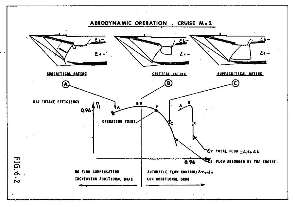
In normal operation (centre picture), the flow in the upper half of the intake was supersonic with a normal shock as required to decelerate to subsonic conditions. In the lower half the flow was decelerated to just sonic by the cowl shock. If the engine demand increased the region of supersonic flow got bigger until it nearly filled the intake (right hand picture).
The small reversed "D" zone just below the bleed slot is the supersonic region. The bleed flow entered the bleed aft of the normal shock.
Last edited by CliveL; 27th Oct 2012 at 09:44 .
28th Oct 2012, 08:16
permalink Post: 1691
@ peter kent
As you say, a complex subject!
Maybe the missing link is that a plane shock is not the only way to decelerate through Mach 1.0. If the nose of a body is blunt, or if the angle you are trying to turn the flow through is too big then the shock wave becomes detached from the leading edge of the body. The bit of the shock on the 'cusp' is then actually a very strong plane (normal) shock and the flow immediately behind that part is subsonic. In the case of a sharp surface with a large tuning angle this subsonic flow allows air to escape from the high pressure side of the surface to the low pressure side. This would be the case for example if the flow onto the leading edge of an intake hit it at too big an angle.
Supersonic intakes come in two basic guises - external compression and internal compression. The ramjet intakes you have been reading about are the latter type in which all the deceleration/compression takes place inside the intake. In these designs the final compression is through a normal shock situated at the minimum area 'throat' of the intake where the flow is close to Mach 1.0. This flow is delicately balanced and if some engine disturbance causes the shock to move into the converging supersonic bit of the intake the whole shock system can be expelled giving all sorts of problems (inlet unstart). Generally they are used for high Mach numbers where their higher theoretical efficiency and low external/spillage drag count for more than the additional control system complexity and performance requirements.
In external compression intakes (a simple pitot intake would be an extreme example), all the compression is done by a system of shock waves that sit outside the intake. These intakes are less efficient than internal compression intakes and they also spill a lot of air which produces external drag. Usually restricted to low supersonic Mach numbers.
Concorde's intake was a "mixed compression" design which had some features of each type. At low engine mass flow demands the flow coming on to the cowl lip could be at too great an angle to maintain attached shock waves so it behaved a bit like that described earlier. You can see this most clearly in the left hand picture where the lower efficiency and higher spillage can be seen in the graph of efficiency against intake capture (epsilon). In this state the intake behaved more like an external compression type and there was no appreciable final normal shock.
At high engine demand the angle of flow hitting the cowl was such that the shock waves remained attached and the intake functioned more like an internal compression design. Again you can see this in the right hand picture which shows most of the intake throat covered by a normal shock and in the graph where total intake flow (engine plus bleed) is constant.
On condition there was a bit of each, but since it was designed to minimise spillage you cannot see the detachment of the cowl lip shock at the scale of the diagram.
Hope this is helpful rather than additionally confusing!
PS: Looking at the centre picture again, it occurs to me that the curved shock running from the lip back and up to the reversed "D" would actually be normal to the approaching local flow which was being turned by the ramps and the isentropic compression. This would be the shock you are looking for to decelerate the flow to subsonic conditions. In other words the intake was functioning as an external compression design over this part.
Last edited by CliveL; 28th Oct 2012 at 08:28 .
5th Apr 2015, 08:55
permalink Post: 1851
@EXWOK
There was a certification requirement for descent time from FL600 down to FL100 if I recall correctly. Can't remember the value though. In flight reverse was developed to trim some fraction of a minute off the time to get inside the requirement
@ a_q
Not sure what you mean by a "leaky" intake. At about 2.2M the first shock would hit the intake lower lip and from that point on the total intake mass flow was frozen. Increased engine mass flow could only be obtained by reducing bleed flow and that gave higher engine face flow distortions driving the engine towards surge and lower intake recovery. So engine mass flow was effectively fixed also.
Then the amount of "dry" fuel which could be added was limited because the higher Mach number increased the engine entry temperature but the maximum turbine entry temperature was fixed.
You could add thrust by using reheat, but you would not get as much as you would like because the final nozzle, being designed for 2.0M would be too small for optimum efficiency at higher Mach numbers.
Overall, IIRC we got to 2.23M in flight test. If you pushed me I would say it might be possible with reheat etc to get to 2.25 or 2.26M, but it would be a blind guess!
16th Jul 2016, 17:01
permalink Post: 1944
According to this, 5500-6000 feet/1700 meters
Heritage Concorde
IIRC from one of the previous posts here, the strong differential required also defined the normal descent/deceleration timing and distance.
Power could only be reduced to 94% (N1 or N2, I forget which) or there would not be enough "bleed" air available to maintain the cabin altitude at TOD.
(although I could have misinterpreted that - it may have had more to do with maintaining the oblique inlet shocks, or hydraulics, or some such.)