19th Aug 2010, 04:10
permalink Post: 24
Damn, guess I am really that stupid.
 (Let's just keep that between you, Christiaan and myself ).
M2, the figures you give are incredible (I like stats) so I shall ask for more. Anytime you get tired of answering please just say enough .
How much fuel was used in the taxi. T/O roll. To TOC. Usage in cruise. From TOD?
How long did it take to get to TOC and was it done in one hit or were there stages when fuel burn allowed the climb to resume? What was the ground distance covered to get to TOC? How far out was TOD and what was ROD during the approach?
The amusing trim piece I found quite funny. That requirement must have been designed by several different Government committees; net result, nothing changes.
Had a question on the nose. You mentioned somewhere about a decompression when the nose was lowered to the 5\xb0 stage. This indicates that the nose had more than the Up and Down positions that I always thought. Were there multiple nose positions and when would they have been used. (Obviously nose full down was for T/O and Landing)
Last one for this post. What was the CoG range? I remember when I started flying and finally twigged to what it was all about that the PA28 had something like a 5" from the forward to aft limit and was massively surprised by the small "balance point". Trim tanks on 1 aeroplane I flew would have been most welcome.
I know I have asked a lot so please answer at your convenience.
Many thanks.
(Let's just keep that between you, Christiaan and myself ).
M2, the figures you give are incredible (I like stats) so I shall ask for more. Anytime you get tired of answering please just say enough .
How much fuel was used in the taxi. T/O roll. To TOC. Usage in cruise. From TOD?
How long did it take to get to TOC and was it done in one hit or were there stages when fuel burn allowed the climb to resume? What was the ground distance covered to get to TOC? How far out was TOD and what was ROD during the approach?
The amusing trim piece I found quite funny. That requirement must have been designed by several different Government committees; net result, nothing changes.
Had a question on the nose. You mentioned somewhere about a decompression when the nose was lowered to the 5\xb0 stage. This indicates that the nose had more than the Up and Down positions that I always thought. Were there multiple nose positions and when would they have been used. (Obviously nose full down was for T/O and Landing)
Last one for this post. What was the CoG range? I remember when I started flying and finally twigged to what it was all about that the PA28 had something like a 5" from the forward to aft limit and was massively surprised by the small "balance point". Trim tanks on 1 aeroplane I flew would have been most welcome.
I know I have asked a lot so please answer at your convenience.
Many thanks.
21st Aug 2010, 10:47
permalink Post: 44
Biggles78
Sorry Biggles78, I'd forgotten to answer your CofG query, so here we go: CofG was a really critical parameter on Concorde, being a delta, with no tailplane made it more so at take off speeds, and as we've previously said, was how we trimmed the aircraft for supersonic flight. CG was expressed as a percentage of the aerodynamic chord line. To get indication of CG you needed to know the mass of fuel in each tank; easy, from the FQI system. You needed to know the moment arm of each tank, (fixed of course). You then needed the zero fuel weight (ZFW) and zero fuel CG (ZFCG); these were manually input into the CG computers by the F/E, from load control data. The final parameter you needed was total fuel weight, again easy from the FQI system.
The 'normal' T/O CG was 53.5%, but in order to increase fuel weight (and hence range) an extra 'bump' was enabled to allow a max T/O CG of 54%. (CG was indicated on a linear gauge, with forward and aft limit 'bugs' either side of the needle. These bugs would move as a function of Mach and at the lower end of the speed range, A/C weight also). As the A/C accelerated, the limit bugs would move rearwards (with of course the rearward shifting centre of pressure) and so the fuel would be moved from the two front trim tanks 9 & 10 to the rear tank. 11. Once tank 11 reached it's preset limit (around 10 tonnes), the remainder of the 'front' fuel would automatically over-spill into tanks 5 & 7. (Once the fuel panel was set up, the whole process was controlled with a single switch). At Mach 2, the CG would be around 59%, the whole rearwards shift being in the order of 6'. As we said before, the 'final' CG could be tweaked to give us a 1/2 degree down elevon, for minimum drag.
I really hope this helps Biggles78.
Guys, back to the Airbus thing; My friend ChristiaanJ gave some really accurate insights, (he always does) but there is another legacy that carries on the this day; some of the audio warning tones were COPIED from Concorde into Airbus. (For example, the A/P disconnect audio is identical). I think this is great, and gives 'our' aircraft a lasting everyday legacy.
As far as the fly by wire goes, Concorde had a relatively simple analog system, with little or no envelope protection (Except at extreme angles if attack). As has been previously poted before, production series test aircraft 201, F-WTSB, pioneered the use of a sidestick within a new digital fly by wire Controlled Conviguration Vehicle sytem, with envelope protection and attitude rate feedback. (This evolved into the superb system known and loved by the Airbus community). It is a really bizaar twist of fate that the Concorde FBW system has more mechanical similarities to the system used in the B777 than Airbus. (Mechanically similar at the front end, with an electric backdrive system moving the column in A/P mode; Concorde being backdriven by a hydraulic relay jack).
As a final piece of irony; the Primary Flight Control Computers on the B777 are designed and built by GEC Marconi Avionics in Rochester Kent, now BAe Systems. This is the same plant where Elliot (becoming Marconi and finally GEC Marconi Avionics) developed and built the UK half of the AFCS computers. Isn't this aviation world strange?
Galaxy Flyer
Your inputs here are great, and I'm sure appreciated by all. (I assume from your name that you were a C5A pilot. While I was in the RAF on C-130's, our Lockheed rep' used to supply us all with company magazines, that were full of stuff on this new (it was then) giant of the sky. I fell in love with it there and then).
Anyway, back to Conc': The decel' positions were carefully worked out and adhered to; the aim was to be subsonic to within (I think) 50 nm of the east coast. I'll wait for one of my Concorde pilot friends to confirm that here, but i think I'm correct. I do have a fond memory of one flight out of JFK; we were temporarily 'held' by Boston ATC to Mach 1.6 (and at around FL440) because of an Air France Concorde heading for JFK. We saw this guy above us, at around FL580 on a near reciprical , doing Mach 2, screaming straight over the top of us. We were excited by this amazing spectacle, and so were the AF crew over the VHF ('you never boomed us, did we boom you?'). But the most excited person of all was this guy in Boston ATC. ('I've never seen anything like it guys, your two blips whistled over each other on my my screen like crazy').
Stliton
As far as the F/D noise levels were concerned, once the nose and visor were raised, it was as if someone had switched off the noise
. The main source of noise up there was just the equipment cooling, and that was not bad either. It was, in my view, little noisier up than most subsonics. (But not the 744, where you are so far away from all the racket
 ).
).
Ozgrade3
You're making us blush here; thanks for your comments, I think we are just trying to share some of our experiences (and 'bit's we've picked up over the years).
From my perspective, I did write some stuff used by our pilots, AF even got a copy or two I think.
Quote:
|
Last one for this post. What was the CoG range? I remember when I started flying and finally twigged to what it was all about that the PA28 had something like a 5" from the forward to aft limit and was massively surprised by the small "balance point". Trim tanks on 1 aeroplane I flew would have been most welcome.
|
The 'normal' T/O CG was 53.5%, but in order to increase fuel weight (and hence range) an extra 'bump' was enabled to allow a max T/O CG of 54%. (CG was indicated on a linear gauge, with forward and aft limit 'bugs' either side of the needle. These bugs would move as a function of Mach and at the lower end of the speed range, A/C weight also). As the A/C accelerated, the limit bugs would move rearwards (with of course the rearward shifting centre of pressure) and so the fuel would be moved from the two front trim tanks 9 & 10 to the rear tank. 11. Once tank 11 reached it's preset limit (around 10 tonnes), the remainder of the 'front' fuel would automatically over-spill into tanks 5 & 7. (Once the fuel panel was set up, the whole process was controlled with a single switch). At Mach 2, the CG would be around 59%, the whole rearwards shift being in the order of 6'. As we said before, the 'final' CG could be tweaked to give us a 1/2 degree down elevon, for minimum drag.
I really hope this helps Biggles78.
Guys, back to the Airbus thing; My friend ChristiaanJ gave some really accurate insights, (he always does) but there is another legacy that carries on the this day; some of the audio warning tones were COPIED from Concorde into Airbus. (For example, the A/P disconnect audio is identical). I think this is great, and gives 'our' aircraft a lasting everyday legacy.
As far as the fly by wire goes, Concorde had a relatively simple analog system, with little or no envelope protection (Except at extreme angles if attack). As has been previously poted before, production series test aircraft 201, F-WTSB, pioneered the use of a sidestick within a new digital fly by wire Controlled Conviguration Vehicle sytem, with envelope protection and attitude rate feedback. (This evolved into the superb system known and loved by the Airbus community). It is a really bizaar twist of fate that the Concorde FBW system has more mechanical similarities to the system used in the B777 than Airbus. (Mechanically similar at the front end, with an electric backdrive system moving the column in A/P mode; Concorde being backdriven by a hydraulic relay jack).
As a final piece of irony; the Primary Flight Control Computers on the B777 are designed and built by GEC Marconi Avionics in Rochester Kent, now BAe Systems. This is the same plant where Elliot (becoming Marconi and finally GEC Marconi Avionics) developed and built the UK half of the AFCS computers. Isn't this aviation world strange?
Galaxy Flyer
Your inputs here are great, and I'm sure appreciated by all. (I assume from your name that you were a C5A pilot. While I was in the RAF on C-130's, our Lockheed rep' used to supply us all with company magazines, that were full of stuff on this new (it was then) giant of the sky. I fell in love with it there and then).
Anyway, back to Conc': The decel' positions were carefully worked out and adhered to; the aim was to be subsonic to within (I think) 50 nm of the east coast. I'll wait for one of my Concorde pilot friends to confirm that here, but i think I'm correct. I do have a fond memory of one flight out of JFK; we were temporarily 'held' by Boston ATC to Mach 1.6 (and at around FL440) because of an Air France Concorde heading for JFK. We saw this guy above us, at around FL580 on a near reciprical , doing Mach 2, screaming straight over the top of us. We were excited by this amazing spectacle, and so were the AF crew over the VHF ('you never boomed us, did we boom you?'). But the most excited person of all was this guy in Boston ATC. ('I've never seen anything like it guys, your two blips whistled over each other on my my screen like crazy').
Stliton
As far as the F/D noise levels were concerned, once the nose and visor were raised, it was as if someone had switched off the noise
. The main source of noise up there was just the equipment cooling, and that was not bad either. It was, in my view, little noisier up than most subsonics. (But not the 744, where you are so far away from all the racket
).
Ozgrade3
You're making us blush here; thanks for your comments, I think we are just trying to share some of our experiences (and 'bit's we've picked up over the years).
From my perspective, I did write some stuff used by our pilots, AF even got a copy or two I think.
Last edited by M2dude; 21st Aug 2010 at 13:01 . Reason: couple of corrections; this guy can't spell
21st Aug 2010, 15:57
permalink Post: 47
First, I must apologise to Stilton for hi-jacking his thread. I had inadvertantly asked a question in the wrong thread and have only just realised it, so sorry Stilton. The good part of this is all this delicious Concorde info that were are privileged to be receiving from M2dude and ChristiaanJ is all in the one thread. Unless anyone has any objections maybe the Forum Moderator could merged the other 2 threads into this one.
Thank you for the CoG answer. 6 feet sounds like an awful lot but then I am only able to compare it to the littlies that I fly. The ability to use the trim tanks to only have to use a \xbd\xb0 of elevon must have made a substantial impact on performance and the resulting reduced fuel consumption. To think it was all computer controlled at the time when the PC didn't even exist.
M2, you have said that the fuel system was a work of elegance and the above desciption give me a small insight into this. I know that I am just going to have to find books written about this lady to find out more. I have been lazy when asking about item that I could Google but there was a method behind my laziness. When you and Christiaan share your knowledge there is always a personal anecdote or insight that will never be found in any books that I may be able to find. Gentlemen, for this THANKS seem so insufficient.
The TOC=TOD had me thinking and I believe insomnia may have assisted with some understanding (otherwise the stupid sign for me comes out again ). Gee I hope I have this even partly right. I assume that when accelerating to Mach 2, that it was done while climbing. I was initially stuck with the compression factor of Mach 1 and without thinking the same would happen at Mach 2 (A C Kermode was the hardest book I have read that I didn't understand
 ). Therefore with that in mind I was stuck trying to figure TOC=TOD. Am I right or even slightly so in thinking that cruise climb and cruise descent
was
the flight and there was minimal actual level cruise in the "pond" crossing?
). Therefore with that in mind I was stuck trying to figure TOC=TOD. Am I right or even slightly so in thinking that cruise climb and cruise descent
was
the flight and there was minimal actual level cruise in the "pond" crossing?
I had also forgotten to take into account the speed factor, DUH!! Subsonic climbs, what 35 - 45 mins to FL4xx and then it is in level cruise for the next 6 hours before TOD. The lady took what, about 3.5 hours, and the extra 20,000 feet it had to climb and descend ate up or into any level cruise it had (or didn't have). Am I on the right track or am I making an ass out of me and me.
I was in the jump seat of a B767 on a trans Tasman crossing, CAVOK, when about 2,000 feet lower a dot followed by a straight white cloud approached and passed by. I found that impressive so the 2 supersonics passing at the speed of an SR71 must have been spectacular. Shame radar track isn't available on You Tube. Oh yes, did they boom you?
As you have said, fuel flow was reduced the higher you got. I think it was 5T per powerplant at FL500 down to 4.1T at FL600. Was there any figures for higher the Levels? I am curious to see how much less fuel would have been used at the higher FLs considering it was reduced by 900Kg/hr for just 10K feet. Very interesting what you said about when the temps were ISA+. I would never have thought such a small temperature change could have effected such a signifigant performance result. It also sounds odd, as you said, the faster you go the less fuel you use.
Last greedy question for this post. How much of the descent was carried out while supersonic and how did this affect the fuel flow?
Thank you for the CoG answer. 6 feet sounds like an awful lot but then I am only able to compare it to the littlies that I fly. The ability to use the trim tanks to only have to use a \xbd\xb0 of elevon must have made a substantial impact on performance and the resulting reduced fuel consumption. To think it was all computer controlled at the time when the PC didn't even exist.
M2, you have said that the fuel system was a work of elegance and the above desciption give me a small insight into this. I know that I am just going to have to find books written about this lady to find out more. I have been lazy when asking about item that I could Google but there was a method behind my laziness. When you and Christiaan share your knowledge there is always a personal anecdote or insight that will never be found in any books that I may be able to find. Gentlemen, for this THANKS seem so insufficient.
The TOC=TOD had me thinking and I believe insomnia may have assisted with some understanding (otherwise the stupid sign for me comes out again
). Gee I hope I have this even partly right. I assume that when accelerating to Mach 2, that it was done while climbing. I was initially stuck with the compression factor of Mach 1 and without thinking the same would happen at Mach 2 (A C Kermode was the hardest book I have read that I didn't understand
). Therefore with that in mind I was stuck trying to figure TOC=TOD. Am I right or even slightly so in thinking that cruise climb and cruise descent
was
the flight and there was minimal actual level cruise in the "pond" crossing?
I had also forgotten to take into account the speed factor, DUH!! Subsonic climbs, what 35 - 45 mins to FL4xx and then it is in level cruise for the next 6 hours before TOD. The lady took what, about 3.5 hours, and the extra 20,000 feet it had to climb and descend ate up or into any level cruise it had (or didn't have). Am I on the right track or am I making an ass out of me and me.
I was in the jump seat of a B767 on a trans Tasman crossing, CAVOK, when about 2,000 feet lower a dot followed by a straight white cloud approached and passed by. I found that impressive so the 2 supersonics passing at the speed of an SR71 must have been spectacular. Shame radar track isn't available on You Tube. Oh yes, did they boom you?
As you have said, fuel flow was reduced the higher you got. I think it was 5T per powerplant at FL500 down to 4.1T at FL600. Was there any figures for higher the Levels? I am curious to see how much less fuel would have been used at the higher FLs considering it was reduced by 900Kg/hr for just 10K feet. Very interesting what you said about when the temps were ISA+. I would never have thought such a small temperature change could have effected such a signifigant performance result. It also sounds odd, as you said, the faster you go the less fuel you use.
Last greedy question for this post. How much of the descent was carried out while supersonic and how did this affect the fuel flow?
21st Aug 2010, 22:04
permalink Post: 55
Biggles78,
Re your questions about the CofG, this diagram should help you to visualise the CofG "corridor".
It's the one for G-AXDN (01) but the production one is closely similar.
To make some more sense of this.... all those percentages quoted are in terms of the "wing root reference chord".
Mentally cut the wing off the fuselage and measure the length of the cut (including the elevons)..
That's the "root reference chord", and it's 27,76 m.
To give you another reference point: the main gear attachment point is located at 57% ""root reference chord".
So any CofG beyond 57% on the ground, and you have yourself a tailsitter (it's happened)..
22nd Aug 2010, 02:02
permalink Post: 57
ChristiaanJ
For once my friend you're not quite correct. The Plessey PVS1580 Aircraft Integrated Data System, fitted to all BA aircraft from mid' 1977 used a microprocessor in the data entry panel. In the mid-80's, a fault interrrogation module was fitted to the Engine Control Units; this used a 4 bit Intel 4004. Otherwise (as usual
) we agree.
I've some production series CG diagrams, that I will post here when I can find out how to do it......
Quote:
| I don't think there was a single microprocessor on board Concorde until the days that they had to fit TCAS (in the '90s, IIRC). |
) we agree.
I've some production series CG diagrams, that I will post here when I can find out how to do it......
22nd Aug 2010, 13:18
permalink Post: 66
Biggles78
...The altitude flown was due to temperature and weight of the areoplane. This is true of all aeroplanes...
Sadly, it isn’t, as subsonic aircraft are allocated a specific cruising flight level and often - for example on the North Atlantic Track system - a specific cruising Mach number as well, and no deviation from that clearance is permitted without specific permission from ATC. Obviously everyone flight plans at the most economic heights and speeds for their aircraft type, but in busy airspace not everyone gets what they want!
Think of your flight plan as being Angelina Jolie, and your ATC clearance as being your wife. Your flight plan is what you’d really like to have, but your ATC clearance is what you’re going to have to live with!
... altitude flown was due to temperature and weight of the areoplane...this was more true of Concorde?...
Subsonic aircraft could equally benefit from using cruise-climb techniques (early long range aircraft crews knew all about cruise-climb techniques and used them when able) but with the large number of subsonic aircraft now using the world’s airways it is impractical for ATC to allow them to drift up and down at will, and so they are assigned specific cruising altitudes.
Few other aircraft got up to Concorde’s cruising levels, and so ATC were able to issue much more flexible clearances to her.
A typical Concorde ATC clearance would have allowed her to accelerate to M2.00 whilst operating within a "block" of altitude, rather than at a specific flight level. Typically this block clearance would have been to operate anywhere between FL450 up to FL600 without restriction.
So, unlike subsonic aircraft assigned a fixed cruising altitude such as FL350, Concorde could, and did, drift up or down, and was thus able to remain at the optimum altitude for the prevailing conditions throughout most of the flight.
... I remember reading the BA Concorde flew with 2 Captain Pilots (and of course the most important Flight Engineer)...
Concorde operated, as did all 3 crew aircraft in BA, with a standard crew of a Captain, F/O and F/E.
A small number of trips had two Captains on board (or two F/Es for that matter) when training or checking was going on, or an extra crew member was carried for PR purposes, but otherwise, the vast majority of occasions, just the standard crew was on board. Everyone preferred it that way, especially the F/O and F/E!
... The subsonics have issues with Coffin Corner (I think I read that one Airbus model had somehting like 7kts between the high and low end of the envelope when up high); did Concorde have this "problem"?...
Have a look at this picture of G-BOAE, cruising at her maximum certificated altitude of FL600, en-route to Barbados on 16 August 2003:
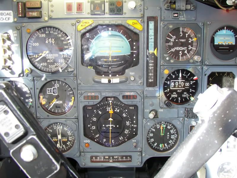
The available IAS speed range is shown on the ASI, and lies between the yellow and black Barbers Pole, currently indicating 440kts, and the white bug set to 300kts, the VLA ( L owest A uthorised speed) at this altitude.
The available Mach speed range is shown on the Mach meter, and lies between the yellow and black Barbers Pole, currently indicating M2.05, and the yellow bug which indicates the lowest Mach number allowed for the current aircraft CG position (the AFT limit) currently showing M1.35.
So, given that at her maximum altitude she had a speed range of 140kts IAS and a Mach range of M0.7, we can see that coffin corner was not a problem!
main_dog
...I too would like to ask what her idle thrust glide ratio was...
By my calculations, the figures quoted for a straight in approach, give an average glide ratio of around 20:1, however these were for a standard decel/descent, and on Concorde the early part of the decel/descent was not flown at idle power.
A considerable amount of power was left on initially, around 94% N2, for various reasons, and only below M1.0 were the throttles usually selected to idle.
I hadn’t noticed it until now but there does not appear to have been a chart giving glide distance at idle thrust!
However, since the speeds to be flown during the “4 Eng Flame Out” procedure were not too far from the normal decel/descent speeds, I’ll hazard a guess (and that is all it is) that the glide distance from FL600, with no thrust, would have been about 150nm, giving a glide ratio of around 15:1.
...The altitude flown was due to temperature and weight of the areoplane. This is true of all aeroplanes...
Sadly, it isn’t, as subsonic aircraft are allocated a specific cruising flight level and often - for example on the North Atlantic Track system - a specific cruising Mach number as well, and no deviation from that clearance is permitted without specific permission from ATC. Obviously everyone flight plans at the most economic heights and speeds for their aircraft type, but in busy airspace not everyone gets what they want!
Think of your flight plan as being Angelina Jolie, and your ATC clearance as being your wife. Your flight plan is what you’d really like to have, but your ATC clearance is what you’re going to have to live with!
... altitude flown was due to temperature and weight of the areoplane...this was more true of Concorde?...
Subsonic aircraft could equally benefit from using cruise-climb techniques (early long range aircraft crews knew all about cruise-climb techniques and used them when able) but with the large number of subsonic aircraft now using the world’s airways it is impractical for ATC to allow them to drift up and down at will, and so they are assigned specific cruising altitudes.
Few other aircraft got up to Concorde’s cruising levels, and so ATC were able to issue much more flexible clearances to her.
A typical Concorde ATC clearance would have allowed her to accelerate to M2.00 whilst operating within a "block" of altitude, rather than at a specific flight level. Typically this block clearance would have been to operate anywhere between FL450 up to FL600 without restriction.
So, unlike subsonic aircraft assigned a fixed cruising altitude such as FL350, Concorde could, and did, drift up or down, and was thus able to remain at the optimum altitude for the prevailing conditions throughout most of the flight.
... I remember reading the BA Concorde flew with 2 Captain Pilots (and of course the most important Flight Engineer)...
Concorde operated, as did all 3 crew aircraft in BA, with a standard crew of a Captain, F/O and F/E.
A small number of trips had two Captains on board (or two F/Es for that matter) when training or checking was going on, or an extra crew member was carried for PR purposes, but otherwise, the vast majority of occasions, just the standard crew was on board. Everyone preferred it that way, especially the F/O and F/E!
... The subsonics have issues with Coffin Corner (I think I read that one Airbus model had somehting like 7kts between the high and low end of the envelope when up high); did Concorde have this "problem"?...
Have a look at this picture of G-BOAE, cruising at her maximum certificated altitude of FL600, en-route to Barbados on 16 August 2003:
The available IAS speed range is shown on the ASI, and lies between the yellow and black Barbers Pole, currently indicating 440kts, and the white bug set to 300kts, the VLA ( L owest A uthorised speed) at this altitude.
The available Mach speed range is shown on the Mach meter, and lies between the yellow and black Barbers Pole, currently indicating M2.05, and the yellow bug which indicates the lowest Mach number allowed for the current aircraft CG position (the AFT limit) currently showing M1.35.
So, given that at her maximum altitude she had a speed range of 140kts IAS and a Mach range of M0.7, we can see that coffin corner was not a problem!
main_dog
...I too would like to ask what her idle thrust glide ratio was...
By my calculations, the figures quoted for a straight in approach, give an average glide ratio of around 20:1, however these were for a standard decel/descent, and on Concorde the early part of the decel/descent was not flown at idle power.
A considerable amount of power was left on initially, around 94% N2, for various reasons, and only below M1.0 were the throttles usually selected to idle.
I hadn’t noticed it until now but there does not appear to have been a chart giving glide distance at idle thrust!
However, since the speeds to be flown during the “4 Eng Flame Out” procedure were not too far from the normal decel/descent speeds, I’ll hazard a guess (and that is all it is) that the glide distance from FL600, with no thrust, would have been about 150nm, giving a glide ratio of around 15:1.
22nd Aug 2010, 15:47
permalink Post: 69
Quote:
|
Originally Posted by
Biggles78
...The altitude flown was due to temperature and weight of the areoplane. This is true of all aeroplanes...
|
 I will see if I can reword it to make it comprehensible.
Thank you for the Instrument Panel image that I have now added to my collection. What is the Yellow Arc on the Mach metre that starts at about M1.12?
Do you remember if you had a signifigant headwind at that stage? I notice that the G/S is 1,139kts was this fairly standard for an East-West flight? (DUH me. Just read the fastest crossing was an east-west direction. Winds must have been quite favorable) I am now guessing the displayed G/S would be fairly typical, plus or minus a bit.
The Glide Ratio, even if it is a highly educated guess, is impressive. I would not have expected it to have been about the same as a B747. How many more times is this Lady going to surprise me with her performance.
Also notice the ball is slightly off to the left even though it is still inside the lines. Was this normal or does it need a tad more rudder trim? Can't imagine it is really out of balance.
Quote:
|
Originally Posted by
Bellerophon
Everyone preferred it that way, especially the F/O and F/E!
|
ChristiaanJ thanks for the CoG diagram. That I am still getting my head around. There is a large range at the bottom and top of the speed range but fairly narrow in the mid speed range. Seems like 165T was a less complex balancing act than it was at 105T.
The center rear fuselage gear unit, what was that for? I have seen it deployed on many occasions but I can't for the life of me remember if it was during T/O or LDG however it didn't seem to be extended every time the aeroplane flew. Was this used during loading so she didn't accidently "rotate" at the ramp or to avoid a tailstrike during LDG? I can't imagine an over rotate during T/O.
And a big Thank You to Bellerophon for sharing his knowledge with this thread.
23rd Aug 2010, 08:28
permalink Post: 77
Biggles78
This is the minimum Mach number that can be flown with the existing CG. (which would be around 59%). Just as the CG indicator (not shown in this photo) gave minimum and maximum CG for a given Mach number, the Machmeter gave a reciprical indication also). You can also see that as the aircraft is not flying at Vmo any more, being at Mach 2 cruise, that the VSI pointer is now away from the orange and black Vmo bug. At our 'not so coffin corner', now that the aircraft is at maximun alllowable altitude, Vmo would naturaly coincide with Mmo; the orange and black Mmo bug being shown at Mach 2.04. This really superb photo taken by Bellerophon gives a graphic illustration of what the panels looked like at Mach 2. Note that the with the TCAS VSI Concorde retained it's original linear VSI also. (Miust have beeen the only aircraft flying with FOUR VSIs. (The originals had to be retained due to the fact that the autopilot Vert' Speed Mode error was derived from the indicator itself. As far as TCAS goes, R/As werer inhibited above FL300 (on acceleration this would coincide with the aircraft becoming supersonic, and the mfrs would not countenance the aircraft doing extreme manoeuvrs as a result of TCAS RAs at supersonic speeds).
The tail wheel was lowered for all 'normal' gear cycles (not stby lowering of free-fall). It was designed to protect the bottom the nacelles in the case of over-rotation, but in practical terms the thing was a waste of space (and weight) and a simple tail skid (used on the prototypes) would have sufficed. Any time that the tail wheel contacted the ground, it would ALWAYS collapse, damage the tailcone structure and in fact aforded no protection whatsoever. Fortunately these events were EXTREMELY few and far between. The biggest problem with the tail wheel was a major design flaw: On gear retraction the assembly would retract in sequence with the nose and main gear, and as it entered the opening in the tailcone, it would release over-centre locks that were holding the spring-loaded doors open. The doors would then firmly spring shut behind the gear assembly and finish the job. UNFORTUNATELY this was a very poor design; if for any reason one of the two doors had not gone over-centre on the previous gear lowering, it would be struck by the retracting tail wheel gear and cause structural damage to the local skin area, that would have to have a repair done. Unfortunately these events were not quite so rare, and several measures were tried to reduce the chance of this happening. Although not a safety issue, it was an issue that was a total pain. (As a matter of interest, G-BOAC had this happen on one of it's first test flights out of Fairford in 1975).
Nick Thomas
As ChristiaanJ said, the last two BA aircraft WERE lighter than the others, and would be preferred aircraft for certain charters. But that is not to say that any aircraft could not happily do ANY sector. We fortunately had no distorted airframes in the British fleet, so this was never an issue. There was very little spread, regarding fuel consumption between different engines; one of the best parts about the Olympus 593 was that it hade very little performance deterioration with time, it was an amazing piece of kit.
Time on wing for the engines was a real variable. Each engine was built up of modules, each one of these had a seperate life. In the early days of operation, time on wing was quite poor, and MANY engines would be removed on an attrition basis. One of the early failure problem was the fuel vapourisers inside the combustion chamber were failing, taking bits of turbine with it!! A Rolls Royce modification that completely changed the design of the vapouriser not only solved the problem completely, but also increased the performance of the engine. As the engine matured in service time on wing greatly improved, and in service failures became a thing of the past. A 'trend analysis' was done after each protracted supersonic flight, where engine parameters were input into a propiatry RR computer program, that was able to detect step changes in the figures, and if this were the case, more boroscope inspections were carried out. The OLY time on wing was nothing compared to the big fan engines, but the conditions that it operated under bore no comparison. Not really sure about absolute figures on this one Nick, I'll ask one of my Rolls Royce friends and see if I can find a figure.
Quote:
| What is the Yellow Arc on the Mach metre that starts at about M1.12? |
Quote:
| The center rear fuselage gear unit, what was that for? I have seen it deployed on many occasions but I can't for the life of me remember if it was during T/O or LDG however it didn't seem to be extended every time the aeroplane flew. Was this used during loading so she didn't accidently "rotate" at the ramp or to avoid a tailstrike during LDG? I can't imagine an over rotate during T/O. |
Nick Thomas
Quote:
| As regards fuel burn: was there any difference between each indvidual airframe and if so was it significant enough to be considered when calculating the trip fuel? Also did different engines also have slightly different fuel consumption? |
Quote:
| Whilst on the subject of engines, I just wondered how many were required to keep the BA Concorde fleet flying? What sort of useful life could be expected from the engines? |
Last edited by M2dude; 19th Jan 2011 at 13:42 .
24th Aug 2010, 10:21
permalink Post: 89
I'm just an interested non-pilot bystander, & hope it's OK to post here.
Thank you all for this truly fascinating information. I've a question arising from watching the ITVV DVDs:
Having two pilots obviously gives some options if one becomes ill or incapacitated, but how were things handled if the FE became unable to perform his duties? Did the FO take over, & how familiar were the pilots with the FE's duties - could either pilot do the FE's job in full, or was it limited to some subset such as required for a diversion/landing etc. I assume this kind of thing was practised in the simulator regularly?
I note (unless I've misunderstood) that there was some presetting of the load limit fuel transfer system, so that the pilots could initiate a CofG movement for descent if required.
Thanks!
24th Aug 2010, 14:10
permalink Post: 91
Hi M2Dude - keep it coming! I missed all this stuff from the early days......
Tim00 - good question, and very relevant.
It takes a lot to incapacitate a Flight Engineer - beer, cigars and scary women were no issue - they were definitely the most relaible part of the operation. (And arguably the least attractive.....)
If the unthinkable happened the First Officer would find himself on the FE's seat. We practised it less often than you might think, but thought about it a great deal. Especially the fuel system management.
Which brings me to your second point - yes, there was a preset for the 'automatic' fuel transfer system, although that wasn't the mechanism used for the pilots to 'take control' of the CG. The critical thing was to be able to get the CG forward if a rapid decel had to be made - for this reason there was an override switch above the First Officer which used various pumps and valves to txfr fwds - primarily by txfring from tank 11. It would be used in various recall checklists (supersonic 4-engine flameout and Continuous Ssurge at M>1.3 seem to register from the dim past) until the FE was able to take over the txfr system himself.
I didn't ever need it - in the surges I encountered the FE was always ready to manage the txfr before we needed the override.
Oooooooh!!!! There's a new topic for someone: Surges.
Theoretically the correct checklist to call for was the "Continuous Engine surge above M 1.3 Conditional Procedure, please". In reality the call was always much more succinct.
Monosyllabic, in fact................
I'm off to the pub, but I bet Bellerophon can speak with erudition on the operational aspects, and if M2Dude is who I suspect he is, I KNOW he'll be able to cover the technical aspects in great depth!
WOK
Last edited by EXWOK; 26th Aug 2010 at 23:50 .
25th Aug 2010, 19:39
permalink Post: 117
A great thread and it only goes to show that you can always learn even about a subject that you thought you knew quite a lot about
As M2Dude described the rearwards transfer of fuel during acceleration was meant to be an automated process but in reality there was a lot of manual input. The first requirement of the F/E was to match the rearwards movement of the C of G to that of the ever increasing Mach number. If this was proving to be no problem he would take over the transfer manually by switching off the pumps on one side of tank 9 or 10 so as to pump only to either tank 5 or 7. This was because if you transferred evenly to these tanks due to their different shape size and position the aircraft would go out of trim laterally so the F/E would pump rearward just to one tank so as to keep the C of G going aft whilst maintaining lateral trim.
Being Concorde nothing was straight forward , which meant that when Tanks 5 and 7 ran out and you started using tanks 6 and 8, their size shape and position,was exactly opposite to that of tanks 5 and 7 so it now required the F/E to pump fuel the opposite way across the ship, using various valves and pumps, so as to keep the aircraft in trim laterally.
All the time he had to maintain the trim so as to keep an elevon trim of \xbd deg down, which as fuel was burnt required him to trickle fuel forward from tank 11. On the longer trips such as those to and from BGI the fuel towards the end of cruise became quite low and to stop fuel in the collectors from dropping below 1000kgs each, fuel would be transferred from tank 11 into the collectors until the
C of G had reached it's forward limit at Mach 2.0 of 57.5 %. If then the collectors dropped to 1000kgs the aircraft had to descend to subsonic heights and speed.
Surges
Surges were not an uncommon or common event on Concorde,but when they happened as they usually affected both engines on that side the aircraft would lurch /yaw and everybody on board would know about it as \x93Her In Doors\x94 would testify to that when glasses full and otherwise ended up in her lap during the meal service when a surge occurred.
The drill required all engines to be throttled to a predetermined position and the intake and engine control switches moved to their other position. If this stopped the surge then the throttles were restored to their cruise power a pair at a time and if no surge re-occured then the aircraft would return to cruise / climb
The crews post surge action was normally to have a cup of tea and light up a cigarette.
In the early days on a flight between London and Bahrain when the aircraft was in supersonic cruise the F/E who was a mature and refined gentleman, had to go to the toilet, which was just behind the front galley, and whilst there the engines surged. He was seen running from the toilet to the flight deck with his trousers around his ankles, which was a hell of shock to his refined nature
Enough for now sorry about the length
3rd Sep 2010, 22:17
permalink Post: 210
ChristiaanJ
Yes, as Brit312 has suggested, the pitch change as Concorde entered ground effect on landing was nose down.
In simple terms (i.e. as it was explained to me ) due to the nose up approach attitude, (10\xbd\xb0 PA) the wider trailing edge of the wing entered ground effect before the much narrower leading edge of the wing, meaning more lift was now being generated at the rear of the wing than before, aft of the CG, resulting in a nose down pitch change.
As you say, she landed at (or very nearly at) her approach attitude, with ground effect responsible for killing most of the rate of descent, but, during the last fifty feet or so, in order to maintain that steady pitch attitude against the increasing nose down pitch change, a definite, progressive, rearward movement of the control column was required, a movement that felt remarkably like a \x93flare\x94 to the pilot.
The available pitch attitude range on landing was very tight. Depending on the approach speed selected, touchdown attitude typically would be 11\xb0 - 11\xbd\xb0, with a warning call of \x93Attitude\x94 from the NHP at 12\xbd\xb0 PA. On Concorde, effectively you only got one attempt at making a good landing, after that, with little room to manoeuvre (literally), you had to settle for a safe one, by making sure the wings were level, the rate of descent reasonable, and the pitch attitude within limits and just accepting whatever sort of touchdown she gave you!
The speed, pitch and tone of the F/E's voice, as he made the radio height calls, were as reliable an indication as any as to what sort of arrival was imminent!
Best Regards
Bellerophon
Yes, as Brit312 has suggested, the pitch change as Concorde entered ground effect on landing was nose down.
In simple terms (i.e. as it was explained to me
) due to the nose up approach attitude, (10\xbd\xb0 PA) the wider trailing edge of the wing entered ground effect before the much narrower leading edge of the wing, meaning more lift was now being generated at the rear of the wing than before, aft of the CG, resulting in a nose down pitch change.
As you say, she landed at (or very nearly at) her approach attitude, with ground effect responsible for killing most of the rate of descent, but, during the last fifty feet or so, in order to maintain that steady pitch attitude against the increasing nose down pitch change, a definite, progressive, rearward movement of the control column was required, a movement that felt remarkably like a \x93flare\x94 to the pilot.
The available pitch attitude range on landing was very tight. Depending on the approach speed selected, touchdown attitude typically would be 11\xb0 - 11\xbd\xb0, with a warning call of \x93Attitude\x94 from the NHP at 12\xbd\xb0 PA. On Concorde, effectively you only got one attempt at making a good landing, after that, with little room to manoeuvre (literally), you had to settle for a safe one, by making sure the wings were level, the rate of descent reasonable, and the pitch attitude within limits and just accepting whatever sort of touchdown she gave you!
The speed, pitch and tone of the F/E's voice, as he made the radio height calls, were as reliable an indication as any as to what sort of arrival was imminent!
Best Regards
Bellerophon
5th Sep 2010, 18:51
permalink Post: 219
Hi
I have yet another question! Last year I watched a programme where James May went up in a U2. He explained that at FL700 the plane was flying in "coffin corner" and that the difference in IAS between the stall and the max speed was only 10 knots. I understand that it's due to the very low air pressure at such heights. As Concorde could fly up to FL600 I wondered what this safe airspeed window was during the cruise/climb phase of flight and if this window was framed by the air pressure and/or the CofG position?
Once again thanks to everyone for such great answers and also for the background information.
Regards
Nick
6th Sep 2010, 09:17
permalink Post: 222
Coffin Corner
Nick Thomas
Just like Christiaanj I'm trying to dig up an accurate flight envelope diagram. (A lot of my Concorde 'technical library' is out on long term loan), but I would suggest that anywhere within Concorde's published flight envelope you never hit any equivilant to Coffin Corner, a la' U2. The whole issue is really one of air DENSITY, rather that pressure, where as you climb at a given Mach Number, your Indicated airspeed (IAS) falls away with altitude. (Velocity of sound being primarily tied to static air temperature). Now if you are climbing in the stratosphere, where temperature is more or less constant up to around 65,000', you can say that your TRUE Airspeed (TAS) is also constant with climb at a given Mach number. But lift and drag are functions of IAS (the equivalent airspeed that the aircraft would 'feel' at sea level) and not TAS. Because the U2 had a very low Maximum allowable Mach number (Mmo) as IAS fell away with altitude, it would get to the point where it's lowest permitted airspeed (we called this VLA) got to within a few knots of Mmo and severe aerodynamic buffering. i.e. you were screwed with nowhere to go but down .
.
In the case of Concorde, Mach 2 at FL500 was 530KTS, falling to 430KTS at FL600. Although we have less lift due to 100KTS lower IAS, the aircraft is now much lighter (this is the whole principal of cruise/climb) which keeps the universe in balance, but drag is now significantly lower too, getting us better MPG
.
On the ASI, the only limitation displayed was Vmo; however the Machmeter did display fwd and aft CG limits at a given Mach number. The ONLY time that Concorde would experience relatively low speeds at altitude was at Top of Descent. I'm a little fuzzy here how it all worked exactly (it's an age thing you know), I'm sure one of the pilots can correct me, but I seem to remember that the autothrottle was disconnected, ALTITUDE HOLD was selected on the AFCS, and the throttles slowly retarded. (If you pulled back too far you'd often get a gentle 'pop surge' from the engines, and you had also to be wary of equipment cooling airflow too). The aircraft was then allowed to gently decelerate, still at TOD altitude, until Mach 1.6, when power was tweaked to give 350KTS IAS and IAS HOLD was selected. The aircraft was now free to carry out her loooong descent to 'normal' altitudes. VLA on Concorde was not directly displayed as you never flew anywhere near it, and also every pilot knew his VLA
. (Stray into this and you'd get a 'stick' shaker warning.
I hope this blurb helps Nick
Dude
Just like Christiaanj I'm trying to dig up an accurate flight envelope diagram. (A lot of my Concorde 'technical library' is out on long term loan), but I would suggest that anywhere within Concorde's published flight envelope you never hit any equivilant to Coffin Corner, a la' U2. The whole issue is really one of air DENSITY, rather that pressure, where as you climb at a given Mach Number, your Indicated airspeed (IAS) falls away with altitude. (Velocity of sound being primarily tied to static air temperature). Now if you are climbing in the stratosphere, where temperature is more or less constant up to around 65,000', you can say that your TRUE Airspeed (TAS) is also constant with climb at a given Mach number. But lift and drag are functions of IAS (the equivalent airspeed that the aircraft would 'feel' at sea level) and not TAS. Because the U2 had a very low Maximum allowable Mach number (Mmo) as IAS fell away with altitude, it would get to the point where it's lowest permitted airspeed (we called this VLA) got to within a few knots of Mmo and severe aerodynamic buffering. i.e. you were screwed with nowhere to go but down
.
In the case of Concorde, Mach 2 at FL500 was 530KTS, falling to 430KTS at FL600. Although we have less lift due to 100KTS lower IAS, the aircraft is now much lighter (this is the whole principal of cruise/climb) which keeps the universe in balance, but drag is now significantly lower too, getting us better MPG
.
On the ASI, the only limitation displayed was Vmo; however the Machmeter did display fwd and aft CG limits at a given Mach number. The ONLY time that Concorde would experience relatively low speeds at altitude was at Top of Descent. I'm a little fuzzy here how it all worked exactly (it's an age thing you know), I'm sure one of the pilots can correct me, but I seem to remember that the autothrottle was disconnected, ALTITUDE HOLD was selected on the AFCS, and the throttles slowly retarded. (If you pulled back too far you'd often get a gentle 'pop surge' from the engines, and you had also to be wary of equipment cooling airflow too). The aircraft was then allowed to gently decelerate, still at TOD altitude, until Mach 1.6, when power was tweaked to give 350KTS IAS and IAS HOLD was selected. The aircraft was now free to carry out her loooong descent to 'normal' altitudes. VLA on Concorde was not directly displayed as you never flew anywhere near it, and also every pilot knew his VLA
. (Stray into this and you'd get a 'stick' shaker warning.
I hope this blurb helps Nick
Dude
6th Sep 2010, 14:40
permalink Post: 228
Hi all,
Re the flight envelope diagram, Bellerophon got ahead of me, and his scan is cleaner than mine!
I've got a second one, which is basically the same, but has the envelope for a CG of 55% and for a CG of 59% hatched in.
For anybody who wants the full scans to print them out in A4, use these links.
Flight envelope A4 format
light envelope w. CG limits A4 format
Apologies for the mediocre quality of the scans...
CJ
6th Sep 2010, 15:25
permalink Post: 230
Thanks Bellerophon and CJ for posting the flight envelope. With regard to the CofG of 59%, I notice that the upper part of the envelope abuts the MMO boundary.So is the Cof G of 59% the determining factor for the MMO or is it some other factor?
Regards
Nick
Regards
Nick
6th Sep 2010, 17:13
permalink Post: 233
Nick:
The top of the boundary is FL600, largely an artificial number - the airframe is good for rather higher than this, but I believe air supply and ramp scheduling could become an issue not so far above this level.
Mmo - ditto. As others have said, Mmo was originally going to be higher (M2.2) but was reduced to extend fatigue life as the aircraft design 'grew'.
The significance of the shaded 59% portion of the graph is that it shows the envelope at that CG - in this case the relevant line is the bottom of the shaded area - M1.56. This is the MINIMUM mach number that can be flown with the CG at 59% (normal for supersonic cruise). You will see it represented on the Machmeter (a few pages back) as the "AFT" bug. i.e. you can't fly slower than this without moving the CG forward.
So it can be seen that the decel must be done in concert with CG transfer - and as (mostly) always the designers had made it as straightforward as possible. Transferring forward from Tank 11 using the two electric pumps the rate of txfr pretty well matched the standard decel profile, leaving the FE to make the occasional tweak to keep the flight envelope in concert with the CG envelope through the decel/descent.
In the case of abnormal procedures depriving one of electrical power then some other way had to be found to enable a descent (which required a decel) and that is why there are also two hydraulically driven fuel transfer pumps in tank 11.
It's a bit confusing at first, but there are two overlapping flight envelopes - the speeds/alts drawn on the basic envelope and those determined by the CG postion at the time.
In practice - one had a takeoff CG, a landing CG, a subsonic crz CG, a supersonic cruise CG and the only area one had to keep a close eye on was the transition between the last two. There were several visual and aural warnings to back up the CG and Machmeter bugs.
Quote:
| So is the Cof G of 59% the determining factor for the MMO or is it some other factor? |
Mmo - ditto. As others have said, Mmo was originally going to be higher (M2.2) but was reduced to extend fatigue life as the aircraft design 'grew'.
The significance of the shaded 59% portion of the graph is that it shows the envelope at that CG - in this case the relevant line is the bottom of the shaded area - M1.56. This is the MINIMUM mach number that can be flown with the CG at 59% (normal for supersonic cruise). You will see it represented on the Machmeter (a few pages back) as the "AFT" bug. i.e. you can't fly slower than this without moving the CG forward.
So it can be seen that the decel must be done in concert with CG transfer - and as (mostly) always the designers had made it as straightforward as possible. Transferring forward from Tank 11 using the two electric pumps the rate of txfr pretty well matched the standard decel profile, leaving the FE to make the occasional tweak to keep the flight envelope in concert with the CG envelope through the decel/descent.
In the case of abnormal procedures depriving one of electrical power then some other way had to be found to enable a descent (which required a decel) and that is why there are also two hydraulically driven fuel transfer pumps in tank 11.
It's a bit confusing at first, but there are two overlapping flight envelopes - the speeds/alts drawn on the basic envelope and those determined by the CG postion at the time.
In practice - one had a takeoff CG, a landing CG, a subsonic crz CG, a supersonic cruise CG and the only area one had to keep a close eye on was the transition between the last two. There were several visual and aural warnings to back up the CG and Machmeter bugs.
6th Sep 2010, 17:26
permalink Post: 234
Quote:
|
Originally Posted by
Nick Thomas

With regard to the CofG of 59%, I notice that the upper part of the envelope abuts the MMO boundary.So is the Cof G of 59% the determining factor for the MMO or is it some other factor?
|
No... for the manual they've just hatched the limits for a couple of example CGs inside the existing overall limits.
It's the M=1.56 limit that's related to CG, the Mmo=2.04 boundary is purely certification-related.
I think the CG "corridor" is already posted, if not I'll do so.
It's more the other way around... the aft CG limit is 59% for anything above about Mach 1.5.
CJ
6th Sep 2010, 17:34
permalink Post: 235
For the sharp-eyed who may have actually gone back to look at Bellerophon's picture, you may note that the AFT bug is lower than M1.56, contrary to the flt envelope above. Billy ruffian will know for sure, but here's my surmise:
FL600 level flt means he was going to BGI. The length of this sector was, in crude terms, about 200NM more than the quoted max range of the aircraft, so the range envelope was being pushed a little.
Because there was no land you could stay supersonic all the way, so at the end of the cruise you would be supersonic, but with relatively little fuel in the tanks, and most of it in Tank 11 (at the back) to keep the CG aft. Even with a tweak to tanks 1&4 to run them at 50% level, eventually the CG would come forward as you burnt fuel out of tank 11. That's what is probably happening in Bellerophon's photo, hence the 'AFT' Mach bug being at a lower Mach. If the FCPI ('ICOVOL') was in the frame I wager you would see the elevons a somewhat above the optimum 1/2degree down position
The bugger was this; if you were a little tight on fuel, just when you wanted to maximise the time spent supersonic you'd have to start an early decel because there just wasn't enough fuel left to maintain the CG far enough aft to sustain M2.
All part of the fun, and why every sector was interesting and rewarding.
6th Sep 2010, 20:49
permalink Post: 237
Oooops - thanks for pointing out my AOT logic there. Note to self: don't post after returning from a night flight!
The other reason for the disparity of bugs on the Machmeter vs the flt envelope is whether they relate to the first or second M/CG warning. I can't remember and don't have the manuals to hand. I do recall that it was more accurate/practical to monitor the speed-driven limits on the CG indicator rather than the CG-driven limits on the machmeter.
The other reason for the disparity of bugs on the Machmeter vs the flt envelope is whether they relate to the first or second M/CG warning. I can't remember and don't have the manuals to hand. I do recall that it was more accurate/practical to monitor the speed-driven limits on the CG indicator rather than the CG-driven limits on the machmeter.