26th Dec 2010, 08:21
permalink Post: 1008
Quote:
| We all know Concorde went at Mach 2 at FL600, but were there instances (for the press, certification, etc) that you went supersonic considerably closer to the deck? and what issues (if any) did that bring up? |
Generally speaking the region from say 0.98 to 1.2M is one to pass through and be thankful!
CliveL
26th Dec 2010, 18:47
permalink Post: 1020
[quote=ChristiaanJ]
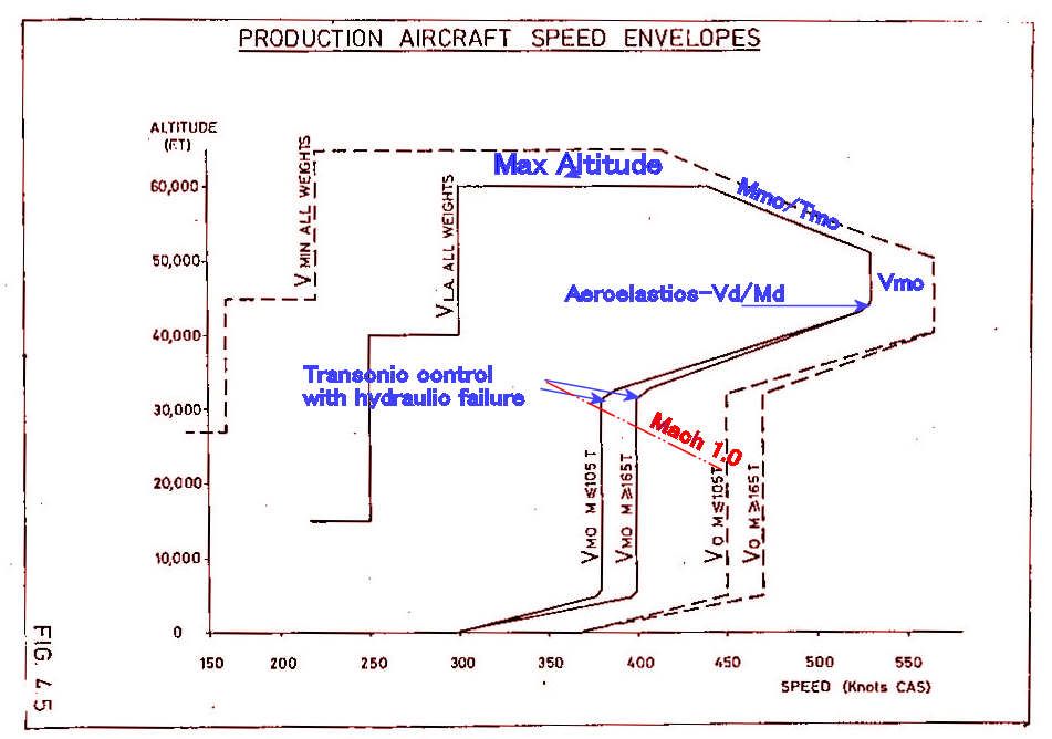
VLA (lowest admissible speed)
One would expect a curve for constant alpha max against IAS and altitude, not the staircase in the diagram.
Was this for simplicity of use of the diagram?[quote]
I don't have a complete explanation for all the regions - it was a long time ago and I'll need to dig, but:
Below 16000 ft Vla obviously needs to go as low as Vref to cover landing at elevated airfield altitudes. At present I don't have a satisfactory explanation for 250 kts between 16000 ft and about 45000 ft (250kts/Mach 1.0) A constant value in IAS is what you would get for a constant CLmax (the alphamax is not really the driver). Vla should give a margin above stall, and a quick sum suggests that 250 kts would be consistent with a 1.3Vs condition and a CLmax of about 0.8 up to Mach 1.0, which is not unreasonable, but I am not saying that is the correct interpretation.
From 45000 ft to 60,000 ft I think Vla may be set by manoeuvre requirements. Certainly the forward CG envelope boundary between 1.0M and 1.5M discussed in earlier posts is very close to the requirement to be able to pull 1.2g with half hinge moment available at Vla and heavy weights. Again not certain, but best guess at the moment.
Yes
[quote ]Mmo (max operating Mach number)
Mach 2.04 is usually quoted as having been chosen to assure an adequate life of the airframe.
But what effect does a higher Mach number as such have?
Or are Mmo and Tmo (127\xb0C) directly related?[quote]
I have always been puzzled by this statement as one does not normally associate Mach Number with a life limit. Going through my collection of lectures I found another, more plausible explanation:
quote" The scheduled cruise mach Number was 2.0. associated with a structural total temperature of 400 degK. Above ISA +5 Mc was cut back to maintain 400 degK.
To cope with variations of flight mach Number about Mc associated with often rapid and significant changes in wind and temperature which occur particularly in the vicinity of the tropopause (which can of course be as high as 60,000 ft in the tropics) a maximum operating Mach Number (Mmo) of 2.04 is selected" unquote [Leynaert, Collard and Brown, AGARD Flight Mechanics Symposium October 1983]
This is much more in line with my memory on this subject.
Yes in principle, but it is a bit chicken and egg, since 530 kts also represents a very good choice for best performance, and I am sure that the stucture would have been built to cope if a higher speed was needed for performance reasons. To the best of my knowledge there is no structural design case that would be critical in this flight regime (other than flutter of course)
Same as earlier - transonic manoeuvre requirements with failed hydraulics, matched to aircraft weight and CG envelope possibilities.
Same again.
I'm not entirely sure, but:
a) there is absolutely no advantage is having a high Vmo at low altitudes as it could not be exploited even if one wanted to because of ATC limitations to 250 kts below 10,000 ft (in the USA at least)
b) there are a lot of things that get rapidly worse if you encounter them at high speed and which are anyway more likely at low altitude - hail, birds etc.
So why store up trouble for yourself!
CliveL
One would expect a curve for constant alpha max against IAS and altitude, not the staircase in the diagram.
Was this for simplicity of use of the diagram?[quote]
I don't have a complete explanation for all the regions - it was a long time ago and I'll need to dig, but:
Below 16000 ft Vla obviously needs to go as low as Vref to cover landing at elevated airfield altitudes. At present I don't have a satisfactory explanation for 250 kts between 16000 ft and about 45000 ft (250kts/Mach 1.0) A constant value in IAS is what you would get for a constant CLmax (the alphamax is not really the driver). Vla should give a margin above stall, and a quick sum suggests that 250 kts would be consistent with a 1.3Vs condition and a CLmax of about 0.8 up to Mach 1.0, which is not unreasonable, but I am not saying that is the correct interpretation.
From 45000 ft to 60,000 ft I think Vla may be set by manoeuvre requirements. Certainly the forward CG envelope boundary between 1.0M and 1.5M discussed in earlier posts is very close to the requirement to be able to pull 1.2g with half hinge moment available at Vla and heavy weights. Again not certain, but best guess at the moment.
Quote:
|
Max altitude (60,000ft)
This is the 'simplest' one: it was the highest 'safe' altitude from which an emergency descent could be made, in the case of a window blowing out, without having the blood of the pax boil.... Test flights (without pax, and with the crew pressure-breathing oxygen) did go as high as 69,000ft. |
[quote ]Mmo (max operating Mach number)
Mach 2.04 is usually quoted as having been chosen to assure an adequate life of the airframe.
But what effect does a higher Mach number as such have?
Or are Mmo and Tmo (127\xb0C) directly related?[quote]
I have always been puzzled by this statement as one does not normally associate Mach Number with a life limit. Going through my collection of lectures I found another, more plausible explanation:
quote" The scheduled cruise mach Number was 2.0. associated with a structural total temperature of 400 degK. Above ISA +5 Mc was cut back to maintain 400 degK.
To cope with variations of flight mach Number about Mc associated with often rapid and significant changes in wind and temperature which occur particularly in the vicinity of the tropopause (which can of course be as high as 60,000 ft in the tropics) a maximum operating Mach Number (Mmo) of 2.04 is selected" unquote [Leynaert, Collard and Brown, AGARD Flight Mechanics Symposium October 1983]
This is much more in line with my memory on this subject.
Quote:
|
Vmo (max operating speed) = 530kts until 43,000ft
I suppose this is related to structural limits (qmax)? |
Quote:
|
Vmo reducing to 380/400kts at about 33,000ft
What is the limiting factor here (other than qmax)? |
Quote:
|
Vmo constant at 380/400kts down to 5,000ft
What is the limiting factor here? The answer will no doubt also explain why this is slightly weight-dependent. |
Quote:
|
Vmo reducing to 300kts between 5,000ft and 0 ft
Why the sudden change below 5,000ft? |
a) there is absolutely no advantage is having a high Vmo at low altitudes as it could not be exploited even if one wanted to because of ATC limitations to 250 kts below 10,000 ft (in the USA at least)
b) there are a lot of things that get rapidly worse if you encounter them at high speed and which are anyway more likely at low altitude - hail, birds etc.
So why store up trouble for yourself!
CliveL
14th Jan 2011, 08:29
permalink Post: 1092
Quote:
| A question I have, relating to the photo above, is about the LE. The LE definately 'droops' in the area ahead of the intakes (it doesn't do so nearer the roots or tips). Is this to provoke a clean flow-breakaway in this area at high angles of attack to encourage the votices to form at this point as the wing transitions to vortex lift? |
The prototype had even more 'droop' in front of the intakes, but that produced a vortex at low incidence (near zero 'g') that went down the intakes and provoked surge.
Quote:
| The wash-out on the tips shows particularly well in the above photo (washout is a forward twist of the wing at the tips to reduce the angle of attack of the tips compared to the rest of the wing, to prevent tip-stalling). |
Cheers
Clive
PS: Everyone seems to be adding their favourite Concorde photograph so I thought I would be different and add my LEAST favourite

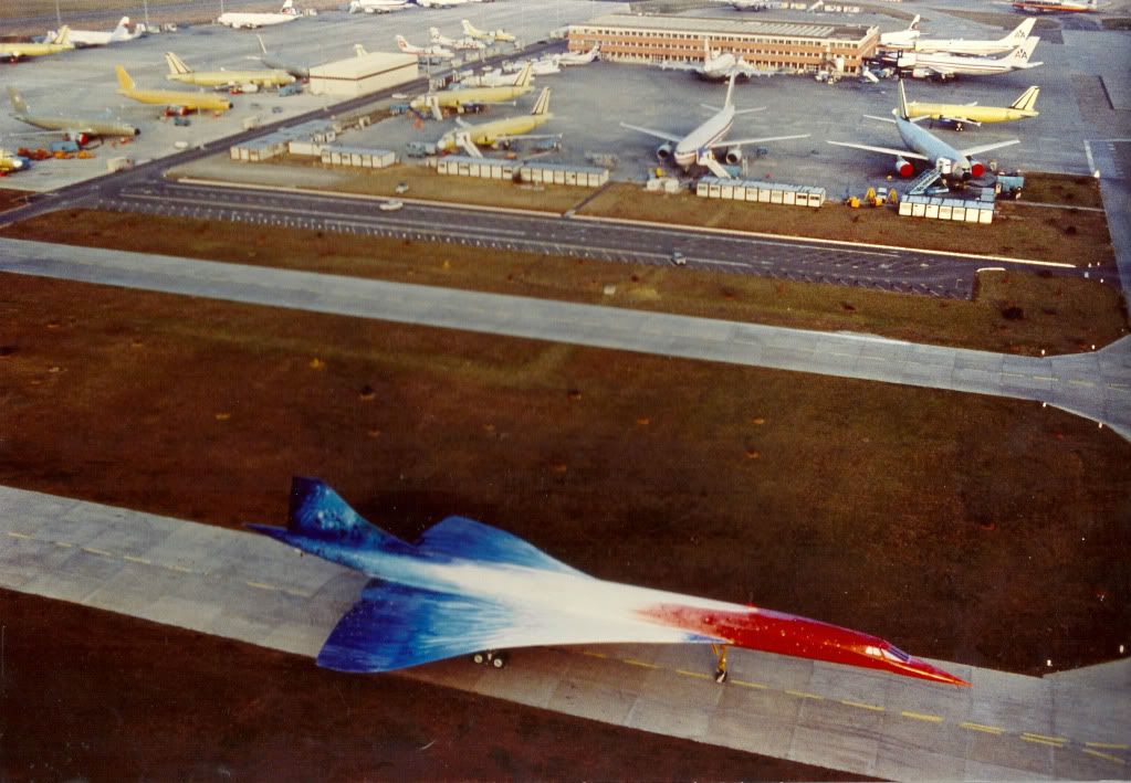 ">
">
Last edited by CliveL; 14th Jan 2011 at 08:43 . Reason: adding a photo and additional remarks
18th Jan 2011, 09:30
permalink Post: 1122
I so remember the BAe AST images from the 1980s, I always thought what a potentially nice looking aeroplane she was. I guess that vastly improving the L/D & T/W ratios could go quite a long way to improving the operating economics, but the noise issue was always going to be the crippler. (I know that they were looking at a 'leaky' version of the OLY593, ie. a very low bypass ratio, but this of course would still not really cut the mustard as far as noise goes). I guess there are no current takers then

Clive, you really surprise me when you say you don't think that composites would be used from a future SST, is there a material reason for this? (I'm curious because being of a simple avionic brain, I always assumed composites would be used. But if anyone knows this stuff, you certainly would Clive ).
).
To answer Mike-Bracknell's original query, as far as avionics goes we can really go to town. For her age Concorde had some truly amazing aircraft systems, for instance the flying controls. To enable mechanical control (both FBW channels failed) there was a highly complex and heavy mixing unit under the rear floor. (To mix pitch and roll pilot mechanical demands into differential elevon demand inputs). This of couse would have to be done away with, as well as the relay jacks and replaced with a pair of side-sticks. (See posts on previous page). A 2 crew operation would obviously be the way to go, but neither desirable or possible in my view when Concorde was designed. A triplex or quadruplex flying control system (possibly even integrating autoflight) would replace the Concorde collection of several analog boxes with a very small handful of lightweight digital units.. The powerplant control will have major weight savings, just take a look at this lot. 8 Engine Control Units, 4 Bucket Control Units, 2 Nozzle Angle Scheduling Units, 4 Reheat Amplifiers, 8 AICUs, 4 Air Intake Sensor Units and a single Air Intake Test Unit could potentially be replaced by just 4 multi-channel EEC type units. (On subsonic aircraft the EECs are mounted on the engine itself, not sure if that's a good idea for an SST, given the operating environment. Air Data and Navigation systems take a major simplification and weight saving, the 3 INUs and 2 ADCs (All of them straight from the 'rent a hernia' store as far as weight goes), could be replaced by a single ADIRU and a SAARU. The fuel indication/management side of things (2 FQI packs, 2 level switching packs and 3 CG computers) would probably be replaced by a single Fuel Processing unit. Ahhhh perchance to dream

Best regards
Dude
Clive, you really surprise me when you say you don't think that composites would be used from a future SST, is there a material reason for this? (I'm curious because being of a simple avionic brain, I always assumed composites would be used. But if anyone knows this stuff, you certainly would Clive
).
To answer Mike-Bracknell's original query, as far as avionics goes we can really go to town. For her age Concorde had some truly amazing aircraft systems, for instance the flying controls. To enable mechanical control (both FBW channels failed) there was a highly complex and heavy mixing unit under the rear floor. (To mix pitch and roll pilot mechanical demands into differential elevon demand inputs). This of couse would have to be done away with, as well as the relay jacks and replaced with a pair of side-sticks. (See posts on previous page). A 2 crew operation would obviously be the way to go, but neither desirable or possible in my view when Concorde was designed.
A triplex or quadruplex flying control system (possibly even integrating autoflight) would replace the Concorde collection of several analog boxes with a very small handful of lightweight digital units.. The powerplant control will have major weight savings, just take a look at this lot. 8 Engine Control Units, 4 Bucket Control Units, 2 Nozzle Angle Scheduling Units, 4 Reheat Amplifiers, 8 AICUs, 4 Air Intake Sensor Units and a single Air Intake Test Unit could potentially be replaced by just 4 multi-channel EEC type units. (On subsonic aircraft the EECs are mounted on the engine itself, not sure if that's a good idea for an SST, given the operating environment. Air Data and Navigation systems take a major simplification and weight saving, the 3 INUs and 2 ADCs (All of them straight from the 'rent a hernia' store as far as weight goes), could be replaced by a single ADIRU and a SAARU. The fuel indication/management side of things (2 FQI packs, 2 level switching packs and 3 CG computers) would probably be replaced by a single Fuel Processing unit. Ahhhh perchance to dream
Best regards
Dude
12th Apr 2011, 05:47
permalink Post: 1295
Quote:
| Basically, a relatively small failure within the intake/spike structure of the SR71 engine, was enough to simply tear the airframe apart within seconds of onset. |
Quote:
|
Jim Zwayer, Lockheed flight-test specialist, and I were evaluating systems on an SR-71 Blackbird test from Edwards. We also were investigating procedures designed to reduce trim drag and improve high-Mach cruise performance. The latter involved flying with the center-of-gravity (CG) located further aft than normal, reducing the Blackbird's longitudinal stability.
On the planned test profile, we entered a programmed 35-deg. bank turn to the right. An immediate unstart occurred on the right engine, forcing the aircraft to roll further right and start to pitch up. I jammed the control stick as far left and forward as it would go. No response. I instantly knew we were in for a wild ride. The cumulative effects of system malfunctions, reduced longitudinal stability, increased angle-of-attack in the turn, supersonic speed, high altitude and other factors imposed forces on the airframe that exceeded flight control authority and the Stability Augmentation System's ability to restore control. The next day, our flight profile was duplicated on the SR-71 flight simulator at Beale AFB, Calif. The outcome was identical. Steps were immediately taken to prevent a recurrence of our accident. Testing at a CG aft of normal limits was discontinued, and trim-drag issues were subsequently resolved via aerodynamic means. The inlet control system was continuously improved and, with subsequent development of the Digital Automatic Flight and Inlet Control System, inlet unstarts became rare. |
21st Jun 2011, 15:45
permalink Post: 1388
A Side Sticky Subject
As I recall, they referred to this research project as a CCV (Controlled Configured Vehicle) design study. It would be great if we could get this confirmed, but they talked about subsonic drag reductions of 10 to 15% by flying (not taking off!!) with a far more aft CG than the norm. The 'system' I seem to remember, as a result naturally commanded some down elevon, which increased lift. As the aircraft could then fly with less alpha, I guess this is where the drag reduction comes from. (Clive, I wonder if you could find out through one of your contacts if this was true?).
I'd still personally like to know how the sidestick was integrated into the flying control system, I've been thinking and can not now believe that sidestick inputs could be simply input to the flying control system 'at resolver level'. Remember that the concept of the FBW system on Concorde was that resolvers were utilised as simple 4 wire synchros, and the pitch and roll axis utilised a CX/CDX/CT chain, which produced the error signal to the ESA's in the Autostab computers. Using a sidestick completely breaks up the chain, and my guess is that a seperate digital unit contained the flight rules which were summed against PFCU CT position and sidestick input would have been necessary. It is possible then that an analog output from this 'box' could be fed to the Autostab Computer ESAs and hence drive the elevons. I'm probably completely wrong, but I'd surely still love to know the truth. As you say Clive, ideal stuff for Concorde 2.
Best regards
Dude
Last edited by M2dude; 21st Jun 2011 at 18:53 . Reason: A fine wine may improve with age... my spelling however doesn't
21st Jun 2011, 18:50
permalink Post: 1389
Don't need no contacts Dude. The drag reduction came simply from flying at a lower AoA when trimmed at an aft CG. Less 'up' elevon, which is similar but not the same as 'down elevon' in an absolute sense, so less adverse elevon lift and work the wing to a lower AoA in consequence. Just an extension of the basic Concorde certification with a 'point' TO CG really.
They were certainly looking to study control laws that allowed flight at very aft CGs to increase aircraft performance, so yes, this was a CCV exercise, but they were also seeking experience with digital control and system architectures that could be transferred to other active control applications.
The 'sidestick' arrangement was virtually a complete A320 style arrangement using two computers and digital signalling throughout. For just 10 hrs they wouldn't need anything more complicated than a 'panic switch' to return control to the standard Concorde green system that was still there and available.
Clive
21st Jun 2011, 19:59
permalink Post: 1391
Shirley the aft CG research for lower cruise drag could equally be done with conventional Concorde controls? Why is it associated only with sidestick control?
24th Jun 2011, 00:15
permalink Post: 1399
<<
I'm guessing you mean rate of climb rather than IAS?
>>
<<No, I meant the airspeed you'd be flying at while climbing (post takeoff)>>
OK, then the answer to your Q's:
Also what was the typical climb speed
- At lift-off? About 200kts
- Once 240 kts is achieved? 240kts
- At minimum maneuvering speed at typical takeoff weight? Vla after takeoff was V2 until 15,000'. I.E. about 220kts
- At MTOGW? V2 didn't vary much by weight
Out of JFK we flew at Vmo once further than 12nms from the coast. Vmo=400kts IAS at low level.
Out of LHR overland the IAS restriction was 300kts until past the speed limit point early in the SID - much less draggy than 250kts and hence better climb rates. But you'd quickly be released to get to 400kts (barder's pole) where it was designed to be flown.
<<Why higher speed? That have to do with shockwaves and the resulting pressure distribution differences?>>
The flight envelope was bigger and more complex than subsonic types: it was developed in flight test and probably had many considerations involved. I think someone posted it earlier in this thread in graphical form (from the flight manual) if you want to see it. In practice, you had to be aware of three basic parameters - IAS, Mach and CG position (the CG "corridor"). Once understood, it wasn't that difficult to keep up with it...and the IAS and Machmeters had barber's poles handily programmed to show the limiting values (including, cleverly, max temp on the nose Tmo=127 degrees celcius).
Regarding climb rates - best ROC was at 400kts (MTOW) or 380kts (MLW). As speed reduced below that, drag increased and ROC reduced. At MTOW and 400kts you'd get about 4000fpm max dry power. At 250kts it was all noise and very few feet per minute - after noise abate procedures you had to lower the nose, just barely climb, and get IAS up toward min drag as soon as possible. With an engine failed go for 300kts minimum - Vmo as soon as you can.
<<shockwaves and the resulting pressure distribution differences>>
You had to avoid the "transonic" region due to these effects: maximum subsonic cruise was 0.95M due to the auto-stabilised flying controls become over-active as shockwaves started to "dance" around the airframe (usually asymmetrically). This calmed down by about 1.3M in the acceleration (when the intake ramps started to do their thing). To accelerate to 2.0M you needed reheat until 1.7M so you didn't hang around between 0.95M and 1.7M. FL260 was best for subsonic cruise because at that level 400kts IAS = 0.95M...
Last edited by NW1; 24th Jun 2011 at 09:09 .
17th Dec 2011, 23:35
permalink Post: 1536
Re : 9min to mach 2.
Not sure you can get CG back that quickly.
In the (restored) Sim with a lightweight fuel load that will not get you anywhere and not bothering about the CG, the absolute minimum time to Mach 2 at 50,000ft on a pretty constant VMO chase is just over 15mins, so really unlikely that this was possible in real life....but will stand corrected if someone says other wise.
The A/C had diverted to cardiff as they had suffered a engine surge due to a double intake lane failure and had to slow to subsonic early. That coupled with additional time with engines running at JFK meant they were just not comfortable about coming to London and possibly declaring a fuel emergency.
6th Apr 2012, 19:42
permalink Post: 1587
Vmo
Last time I logged in someone was asking why the Vmo/Mmo was the way it was, but it seems to have disappeared along with Bellerophon's suggestion that someone else might be able to throw some light on it. This might help.
SORRY - senior moment - this should have been posted on another thread!
To be honest I can't remember exactly why 530 kts was chosen for the supersonic Vmo, but it was probably the best climb speed.
Mmo/Tmo was limited by a combination of intake and structural temperature.
The 'cut-off' in the sloping/530 kts boundary was, if I remember correctly, to avoid a minor aeroelastic problem at the Vd/Md condition one arrived at from that corner.
The variation of Vmo with weight was a device which, when associated with the CG corridor, allowed the aircraft to meet the manoeuvre requirements when flying on half hydraulics.
400 kts CAS gave 0.93M at around 28000 ft if I recall correctly, which was just below drag rise and gave optimum subsonic cruise performance
Last edited by Jetdriver; 21st Apr 2012 at 00:33 .
7th Jul 2012, 06:03
permalink Post: 1649
Quote:
|
Originally Posted by
galaxy flyer

Four engine flameout is a very unlikely event, unless one runs into a volcanic cloud.
GF |
I'm pretty sure my memory isn't betraying me too far when I say I seem to remember a case, in the dim and distant past, of a management pilot (no less) taking a Concorde sector and... mismanaging things... badly. In fact they came so close to a four engine flameout (with no volcanic cloud in sight) that the thing was unable to be disembarked after landing for... CoG reasons... if you take my meaning!
Someone confirm?
R1
Last edited by Ranger One; 7th Jul 2012 at 06:04 .