30th Sep 2010, 13:58
permalink Post: 499
As promised here are the answers to our trivia quiz.
Actually there were 14 (but if you are not necessarily a Concorde person, 13 is acceptable). There were '13 fuel tanks, numbered 1 - 11' as we used to tell all the visitors to the aircraft, (The wingtip tanks 5A & 7A making up the extra 2) PLUS a single small
scavenge tank
at the rear of the aircraft that was used to remove fuel from the vent lines and return this fuel via a transfer pump back to tank 3. (A fuel level sensor would trigger the pump with only 1 US Gallon of fuel in the tank). If the trim gallery became over-pressurised (ie tank 3 already full to the brim) an overflow relief valve (ORV) underneath the rear of the aircraft would open and dump the contents of the tank overboard. There was a flight deck indication if the scavenge pump was running in flight to give the crew an indication that a tank somewhere was probably over-filling and to take the appropriate action. There was one added goody about the ORV; If you were on the ground with the refuel door open and due to a refuelling overfill anywhere, fuel entered the scavenge tank, at 7 gallons the ORV would open and rapidly dump the fuel on the floor. For this reason a vent pipe and fuel drum was often placed underneath the ORV during high load refuels. If this was not fitted and you just happened to walk underneath the aircraft at the wrong moment during fuelling........

As a total aside to all this (or me going off on a tangent yet again) the fuel tanks themselves were gently air pressurised above 44,000' to around 2.2 PSIA. This was to prevent the beginnings of any boiling of the fuel in the tanks, due to the low ambient pressure/high fuel temperatures, causing pump cavitation. (Boiling itself could not occur much below 65,000'). A small NACA duct at the right side of the fin was used to supply the ram air for tank pressurisation, the two vent valves in the tail cone, one per trim gallery, closing off automatically at around 44,000', the pressure being controlled by a pneumatic valve, with full automatic over-pressure protection. OK sorry guys and gals, back to the answers:
This is the stinker.... there were 114 (although at entry into service there were 115!!). 100 passenger seats + 6 cabin crew seats + 5 flight deck seats (including the fold up seat in the aisle at the rear) PLUS 3 LOO SEATS (Originally 4 loos, the fourth loo being removed in the early 1980's).

50,189' and 530 KEAS, but we'll settle for anything around FL500 being correct.

Aircraft 216, G-BOAF, the last Concorde ever built. When 216 first flew in 1979 she was a variant 192 'British Unsold Aircraft' and was registered as G-BFKX. In late 1979, BA purchased the aircraft and it was subsequently converted to a Type 102 British Airways variant, and after modifications were complete, test flights were carried out from Filton under the registration of G-N94AF. This registration was to enable the aircraft to participate in the Braniff interchange between IAD and DFW, but when the Braniff Concorde adventure unfortunately ended in 1980, she was again re-registered to G-BOAF, this is how she was delivered to BA later that year.

Easy one this I hope; 60.000'. (As we've said before this limitation was imposed because of the dual window failure / emergency descent time consideration, not as a performance issue. On test flights 63,000' was routinely attained, and altitudes of up to 68,000' were achieved during development flying. (On her maiden flight, G-BOAB achieved 65,000' and Mach 2.04; the first British constructed Concorde to achieve Mach 2 on her maiden flight, and the ONLY one of the original five BA aircraft to achieve this).
Hopefully an easy one... there were TWELVE: 2 nose wheels, 8 main wheels and 2 tail wheels. (No, even I'm not nasty enough to include the wheels on the bar trolleys
 ). Oh, and there were 9 wheel brakes, one for each main wheel and as was mentioned in a previous post, a single steel disc brake for the nose wheels (the nose having a live axle), for automatic use during gear retraction only.

Three modes; Blue electronic signalling, green electronic signalling and mechanical signalling. I suppose we COULD be pedantic here and include the Emergency Flight Control mode where even with a jammed control column/control wheel, strain gauges (and Safety Flight Control Computers of course) would still enable you to control the elevons.
OK, three basically. Up (Duh!), 5 degrees for taxi/take off and low speed flight and 12.5 degrees for landing. As ChristiaanJ quite rightly pointed out in an earlier post, the prototype (and pre-production) aircraft landing position was 17.5 degrees of droop. (In my view the nose of the aircraft looked a little like an armadillo in this extreme configuration).

In 1977 the new digital Plessey PVS 1580 Aircraft Integrated Data System was progressively fitted to the BA fleet, this being the first microprocessor application on Concorde, this application being followed in several other systems during the life of the aircraft. The 'final' applications being TCAS and the superb retrofitted Bendix RDR-4A weather radar system.

No we are not including torch batteries and emergency lights etc.
 There were a total of seven main power sources: 4 x 60KVA AC generators, one per engine, a single 40KVA hydraulically powered emergency generator and 2 lead acid (or ni-cad in the case of G-BOAG) main aircraft batteries. (Not a terribly Re-Volting question I hope).

I hope this quiz was fun and not too perplexing to any of you guys.
Dude
Quote:
| 1) How many fuel tanks were there on Concorde? |
As a total aside to all this (or me going off on a tangent yet again) the fuel tanks themselves were gently air pressurised above 44,000' to around 2.2 PSIA. This was to prevent the beginnings of any boiling of the fuel in the tanks, due to the low ambient pressure/high fuel temperatures, causing pump cavitation. (Boiling itself could not occur much below 65,000'). A small NACA duct at the right side of the fin was used to supply the ram air for tank pressurisation, the two vent valves in the tail cone, one per trim gallery, closing off automatically at around 44,000', the pressure being controlled by a pneumatic valve, with full automatic over-pressure protection. OK sorry guys and gals, back to the answers:
Quote:
| 2) How many seats were there? |
Quote:
| 3) At what approximate altitude and KNOTS EAS was Mach 2 achieved? |
Quote:
| 4) Only one BA Concorde had three different registrations, what was it? |
Quote:
| 5) What was the maximum permitted altitude in passenger service? |
Quote:
| 6) How many wheels on the aircraft |
). Oh, and there were 9 wheel brakes, one for each main wheel and as was mentioned in a previous post, a single steel disc brake for the nose wheels (the nose having a live axle), for automatic use during gear retraction only.
Quote:
| 7) How many flying control modes were there? |
Quote:
| 8) How many positions of nose droop were there? |
Quote:
| 9) What was the first microprocessor application on the aircraft? |
Quote:
| 10) How many main electrical sources were there? |
There were a total of seven main power sources: 4 x 60KVA AC generators, one per engine, a single 40KVA hydraulically powered emergency generator and 2 lead acid (or ni-cad in the case of G-BOAG) main aircraft batteries. (Not a terribly Re-Volting question I hope).
I hope this quiz was fun and not too perplexing to any of you guys.
Dude
2nd Oct 2010, 08:45
permalink Post: 508
CRON
I can only speak here from the Concorde ground engineering school that I attended over a total of 13 weeks at Filton in 1980 and 1981; the pilot/flight engineer questions there were I'm sure FAR nastier (and also more operationally specific); we did get to share simulator time though, which was really useful. Like the aircrews, we stayed up in a hotel in Bristol during the week. (I personally had only left BAC, as it was then, for BA at Heathrow in late July 1977, so I was returning to familiar pastures). The exam format would be several dozen multi-choice questions per week/phase; a typical question would go something like:
The Inner Elevon Light, plus 'PFC' red Master Warning is triggered by:
a) The Green Flying ControlComparator
b) The Blue Flying Control Comparator
c) Either Comparator
The correct answer is (b).
Another flying controls question I can remember is:
Outer Elevon Neutralisation is triggered at:
a)Vmo + 10 KTS
b)Vmo + 15 KTS
c)Vmo + 25 KTS
The correct answer here is (c).
The pass mark in these exams was 75%, with penalty marking applied for any wrong answers. I always found the worst part was the fact that the exams were on a Friday afternoon after lunch
Nick Thomas
Hi again Nick, one really for the likes of BRIT312, EXWOK etc, but there was, as was mentioned before, an emergency forward transfer switch in the roof panel above the pilots (F/O's side if I remember correctly). When placed to the emergency poition two electric and two hydraulic fuel pumps for the rear trim tank #11 would start up automatically, as well as the forward tank inlet valves being opened also.
From what you said about the 'lady' being ahead of her time, I would certainly agree with you here; in my view she was generations ahead of everything else.
nomorecatering
The BA simulator that resided at Filton has been re-located to Brooklands Museum, and has been re-activated, but without motion and I'm not sure about full visuals either. I've not seen it myself yet, but I'm told that things have progressed really well with the operation. Obviously it is no longer certified as an active simulator; I'm not sure about the situation in France, perhaps my friend ChristiaanJ can answer that one.
I seem to remember typical loads for LHR-JFK being around 93-96 tonnes, depending on the passenger load and en-route conditions. Full tanks, depending on the SG was around 96 Tonnes. High fuel temperatures in the summer were a major pain; restricting maximum onload due to the low SG.
As far as ground school notes, mine are all out on long term loan (MUST get them back). The ground school are totally priceless and I am sure that there are many complete sets lying around in atticks/bedrooms/garages/loos etc.
Dude
Quote:
| If I may ask - and folk can recall - what would a sample question look like from these exams? |
The Inner Elevon Light, plus 'PFC' red Master Warning is triggered by:
a) The Green Flying ControlComparator
b) The Blue Flying Control Comparator
c) Either Comparator
The correct answer is (b).
Another flying controls question I can remember is:
Outer Elevon Neutralisation is triggered at:
a)Vmo + 10 KTS
b)Vmo + 15 KTS
c)Vmo + 25 KTS
The correct answer here is (c).
The pass mark in these exams was 75%, with penalty marking applied for any wrong answers. I always found the worst part was the fact that the exams were on a Friday afternoon after lunch
Nick Thomas
Quote:
| So I have been wondering if there were any special procedures for managing the CofG in a rapid descent especially as there could also be many other factors needing the crews attention? |
From what you said about the 'lady' being ahead of her time, I would certainly agree with you here; in my view she was generations ahead of everything else.
nomorecatering
Quote:
| Are there any concorde simulators that are still working and retain their certification? |
Quote:
| Regarding LHR JFK routes. What was the avarage fuel load and how close to full tanks was it. |
As far as ground school notes, mine are all out on long term loan (MUST get them back). The ground school are totally priceless and I am sure that there are many complete sets lying around in atticks/bedrooms/garages/loos etc.
Dude
Last edited by M2dude; 2nd Oct 2010 at 13:40 .
9th Oct 2010, 19:26
permalink Post: 540
DavvaP
There was one small part of the 'B' model that did find it's way into the production aircraft by way of a retro-fit in the late '70's.: The leading edge of the dorsal fin was re-profiled, taking out the original 'dog leg' and the flying control surfaces were slightly extended. The whole exercise was one of supersonic drag reduction, although I never saw the actual gains quantified. (It was due to the extensions of the elevons and rudders that water ingress caused failures in later years. I just hope the fuel, if any, we saved was worth the trouble
).
As far as ChristiaanJ's point about the Olympus; the only plans I ever saw were for the Olympus 593 Mk 622, which gave a thrust increase of around 4,000 lbs static thrust but retained reheat. I know there were definate plans for a larger diameter engine (not just the LPC) that would have naturally required a larger intake. As far as the intake irself went, believe it or not, the plan was to remove the rear ramp altogether.
The 'B' would have been a hell of an aeroplane; but the 'A' was still absolutely amazing in any case.
Dude
Quote:
| Long time admirer of the marvel that is Concorde - but no aviation expert at all, just appreciate true genius and beauty! One question I've got is about the Concorde "B". Given it was never built, was there ever a plan to retro-fit some of the modifications back into one of the existing airframes? Specifically I'm thinking the engine - which on its own should have given a large boost to range (or savings on fuel!). |
).
As far as ChristiaanJ's point about the Olympus; the only plans I ever saw were for the Olympus 593 Mk 622, which gave a thrust increase of around 4,000 lbs static thrust but retained reheat. I know there were definate plans for a larger diameter engine (not just the LPC) that would have naturally required a larger intake. As far as the intake irself went, believe it or not, the plan was to remove the rear ramp altogether.
The 'B' would have been a hell of an aeroplane; but the 'A' was still absolutely amazing in any case.
Dude
12th Oct 2010, 12:21
permalink Post: 562
Zimmerfly
I have to echo Landlady's comments. This has really been done to death in various forums (yawn!) , and people forget (or perhaps never knew in the first place) just how much vital work the captain in question did for the whole Concorde operation. (Including for example, personally negotianing with HMG regarding BA taking over the Concorde support costs etc, and forming and heading up the division that saw Concorde transformed from a loss making burden into a major profit centre for the airline). Also he was GM Concorde Division and not Chief Pilot.
To answer Steve's original TECHNICAL question; you must remember that using fuel for trimming was to offset long term changes in the centre of lift and not any short term stabilty shifts during landing. (The combination of pilots and elevons coped with that quite admirably
). And around four tonnes WAS transfered into tank 9 after landing, in order to aid ground stability, particularly during disembarkation.
landlady
I hope you are having a great time sunning yourself ('aint jealous, honest
) and have a rum punch or two for me.
V1...Oops
This site you mentioned is definately worth a visit; there are some great images there.
Dude
5th Nov 2010, 11:56
permalink Post: 663
I have to admit that some of the subsonic fuel burn figures for Concorde were truly eye watering, and without massive engine and airframe modifications there was precious little in service that could be done to improve things. Paradoxically improvements to the
supersonic
efficiency of the powerplant were easier to implement, and several modifications were implemented, tried or proposed to improve fuel burn:
Way back in the late 1970's we did a major modification to the intakes that increased capture area by 2.5% and gave us typically a 1.6% improvement in trans-Atlantic fuel burn, and although this was our biggest performance improvement modification, there were more:
The famous elevon and rudder trailing edge extension modifications (that due to poor design, produced in later life the water ingress induced honeycomb failures) together with the re-profiled fin leading edge modification, I never saw the performance gains quantified (anyone have any ideas?).
Can anyone here remember the riblet trial? In the mid 1990's Airbus supplied 'stick on' plastic riblets, applied to various areas on the under-side of the wing on G-BOAG. These riblets had very fine undulations moulded into the surface; the idea being that as the air flowed through and around the riblet patches, boundary layer turbulence, and hence induced drag would be reduced. Now, the performance gains (if any) were never quantified, mainly because the riblet patches either peeled off or the surface deteriorated with the continuous thermal cycle. (I was over in JFK when the aircraft first arrived after having the riblets fitted, and as the crew were trying to proudly show me these amazing aerodynamic devices, they were sadly embarassed, as several had dissapeared in the course of a single flight).
There was one modification, proposed by Rolls Royce in the late 1990's that did have quite a lot of potential; this was to increase the engine N1 by around 1.5%. This would have had the effect of increasing engine mass flow and therefore reducing the drag inducing spill of supersonic air over the lower lip of the intake. Depending on the temperature, the performance gains were in the order of a 1.5% improvement in fuel burn at ISA Plus upper atmosphere temperatures ('normal' LHR-JFK) to none at all at significant ISA Minus temperatures (LHR -BGI). The modifacation had been trialed on G-BBDG before her retirement in the early eighties, and was proven in terms of performance enhancement and engine stability. In order to keep TET at the pre-modification level, there was a small increase in N2 commanded also. (The higher N1 required an increase in primary nozzle area, reducing TET). The main reason for the modification not being implemented was one of cost; The Ultra Electronics Engine Control Units were analog units, and the modification was a simple replacement of two resistors per unit. However because ultimate mass flow limitation was also controll by the digital AICU (built by British Aerospace Guided Weapons Division) the cost of getting a software update for this exremely 'mature' unit was found to be prohibitive.
A certain 'brainy' SEO and myself were working on a modification to improve fuel burn on ISA minus sectors. The idea was to force the autopilot, in Max Cruise at low temperatures only , to fly the aircraft close to Mmo, rather than at Max Cruise speed of Mach 2 - 2.02; this would have given us gains of up to 1%, depending on the temperature. The basic electronics involved for the modification were relatively straightforward, but it was never pursued due to the complexity of dealing with temperature shears and the cost of certification.
Dude
Last edited by M2dude; 5th Nov 2010 at 15:49 .
23rd Nov 2010, 17:16
permalink Post: 762
Gents and Gent'esses,
Regarding the rather important role of the elevons on Concorde
where there any failures during her time in the skies ?
regards,
d
Regarding the rather important role of the elevons on Concorde
where there any failures during her time in the skies ?
regards,
d
24th Nov 2010, 13:43
permalink Post: 764
Quote:
|
Originally Posted by
speedbirdconcorde

Regarding the rather important role of the elevons on Concorde
were there any failures during her time in the skies ?
|
M2dude may already have the details of "where", "when" and "how many" at his fingertips.
Otherwise a Google, with terms such as 'AAIB', 'DGAC', 'elevon failure' and suchlike in the query, should get you the answers.
The failures were similar to the rudder failures: part of the trailing edge of an elevon parting company with the aircraft, noticeable because of vibration, but without dire consequences.
CJ
26th Nov 2010, 08:47
permalink Post: 781
speedbirdconcorde
Yes we did, just a couple if I remember correctly and relatively minor failures at that. (Regular ultrasonic NDT inspections had been instigated to pre-empt these failures from actually occuring). New elevon purchases were rightly seen to be the answer to the problem; the poorly designed trailing edge extension modifications of the late 1970's were as was said before, the source of these failures, due to moisture ingress in the honeycombe structure).
Mr Vortex
As has been posted previously, there was a small NACA duct on the right hand side of the fin, that provided the air source for fuel tank pressurisation. This pressure was controlled to 1.5 PSIG.
This switch operated two valves that would drain out any residual fuel for maintenance (for example, replacing a vent valve); it was not used very often however.
Islander539 and ChristiaanJ
The actions of Airbus at Filton are nothing short of disgusting. By 'removing the insulation' you will need to strip the cabin completely bare (seats, galleys, ceiling panels and all of the side-wall panels). They say that 'Filton was only ever going to be an interim home for Concorde', what total
crap
!!
The idea is to 'cocoon' the aircraft 'until a permanent home is found'. I hope all readers here realise that this will involve BREAKING UP THE AIRFRAME to make it road transportable. The reasons that scarebus are giving for all this are vague and misleading, but here's my take. There are pressures around from various people and bodies 'to return a British Concorde to flying condition.' Now a lot (NOT ALL) of these people although very well intentioned are not that well informed and their wishes are not reasonably possible. But the pressures exist nonetheless, and scarebus will do anything to prevent this possibility, nomatter how unlikely, from being progressed. So we have G-BOAF, the youngest Concorde in the world, with the lowest airframe hours, in pretty good structural condition (she's suffered from being outside for 7 years, but nothing terminal) and actually in the hands of the dreaded scarebus (who would rather forget that Concorde ever existed, and was almost certainly the reason why they even noe exist). Doesn't take much working out now, does it?
Dude
Quote:
Regarding the rather important role of the elevons on Concorde
 where there any failures during her time in the skies ?
|
Mr Vortex
Quote:
|
I've just wonder that does the Concorde use a surge tank or
some a kind of a NACA duct like on B737 for pressurize the fuel in a tank? |
Quote:
Also, in Concorde F/E panel around the fuel control panel there're switch call trim pipe drain switch. Which I tried to read and figure it out but finally I don't know what it actually do
 and in which circumstance do we need to use it
|
Islander539 and ChristiaanJ
The actions of Airbus at Filton are nothing short of disgusting. By 'removing the insulation' you will need to strip the cabin completely bare (seats, galleys, ceiling panels and all of the side-wall panels). They say that 'Filton was only ever going to be an interim home for Concorde', what total
crap
!!
The idea is to 'cocoon' the aircraft 'until a permanent home is found'. I hope all readers here realise that this will involve BREAKING UP THE AIRFRAME to make it road transportable. The reasons that scarebus are giving for all this are vague and misleading, but here's my take. There are pressures around from various people and bodies 'to return a British Concorde to flying condition.' Now a lot (NOT ALL) of these people although very well intentioned are not that well informed and their wishes are not reasonably possible. But the pressures exist nonetheless, and scarebus will do anything to prevent this possibility, nomatter how unlikely, from being progressed. So we have G-BOAF, the youngest Concorde in the world, with the lowest airframe hours, in pretty good structural condition (she's suffered from being outside for 7 years, but nothing terminal) and actually in the hands of the dreaded scarebus (who would rather forget that Concorde ever existed, and was almost certainly the reason why they even noe exist). Doesn't take much working out now, does it?
Dude
7th Dec 2010, 22:18
permalink Post: 840
Wow thanks a lot M2Dude for your diagram.
I'm wonder that did Concorde has a neutal of stable stability? Did the elevon work out the same job to produce the stability like the elevator and stabilizer?
Also, I have read your post and wonder why when the temp fall below ISA-7, the AICU order the N1 to decrese?
And the final question. In the early concorde, does the pilot has ability to select the amount of afterburn thrust by rotate the area knob is that right? and why the airline remove it?
Thanks for your reply.
Best Regards
8th Dec 2010, 18:05
permalink Post: 841
Landroger
The great thing about the OLY593 was the high specific thrust (in relative terms the Olympus is a tiny, compact design), it's growth potential/high potential mass flow. A bypass engine is not really ideal for supersonic cruise, and given what was available in terms of two-spool turbojets in the 1960s, the Olympus was the obvious choice for both the TSR-2 and Concorde alike. As far as for ships and power stations, well a turbojet is always going to be favourite, as all the gas energy is contained in the jet efflux; this can be efficiently transferred to the load in question by a gearbox coupled to the HP spool.
howiehowie93
Well the 593 did require a primary nozzle to match N1 against N2, bur apart from that she was a study of deceptive simplicity and elegance.
No mate, generally BI-HEX AF.
This really is fascinating stuff Howie, thank you. As I alluded to a few pages back, the primary nozzle on the OLY593 opened in response to the rising P7, kind of 'after the horse has bolted' in a way. To maintain the correct scheduled value of N1, the control system set, via a needle valve, a finite ratio between P7 and P3. As reheat lit as P7 attempted to rise it upset this ratio and the primary nozzle was opened in order to restore the aforementioned ratio. (Nozzle opens, P7 falls). When reheat was cancelled the opposite happened, and the nozzle closed sharply to prevent N1 overspeed.
Tom355UK
Glad you are enjoying our thread, and thank you for your kind words. (But apologies to your good lady wife though
 ).
).
Jeepers Tom that is one hell of a question. Assuming there was a market for such a venture (personally not sure right now) I think you are looking at BILLIONS of $, and for this reason alone I think you'd find that a multi-national/continental effort would be required. There is little doubt that technology is not the major barrier here, but economics and political will. (Nice thought though, I do agree).
As far as a powerplant goes, well the PW5000 is a really superb engine, although well down on the thrust requirement for an 'NG' SST. More likely I would have thought would be e development of the Olympus, there was/is still such an enormous amount of potential in this basic design. (But who knows, this is all pure speculation anyway).
And have no fears about posting here Tom, most of us are quite happy to answer away (We've said before that there is no such thing as a stupid question; you are most welcome here
).
DavvaP
It really did not matter what airframe we used for the test flight; the sole purpose was just to find out just what effect (if any) the tank liners had on the performance of the fuel system. (The handsome chap who you see on TV most, installing the liners, Mr Marc Morley left BA and now resides in Australia).
I am honoured to say that I was lucky enough to be onboard G-BOAF for that flight from LHR-BZZ and as far as I could tell, the liners had no impact whatsoever. One amusing
part of the flight was when we deliberately allowed tank 3 to run dry and see just what the indicated fuel quantity was as #3 engine flamed out (we were subsonic at this point of course). The gauge slowly crept down (in order for the tank to to run dry, the tank 7 & 8 transfer pumps were switched off) and we all watched in eager anticipation/dread....... as the counters reached zero weeeeeee... the engine flamed out. I am being completely honest here, the engine wound down EXACTLY at
ZERO
indicated contents).
Those 7 aircraft really did look magnificent I know, it was just sad as to the reason they were all lined up there.
Mr.Vortex
Well she was a delta without a tailplane, so the short answer is 'yes', but remember that we used fuel to move the CG backwards and forwards for long term trimming.
OK, this is a little complicated, so bear with me. The intake had a finite limit, in terms of the mass flow that it could deliver to the engine and so an automatic N1 limitation signal was transmitted from the intake 'box' (the AICU) to the engine 'box' (the ECU) full time above Mach 1.6. Now this limitation was referenced against TEMPERATURE compensated N1, (
N1/
\xd6
q)
and at normal ISA temperatures this limit was above the 'normal' 101.5% N1 running line. (The lower the temperature, the lower the effective limit became). At ISA -7 the limit now became less than 101.5% N1, and so the demanded value of N1 was reduced to this value. But this limit signal was always there, it's just that at normal temperatures it was effectively ignored by the ECU. If this limitation signal failed for any reason, the AICU would detect this by way of the ramp angle becoming uncomfortably close to it's MINIMUM variable limit (this limit was scheduled as a function of intake local Mach number) and an amber light would illuminate on the associated N1 gauge, along with an amber INTAKE master warning would illuminate (plus an audible 'BONG' from the audio warning system). The only course of action was to manually reduce throttle setting away from the Mach 2 norm of maximum, in order to reduce N2, and consequently N1 and mass flow demand. There was in intake pressure ratio indicator at the top of the intake control panel that would show where the power setting would have to be set to. It was an indirect indication of intake shock geometry.
This manual N1 datum reset control was only used during flight test trials into just how much N1 would have to be controlled/reduced at low temperatures in order to give optimim intake geometry. It had absolutely nothing to do with afterburner/reheat and had no place in the production aircraft as all the research was complete
Best regards to all
Dude
Quote:
| Which brings me to my questionette - given that Bristol-Siddley created the original design when jet travel was still quite novel, what was it about the Olympus that made it so capable in so many guises and for so long? Not only Concorde of course, but TSR2, warships and fixed electrical generators. |
howiehowie93
Quote:
| The Olympus - nowt ! Two Spools and a Fuel Valve thats your lot. nothing to go wrong and being an Aeroderivative all the ancillary equipment is either bolted on underneath or away from the engine outside the enclosure. |
Quote:
| Was it all still BSF on the 593? |
Quote:
| oh ! I forgot about the Hot Shot; when I was ground running installed RB199's there was no jump in TBT/T7, you couldn't sense it fire either, the only feel was either the Reheat lighting off with a big roar or the engine going quiet as the Nozzle opened up until the MECU noticed it hadn't lit and closed it again sharpish. |
Tom355UK
Quote:
| How much would it cost, do you think, that IF EADS really wanted to, using a combination of all the knowhow gained through L'Oiseau Blanc and their current lineup could they produce a 'Concorde NG'? Most importantly, would there be a market for such a beast (at the right price)? |
).
Jeepers Tom that is one hell of a question. Assuming there was a market for such a venture (personally not sure right now) I think you are looking at BILLIONS of $, and for this reason alone I think you'd find that a multi-national/continental effort would be required. There is little doubt that technology is not the major barrier here, but economics and political will. (Nice thought though, I do agree).
As far as a powerplant goes, well the PW5000 is a really superb engine, although well down on the thrust requirement for an 'NG' SST. More likely I would have thought would be e development of the Olympus, there was/is still such an enormous amount of potential in this basic design. (But who knows, this is all pure speculation anyway).
And have no fears about posting here Tom, most of us are quite happy to answer away (We've said before that there is no such thing as a stupid question; you are most welcome here
).
DavvaP
Quote:
| Ok, so my question is - BA had to use an airframe as a test for the modifications. However, the choice of airframe seemed a strange one to me, BOAF - which I previously thought to be one of the youngest and best airframe they had (m2dude you explained that BOAF and BOAG weighed less than the previous models). So, why would BA use one of their best airframes, rather than use perhaps the most worn out of their fleet? |
I am honoured to say that I was lucky enough to be onboard G-BOAF for that flight from LHR-BZZ and as far as I could tell, the liners had no impact whatsoever. One amusing
part of the flight was when we deliberately allowed tank 3 to run dry and see just what the indicated fuel quantity was as #3 engine flamed out (we were subsonic at this point of course). The gauge slowly crept down (in order for the tank to to run dry, the tank 7 & 8 transfer pumps were switched off) and we all watched in eager anticipation/dread....... as the counters reached zero weeeeeee... the engine flamed out. I am being completely honest here, the engine wound down EXACTLY at
ZERO
indicated contents).
Those 7 aircraft really did look magnificent I know, it was just sad as to the reason they were all lined up there.
Mr.Vortex
Quote:
| I'm wonder that did Concorde has a neutal of stable stability? Did the elevon work out the same job to produce the stability like the elevator and stabilizer? |
Quote:
| Also, I have read your post and wonder why when the temp fall below ISA-7, the AICU order the N1 to decrese? |
Quote:
| And the final question. In the early concorde, does the pilot has ability to select the amount of afterburn thrust by rotate the area knob is that right? and why the airline remove it? |
Best regards to all
Dude
21st Dec 2010, 12:09
permalink Post: 919
quote: One has to remember that the aircraft is effectively statically unstable in pitch at approach speeds, so a pilot up-elevator input would soon be followed by a countering autostab elevon-down to contain the tendency to keep pitching up, and vice-versa.unquote
Sorry EXWOK, but I just don't agree that the aircraft was statically unstable in pitch at approach. When I think of the hours we put in trying to straighten that damned pitch curve!
It WAS designed to operate with low CG margins on approach, and that meant that the elevator (elevon) deflection needed to trim any desired incremental 'g' was quite small. On the other hand the pitch inertia was high and the elevon moment arm low, so if you just applied the elevon needed for the final state the pitch response would have been pathetic. This meant that the elevon needed to be 'overdriven' to get the aircraft moving and then backed off to hold it to the desired final state. Maybe the apparent reversals you are seeing in the video come from this source.
CliveL
22nd Dec 2010, 18:20
permalink Post: 948
Superstab
Hazy recollection - effectively an additional autostabilisation input in the nosedown sense active at high alpha/low CAS.
Ultimately applied a further nose down elevon input (4 degrees????) if CAS was less than (140kts???? That's a VERY low speed). (Colloquially known as 'super-duper stab' on my course)
It's many years now since my course, and that's the last time I saw this so I think I'm going to need help from a grown-up to come up with a decent answer.
Last edited by EXWOK; 23rd Dec 2010 at 08:04 .
22nd Dec 2010, 20:13
permalink Post: 950
Quote:
|
Originally Posted by
exwok
Hazy recollection - effectively an additional autostabilisation input in the nosedown sense active at high alpha/low EAS.
Ultimately applied a further nose down elevon input (4 degrees????) if EAS was less than (140kts???? That's a VERY low speed). (Colloquially known as 'super-duper stab' on my course) |
To cover this case the 'superautostabiliser'was developed. It effectively restricts the rate of variation of incidence so that, if the pilot entered into an avoidance manoeuvre of sufficient magnitude to trigger the stick wobbler, i.e. about 1.5g, he would be able to recover easily without exceeding the maximum incidence demonstrated in flight (which was in fact slightly greater than the maximum steady incidence limit). This superautostab had gain scheduled against AoA and also included phase advanced pitch rate and speed terms. Finally, there was a 'yaw superautostabiliser which applied rudder as a function of lateral acceleration to restrict sideslip which (see below) could affect the maximum lift attainable. [Note that because of the dynamics of slender aircraft operating at high AoA it was readily possible to develop sideslip in a turn]
Hope that is clear.
Whilst talking about maximum lift etc. can I confirm the numbers quoted in an earlier posting for the start of vortex lift - about 6 or 7 deg AoA at low speed, and for the AoA at maximum lift - about 23 deg. This is where the pitching momemt curve vs AoA 'breaks'. It is not a stall in the conventional sense because of course the flow over the leading edge has been separated long ago. Instead it is the AoA at which the LE vortices become 'too big for their boots' and go unstable and 'burst'. This AoA is sensitive to sideslip and the leading wing half will go first.
CliveL
22nd Dec 2010, 20:40
permalink Post: 951
Before adding my own little bit to Clive's earlier reply about the autotrim, I will try to explain, for those not fully familiar with the subtleties of automatic flight control, the difference between "closed loop" and "open loop".
Closed loop
As an example, let's look (very simplified) at how the autopilot maintains a selected altitude.
On the one hand we have the desired altitude as selected on the autopilot controller (here 40,000 ft).
On the other hand we have the true altitude , as measured by the altimeter (let's say 39,000 ft).
We subtract the two to obtain the altitude error (in this case 39,000-40,000=-1,000 ft).
We 'multiply' the altitude error by a factor, the gain (for the discussion, let's assume this gain is 1 degree elevon per 1000 ft altitude error), and send the resulting elevon position command to the elevon.
So, the elevon moves 1\xb0 nose-up, the aircraft starts to climb, the altitude increases and the altitude error decreases until it becomes zero, by which time the elevon position has also returned to zero.
What we have now is a "closed loop" : any deviation from the selected altitude results in an elevon command in the opposite direction, until the deviation is again reduced to zero.
Another commonly used term is "feedback" : any error is fed back in the opposite sense until it's reduced to zero.
The significant figure here is the 'gain'.
If the gain is too small, the autopilot response to a disturbance (say turbulence) will be sluggish ; the aircraft takes too long to return to the desired altitude.
If the gain is too high, a small disturbance will cause the aircraft to start climbing too rapidly, and to overshoot the desired altitude, then descend to correct the new error, etc.
In other terms, the control loop is no longer stable, but starts to oscillate.
Both theory and practice show that the exact value of the gain is not all that critical, a few percent more or less do not markedly change the response of the loop.
Note: a "closed control loop" as described above can be implemented in just about any way you like.
It can be done purely mechanically, with a few clever clockwork mechanisms 'computing' the altitude error and controlling the elevator pneumatically or hydraulically. It's how the earliest autopilots worked.
After that came electromechanical systems, analogue computers and then digital computers... but the principle has remained unchanged.
Open loop
As already described in earlier posts, the situation with the automatic trim is the opposite.
We now need to compute a neutral elevon position from several data, such as Mach number or airspeed, but without any feedback as to whether our computations are correct.
We're now working in "open loop".
To complicate matters... that neutral elevon position is not a simple linear function of Mach and airspeed, but far more complex (see the earlier posted graphs).
And because of the large response of the aircraft to small changes in trim, in particular in the transonic regions, those computations have to be far more accurate : a one degree error is simply not acceptable.
In the end.....
The AICS (air intake control system) also uses several "open loop" functions.
The early development aircraft still had an analogue system, which proved all too soon to be inadequate, so, at a very late stage, it was replaced by a digital system (one of the rare digital systems on Concorde).
The "open loop" functions of the autotrim system initially had the typical "a few" percent" accuracy of the other flight control systems, which, for the autotrim, also proved inadequate.
We managed to "save the furniture" (as they say in French) by using 0.1% components in all the critical computing paths, so the autotrim computers remained analogue until the end.
But, a slide rule is not accurate to 0.1%... So that's when I had to buy my very first pocket calculator.
\xa342 at 1972 prices... just as well the firm paid.
CJ
22nd Dec 2010, 22:00
permalink Post: 954
superstab
CliveL -
Many thanks for the superstab explanation -it makes more sense as a manoeuvre-driven input than as low-speed protection as the conversion course implied.
I'm trying to remember what drove the fixed nose-down elevon input at low CAS/high alpha which I alluded to earlier. Presumably it wasn't superstab but some other element of the autostab system; is NW1, Bellerophon or Brit312 able to help me out here?
Last edited by EXWOK; 23rd Dec 2010 at 08:02 .
23rd Dec 2010, 03:11
permalink Post: 958
CliveL
A warm welcome to the forum, please keep your most illuminating posts coming!
EXWOK
Digging out my old BAeAS notes, if you still have them, the reference is in the
Anti High Incidence
section at 7.4.82. In addition to the following systems, already mentioned by
NW1
:
Purely in the interests of historical accuracy, may I point out that I did once complete a load sheet on a charter flight, but this occasioned such ribald comments from the starboard side of the flight deck, accompanied by ill-suppressed mirth from the maroon Mafioso in the engine room, that I decided in future to delegate all further such calculations to the F/O.
Merry Christmas to all
Bellerophon
A warm welcome to the forum, please keep your most illuminating posts coming!
EXWOK
Quote:
| I'm trying to remember what drove the fixed nose-down elevon input at low EAS/high alpha which I alluded to earlier. Presumably it wasn't superstab but some other element of the autostab system |
- Incidence Trim
- Super Stab
- High Incidence Directional Stability
- Auto Trim Inhibit
- Stick Shaker
- A/P disconnect
- Stick Wobbler
- IAS below 140 kts
- Incidence greater than 19\xb0
Purely in the interests of historical accuracy, may I point out that I did once complete a load sheet on a charter flight, but this occasioned such ribald comments from the starboard side of the flight deck, accompanied by ill-suppressed mirth from the maroon Mafioso in the engine room, that I decided in future to delegate all further such calculations to the F/O.
Merry Christmas to all
Bellerophon
24th Dec 2010, 11:55
permalink Post: 984
Quote:
| Unfortunately Mike your photo is a little too far outboard to show them. We need to go a little more inboard and slightly further aft. I've been through my photos and can't yet find one. (Honest CliveJ, it is the truth, they DO exist |
Happy Christmas to all
CliveL
27th Dec 2010, 14:04
permalink Post: 1026
A pot pourri of responses after my Christmas reading!
This actually is interesting in that the n umbers show one of the fundamental features that made the Ol 593 such a good choice. If you look closely at the TO and cruise values you will find that at TO the overall compressor pressure ratio is 13.5 the compressor exit temperature 460 degC and the turbine inlet temperaure is 1152 degC. In cruise the pressure ratio is 10.5, the compressor exit is 565 degC and the TET 1100 degC.
Somebody, I can't find the exact post, was asking whether the elevated cruise total temperatures affected engine life, and here we see why this is so. As Christian said in another posting, when you compress air it gets hotter - from 21 degC to 460 degC at take off and from 127 degC to 565 degC in cruise. A fundamental limit on engine operation is the turbine entry temperature. Not only does it affect the maximum TO thrust you can get but also the continued exposure to cruise TETs has a very big effect on engine fatigue life, and engine manufacturers have shown extremes of ingenuity when developing new materials and ways of cooling the blades to increase allowable TET.
The problem with supersonic operations is that you start from an elevated intake delivery temperature so that when the flow exits the compressor it is already very hot 565 instead of 460 to be exact. But the maximum temperature one can stand for fatigue reasons is limited, therefore the amount of fuel you can pour in must be limited also, and the thrust you can develop per pound of airflow is roughly proportional to the fuel input/temperature rise. To get any sensible cruise thrust then one must squeeze the cruise TET as high as you dare for fatigue reasons but also you need to keep the compression ratio down so that the temperature going into the combustion chambers is as low as you can get away with. This tend to drive engines designed for extended supersonic operations to having a low pressure ratio. This is against the trend in subsonic operations where compression ratios have been steadily increasing along with bypass ratios.
The net result then is that the engine must be designed with a low OPR and must operate with cruise TET much closer to its TO TET value than would be necessary, or indeed desirable, on a subsonic design.
Actually, here, as on some other apparent carry-overs, one should look at the equipment supplier rather than the aircraft manufacturer to trace continuity. Here we have Messier supplying Concorde's gear and Dowty (OK they are now part of Messier) supplying the A330. And having worked on both, I seem to remember that the means of doing the shortening are quite different.
Yes, they both came out of the Bristol drawing office. One minor anecdote: the 'ramshorn' stick was a novelty to the Concorde flight test crews but they got to like it, or at least put up with it. All went well until it came to the time when Dave Davies, the ARB Chief Test Pilot, came to put his rubber stamp on the aircraft.
Concorde's seats, just like those on your car, could be moved back and fore to get your legs on the pedals and up and down so you could see over the bonnet (sorry, instrument panel). The control column of course stayed in one place, so the relationship of the 'horns' to ones thighs varied with ones height. Andre Turcat was about 6ft 2in, Trubbie and the others of average height. The smallest regular pilot was Jean Franchi at, I suppose, about 5ft 7 or 5ft 8. No problems. But Dave Davies was short like me and he found that he could not get full back stick and full aileron because the ramshorn fouled his thighs.
Consternation! Completely unacceptable! I don't know what arguments they used to convince him it was all OK really, but it got through certification. I would certainly be interested to learn from the pilots in this group as to whether it was ever a problem.
I can't resist this one!. Has anyone ever noticed/wondered about the tiny bit of the outer elevon that has been chopped off? That was my first real input into the design as a young erk looking at variability of touchdown conditions and coming to the conclusion that if the pilot got into trouble and was trying to pick up a trailing wing with too much AoA as well then he was likely to hit the ground with the downgoing elevon. I persuaded my boss that this was so and we made a small adjustment.
In self defence I am going to plead that this was well before the days of the Type 28 nozzle, so the issue of buckets contacting the ground first never came up!
To the point where an American Airline maintainance engineer, watching a prototype taking off and with full benefit of being located strategically for maximum sideline noise, remarked on what he described as 'visible acoustic radiation'
On another occasion, it was reputed that Stanley Hooker, watching a TO in the company of HRH the Duke of Edinburgh, remarked that "You know Sir that that noise represents less energy than it takes to boil an egg". to which he got the reply "Then I must congratulate you Sir Stanley, on producing so much noise for the expenditure of so little energy".
There was an effect and in consequence the aircraft performance brochures were formally calculated for north/south flight. Pity really, it would sometimes have been nice to be able to fly guarantee performance demonstrations in the most favourable direction
That's enough for today!
CliveL
Quote:
|
Originally Posted by
M2Dude
I hope this one is interesting; it's a Rolls Royce diagram illustrating what the wildly varying differences were in terms of the engine between take off and supersonic cruise. The primary nozzle can be seen at the rear of the engine, together with the reheat assembly and the secondary nozzle (reverser buckets).
|
This actually is interesting in that the n umbers show one of the fundamental features that made the Ol 593 such a good choice. If you look closely at the TO and cruise values you will find that at TO the overall compressor pressure ratio is 13.5 the compressor exit temperature 460 degC and the turbine inlet temperaure is 1152 degC. In cruise the pressure ratio is 10.5, the compressor exit is 565 degC and the TET 1100 degC.
Somebody, I can't find the exact post, was asking whether the elevated cruise total temperatures affected engine life, and here we see why this is so. As Christian said in another posting, when you compress air it gets hotter - from 21 degC to 460 degC at take off and from 127 degC to 565 degC in cruise. A fundamental limit on engine operation is the turbine entry temperature. Not only does it affect the maximum TO thrust you can get but also the continued exposure to cruise TETs has a very big effect on engine fatigue life, and engine manufacturers have shown extremes of ingenuity when developing new materials and ways of cooling the blades to increase allowable TET.
The problem with supersonic operations is that you start from an elevated intake delivery temperature so that when the flow exits the compressor it is already very hot 565 instead of 460 to be exact. But the maximum temperature one can stand for fatigue reasons is limited, therefore the amount of fuel you can pour in must be limited also, and the thrust you can develop per pound of airflow is roughly proportional to the fuel input/temperature rise. To get any sensible cruise thrust then one must squeeze the cruise TET as high as you dare for fatigue reasons but also you need to keep the compression ratio down so that the temperature going into the combustion chambers is as low as you can get away with. This tend to drive engines designed for extended supersonic operations to having a low pressure ratio. This is against the trend in subsonic operations where compression ratios have been steadily increasing along with bypass ratios.
The net result then is that the engine must be designed with a low OPR and must operate with cruise TET much closer to its TO TET value than would be necessary, or indeed desirable, on a subsonic design.
Quote:
|
I
s this another item that Airbus used for the A330/340? I can't remember the exact arrangement for Concorde, but the 330 uses a clever lever arrangement at the top of the leg.
I was not even aware of this A33/340 similarity, sounds yet another case of Airbus using Concorde technology. (Immitation still is the greatest form of flattery I guess). As far as I am aware Concorde had none of the lubrication issues that you describe. M2Dude |
Actually, here, as on some other apparent carry-overs, one should look at the equipment supplier rather than the aircraft manufacturer to trace continuity. Here we have Messier supplying Concorde's gear and Dowty (OK they are now part of Messier) supplying the A330. And having worked on both, I seem to remember that the means of doing the shortening are quite different.
Quote:
|
Originally Posted by
Brit312
The Britannia and now you are talking about the love of my life and yes I do remember the story of the nose and visor selector, but we have forgotten the most obvious. Where do you think they got the idea for the control column from
|
Yes, they both came out of the Bristol drawing office. One minor anecdote: the 'ramshorn' stick was a novelty to the Concorde flight test crews but they got to like it, or at least put up with it. All went well until it came to the time when Dave Davies, the ARB Chief Test Pilot, came to put his rubber stamp on the aircraft.
Concorde's seats, just like those on your car, could be moved back and fore to get your legs on the pedals and up and down so you could see over the bonnet (sorry, instrument panel). The control column of course stayed in one place, so the relationship of the 'horns' to ones thighs varied with ones height. Andre Turcat was about 6ft 2in, Trubbie and the others of average height. The smallest regular pilot was Jean Franchi at, I suppose, about 5ft 7 or 5ft 8. No problems. But Dave Davies was short like me and he found that he could not get full back stick and full aileron because the ramshorn fouled his thighs.
Consternation! Completely unacceptable! I don't know what arguments they used to convince him it was all OK really, but it got through certification. I would certainly be interested to learn from the pilots in this group as to whether it was ever a problem.
Quote:
|
Originally Posted by
exWok
........which was one reason it was so important to touch down with the wings level - even a very small angle of bank could result in bucket contact as they translated to the reverse position. It was a surprise coming to Concorde to find it was even more restrictive than the 747 in this respect
|
I can't resist this one!. Has anyone ever noticed/wondered about the tiny bit of the outer elevon that has been chopped off? That was my first real input into the design as a young erk looking at variability of touchdown conditions and coming to the conclusion that if the pilot got into trouble and was trying to pick up a trailing wing with too much AoA as well then he was likely to hit the ground with the downgoing elevon. I persuaded my boss that this was so and we made a small adjustment.
In self defence I am going to plead that this was well before the days of the Type 28 nozzle, so the issue of buckets contacting the ground first never came up!
Quote:
| As far as your point about the prototype engines; they were way down on thrust anyway, (even without the 'help' of the silencers), produced more black smoke than a 1930's coal fired power station. |
To the point where an American Airline maintainance engineer, watching a prototype taking off and with full benefit of being located strategically for maximum sideline noise, remarked on what he described as 'visible acoustic radiation'
On another occasion, it was reputed that Stanley Hooker, watching a TO in the company of HRH the Duke of Edinburgh, remarked that "You know Sir that that noise represents less energy than it takes to boil an egg". to which he got the reply "Then I must congratulate you Sir Stanley, on producing so much noise for the expenditure of so little energy".
Quote:
|
Originally Posted by
CJ
One example : in theory the aircraft did weigh 1.2 % less, so the lift was 1.2 % less and the drag was 1.2 % less, so the fuel consumption was less too, so did Concorde have another 50-odd miles range thrown in 'free' by flying higher and faster than it's low-down subsonic brethren?
|
There was an effect and in consequence the aircraft performance brochures were formally calculated for north/south flight. Pity really, it would sometimes have been nice to be able to fly guarantee performance demonstrations in the most favourable direction
That's enough for today!
CliveL
16th Jan 2011, 09:41
permalink Post: 1110
SpeedbirdConcorde
Hi again my friend. To further expand on CliveJ's superb explanation: Mechanical control inputs were fed to each of the 8 Powerd Flying Control Units (PFCUs), but in electronic signalling (either Blue or Green) these inputs were de-clutched at the PFCU input lever. When Fly By Wire' signalling is not available, the mechanical inputs (which as CliveL quite rightly points out) are driven by the Relay Jacks, now are locked to the input lever and can now move the input jack of the PFCU (known as the spool valve) and subsequently cause the PFCU to drive the control surface. (The body of the PFCU moved, the main jacks were attached at each end to structure and so obviously did not move). Hopefully this diagram will help visualising the process a little easier:
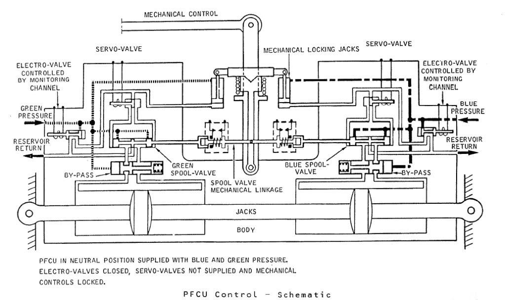
The diagram shows Green & Blue hydraulics supplied but the electro-valves (opened by the respective FBW channel) are both closed. You can see that the mechanical input lever is 'locked' to the PFCU input lever which will drive the SPOOL VALVE directly. When FBW is enabled, either the Blue or Green (never both together) ELECTRO-VALVE are signalled open, the ensuing hydraulic pressure then pushing the input clutch upwards and disengaging the mechanical input. FBW demands are now fed to the respective SERVO VALVE which will hydraulically send the SPOOL VALVE in the desired direction.
The Relay Jacks could be considered to be a little like a PFCU (you had 2 RJs per axix) but instead of the servo valves being driven by the FBW system they were driven by the autopilot and instead of driving a control surface, they drove the control runs. In manual flight the input spool was driven via a mechanical input lever, which would drive the RJ spool a little like Mech' signalling drove the PFCU spool. In A/P mode the mechanical input rod was de-clutched \xe0 la PFCU, but (and here's the clever part) this input was locked to the body of the Relay Jack which when it moved, drove the pilot's control in sympathy. (Control column, yoke or rudder pradals). As the respective control(s) was moved by the Relay Jack, the corresponding FBW position sensor (resolver) would change position and generate the FBW demand. (As the surface moved there was a feedback resolver at PFCU level).
As far as the FBW channels themselves went; there were 2 electronic signalling modes, Blue and Green, sub-divided into 3 groups (Inner Elevons, Outer & Mid Elevons and Rudders). Each group was independently monitored, and a fault in say the Rudder channel alone, would result in the rudders ONLY changing lanes. NOW ( ), The normal control channel was BLUE, and if this failed you would drop the respective channel into GREEN and if this failed you would drop into MECH. The selector switches (1 per group) enabled you to select BLUE/GREEN/MECH in that order. If for some reason you were selected to GREEN, a failure of that signalling lane would not drop you 'up' into BLUE, but into MECH. Your switch would only be in this position if you'd had a problem with BLUE, however you would select this on pushback while you were testing the flying controls, otherwise you spent your whole life selected to BLUE. As far as BA went, I can never remember a time personally when all 3 groups dropped from BLUE to MECH, but very rarely you might get a fault that caused a single group to briefly drop to MECH. Just about one of the very few common mode failures to each of the 3 groups would be a failure of the respective FBW static inverter. This thing, which was rightly monitored up to the hilt, produced a 26 Volt 1800 Hz output. (1800 Hz was chosen as this is not a harmonic of aircraft mainline 400 Hz AC supply)
Best regards
Dude
Hi again my friend. To further expand on CliveJ's superb explanation: Mechanical control inputs were fed to each of the 8 Powerd Flying Control Units (PFCUs), but in electronic signalling (either Blue or Green) these inputs were de-clutched at the PFCU input lever. When Fly By Wire' signalling is not available, the mechanical inputs (which as CliveL quite rightly points out) are driven by the Relay Jacks, now are locked to the input lever and can now move the input jack of the PFCU (known as the spool valve) and subsequently cause the PFCU to drive the control surface. (The body of the PFCU moved, the main jacks were attached at each end to structure and so obviously did not move). Hopefully this diagram will help visualising the process a little easier:
The diagram shows Green & Blue hydraulics supplied but the electro-valves (opened by the respective FBW channel) are both closed. You can see that the mechanical input lever is 'locked' to the PFCU input lever which will drive the SPOOL VALVE directly. When FBW is enabled, either the Blue or Green (never both together) ELECTRO-VALVE are signalled open, the ensuing hydraulic pressure then pushing the input clutch upwards and disengaging the mechanical input. FBW demands are now fed to the respective SERVO VALVE which will hydraulically send the SPOOL VALVE in the desired direction.
The Relay Jacks could be considered to be a little like a PFCU (you had 2 RJs per axix) but instead of the servo valves being driven by the FBW system they were driven by the autopilot and instead of driving a control surface, they drove the control runs. In manual flight the input spool was driven via a mechanical input lever, which would drive the RJ spool a little like Mech' signalling drove the PFCU spool. In A/P mode the mechanical input rod was de-clutched \xe0 la PFCU, but (and here's the clever part) this input was locked to the body of the Relay Jack which when it moved, drove the pilot's control in sympathy. (Control column, yoke or rudder pradals). As the respective control(s) was moved by the Relay Jack, the corresponding FBW position sensor (resolver) would change position and generate the FBW demand. (As the surface moved there was a feedback resolver at PFCU level).
As far as the FBW channels themselves went; there were 2 electronic signalling modes, Blue and Green, sub-divided into 3 groups (Inner Elevons, Outer & Mid Elevons and Rudders). Each group was independently monitored, and a fault in say the Rudder channel alone, would result in the rudders ONLY changing lanes. NOW ( ), The normal control channel was BLUE, and if this failed you would drop the respective channel into GREEN and if this failed you would drop into MECH. The selector switches (1 per group) enabled you to select BLUE/GREEN/MECH in that order. If for some reason you were selected to GREEN, a failure of that signalling lane would not drop you 'up' into BLUE, but into MECH. Your switch would only be in this position if you'd had a problem with BLUE, however you would select this on pushback while you were testing the flying controls, otherwise you spent your whole life selected to BLUE. As far as BA went, I can never remember a time personally when all 3 groups dropped from BLUE to MECH, but very rarely you might get a fault that caused a single group to briefly drop to MECH. Just about one of the very few common mode failures to each of the 3 groups would be a failure of the respective FBW static inverter. This thing, which was rightly monitored up to the hilt, produced a 26 Volt 1800 Hz output. (1800 Hz was chosen as this is not a harmonic of aircraft mainline 400 Hz AC supply)
Best regards
Dude
Last edited by M2dude; 16th Jan 2011 at 12:10 . Reason: Clarity; Oh for clarity
18th Jan 2011, 09:30
permalink Post: 1122
I so remember the BAe AST images from the 1980s, I always thought what a potentially nice looking aeroplane she was. I guess that vastly improving the L/D & T/W ratios could go quite a long way to improving the operating economics, but the noise issue was always going to be the crippler. (I know that they were looking at a 'leaky' version of the OLY593, ie. a very low bypass ratio, but this of course would still not really cut the mustard as far as noise goes). I guess there are no current takers then

Clive, you really surprise me when you say you don't think that composites would be used from a future SST, is there a material reason for this? (I'm curious because being of a simple avionic brain, I always assumed composites would be used. But if anyone knows this stuff, you certainly would Clive
).
To answer Mike-Bracknell's original query, as far as avionics goes we can really go to town. For her age Concorde had some truly amazing aircraft systems, for instance the flying controls. To enable mechanical control (both FBW channels failed) there was a highly complex and heavy mixing unit under the rear floor. (To mix pitch and roll pilot mechanical demands into differential elevon demand inputs). This of couse would have to be done away with, as well as the relay jacks and replaced with a pair of side-sticks. (See posts on previous page). A 2 crew operation would obviously be the way to go, but neither desirable or possible in my view when Concorde was designed.
A triplex or quadruplex flying control system (possibly even integrating autoflight) would replace the Concorde collection of several analog boxes with a very small handful of lightweight digital units.. The powerplant control will have major weight savings, just take a look at this lot. 8 Engine Control Units, 4 Bucket Control Units, 2 Nozzle Angle Scheduling Units, 4 Reheat Amplifiers, 8 AICUs, 4 Air Intake Sensor Units and a single Air Intake Test Unit could potentially be replaced by just 4 multi-channel EEC type units. (On subsonic aircraft the EECs are mounted on the engine itself, not sure if that's a good idea for an SST, given the operating environment. Air Data and Navigation systems take a major simplification and weight saving, the 3 INUs and 2 ADCs (All of them straight from the 'rent a hernia' store as far as weight goes), could be replaced by a single ADIRU and a SAARU. The fuel indication/management side of things (2 FQI packs, 2 level switching packs and 3 CG computers) would probably be replaced by a single Fuel Processing unit. Ahhhh perchance to dream
Best regards
Dude