22nd Aug 2010, 16:30
permalink Post: 70
Re Mach 2 ....
In the earliest days of the project, Concord(e) was described as a Mach 2.2 airliner.
Once the RR58 alloy arrived, and the first thermal fatigue tests were underway, Mach 2.2 appeared as somewhat optimistic, and to assure an acceptable airframe life, the Mmo (maximum operating Mach number) to be certified was brought down to Mach 2.04.
Interesting question just asked by somebody on another forum....
Why Mach 2.04 ? Why not Mach 2.10, or Mach 1.96 ?
With thermal fatigue still being a field that was only starting to be explored, was that a fully technical choice.... or was there a commercial aspect ?
Mach 1.96 would again have meant a few more hours life for the airframes, and would not really have made a significant difference in the flight duration.
But think of the huge difference between "more than twice the speed of sound" and "not quite as fast as twice the speed of sound".....
Mach 1.96 would simply not have "sold"......
I have no answer to the question who finally decided on '2.04', and I don't think many of the people that wrote the "TSS spec" are still with us, so we'll probably never know.
And along the very same lines, another snippet.....
In 1985, during a major cabin upgrade, BA installed the "Marilake" displays, that showed Mach, altitude, groundspeed, etc. in place of the simple Mach-only displays that Air France kept until the end.
Nice display, complete with microprocessors.... you must have seen photos.
Of course everybody wanted their photo taken next to the display saying "Mach 2".
So these display were subtly programmed to read "Mach 2.00" as soon as the Mach number was above 1.98, and they stayed there....even if the aircraft went to Mach 2.03 or beyond.
A tiny bit of cheating... but commercially it made a lot of sense, of course.
Like the earlier BA cabin displays, the Air France displays only showed the Mach number, and they were little more than "rescaled" digital voltmeters that directly displayed the 0-12V Mach signal from the Air Data Computer. They tended to flicker a bit from 2.00 to 2.01 to 2.02 and back, but at least they didn't "cheat". And I still proudly have a photo of myself with a "Concorde grin", at Mach 2.03 !
2nd Sep 2010, 23:55
permalink Post: 192
Hi canuck slf, Your incident was not the hydraulic contamination one, I'll describe that one in a minute or so below.
As far as your adventure goes, in the early days of Concorde operation there was an on-going issue of hydraulic seal failures. This led to the sort of thing that you described, where a major seal failure would occur, resulting in the loss of a main system. The standby Yellow system would be switched in to replace the failed one, and depending on the nature of the initial failure, could leak out of the same failed seal. (There were a couple of 'common areas', they were the intake spill door jack, and the Powered Flying Control Units; failures here could result in a double system fail). Your incident was almost certainly due to one of these cases. In the early 1990's the original Neoprene hydraulic seals were replaced with a new Viton GLT seal; this material had far superior age shrinking characteristics to Neoprene, and more or less cured the problem overnight. Eventually all the seals in each aircraft were replaced, and apart from a very few isolated cases, dual system losses were eliminated forever. Air France suffered a similar proportion of failures, however as their flying hours were a fraction of BA's, the effects were not as immediately apparent.
As far as far as the hydraulic contamination story goes, this happened in 1980 but involved one aircraft only, G-BOAG, but in it's original registration of G-BFKW. (having previously been on loan from British Aerospace, where it flew originally as a 'white tail' under this registration). The fragile nature of Concorde hydraulic fluid was not fully understood at this time, and as you say, a hydraulic drum dispenser had inadvertently been left exposed to the atmosphere, and had subsequently suffered water contamination, and this contaminated fluid had found it's way into G-BOAG. Now this hydraulic fluid, CHEVRON M2V has only two vices: One is that is extremely expensive, and the second is that it is highly susceptible to water contamination, EXTEMELY SO. If my memory serves me correctly, the maximum allowable level of water in the fluid is about 8ppm. (parts per million) and the fluid that was analysed after G-BOAG's problems was at about 30 ppm. The water deposits in the fluid gave the equivalent effect of 'rusting up' of critical hydraulic components. I was investigating an air intake control defect the previous day to the incident, but like everybody else had no idea that the real issue here was one of major systems contamination. We were all convinced that we had nailed the problem, only to find that the aircraft turned back on it's subsequent LHR-JFK sector with more serious problems, not only affecting the air intakes, but the artificial feel system also. It was now that we realised that there had to be a hydraulics problem here, and after fluid analysis, the awful truth was discovered. After this event, and the fragilities of M2V fluid were better understood, a strict regime of housekeeping was put in place in terms of fluid storage, and no such incidents with BA ever occurring again. The aircraft itself did not fly again for nine months, all components that were affected were removed from the aircraft and completely stripped and overhauled. Also all of the system hydraulic lines had to be completely purged, until there were no further traces of any contamination. After the aircraft was finally rectified, she successfully again returned to service with her new 'BA' registration of G-BOAG. However the following year, during a C Check, it was decided that due to spares shortages, and the closure of the LHR-BAH-SIN route, there just was not being enough work for seven aircraft, and therefore G-BOAG would be withdrawn from service. (In terms of spares, BA at the time for instance only had six sets of aircraft galleys, as aircraft went in for C checks the galley was 'robbed' to service the aircraft coming out of it's own C check). The aircraft was parked in a remote hangar, and was only visited when a component had to be 'robbed' for another Concorde, and the aircraft soon fell into disrepair, was filthy externally and became a really sad sight. Many people (not myself I might add) were adamant that G-BOAG would never fly again. However, in 1984 things had really started to improve for Concorde, with the charter business increasing and the LHR-JFK route in particular becoming a staggering success. It was decided that OAG would be returned to an airworthy condition. In 1985, with a fresh new interior, and with the new BA colour scheme, she was finally returned to service; and remained as one of the mainstays of the fleet right up to the end of Concorde services in October 2003. She now resides at the Boeing Museum of Flight in Seattle. (I have particularly fond memories of G-BOAG; in a previous post I mentioned flying through an electrical storm in late 1991 over Saudi Arabia, while returning from BKK-BAH to LHR. What I forgot to mention was the spectacle of DOZENS of fierce fires burning on the ground, towards our starboard horizon. These were Sadams oil fires, still burning in Kuwait. It made a sombre contrast to the amazing electrical spectacle right in front of us).
As far as low speed flying control activity was concerned, this was a combination of the fairly flexible outer wing sections, being buffeted by low speed turbulence (the wing tip tanks 5A & 7A also being empty), as well as some autostab inputs. This was perfectly normal, and part of the design our aircraft. However the development aircraft had even more flexible outer wing sections, which used to almost straighten up in high speed flight. However due to fatigue concerns, external lateral stiffeners were added to the underside of the wings during production of the airline aircraft. (these can be easily seen from underneath the wings, just outboard of the nacelles). Unfortunately these external stiffeners also resulted in over a one tonne fuel penalty to the production aircraft, due to increased weight, as well as higher drag in a critical part of the wing aerodynamic surface.
Dude
Last edited by M2dude; 3rd Sep 2010 at 00:07 .
6th Sep 2010, 17:13
permalink Post: 233
Nick:
The top of the boundary is FL600, largely an artificial number - the airframe is good for rather higher than this, but I believe air supply and ramp scheduling could become an issue not so far above this level.
Mmo - ditto. As others have said, Mmo was originally going to be higher (M2.2) but was reduced to extend fatigue life as the aircraft design 'grew'.
The significance of the shaded 59% portion of the graph is that it shows the envelope at that CG - in this case the relevant line is the bottom of the shaded area - M1.56. This is the MINIMUM mach number that can be flown with the CG at 59% (normal for supersonic cruise). You will see it represented on the Machmeter (a few pages back) as the "AFT" bug. i.e. you can't fly slower than this without moving the CG forward.
So it can be seen that the decel must be done in concert with CG transfer - and as (mostly) always the designers had made it as straightforward as possible. Transferring forward from Tank 11 using the two electric pumps the rate of txfr pretty well matched the standard decel profile, leaving the FE to make the occasional tweak to keep the flight envelope in concert with the CG envelope through the decel/descent.
In the case of abnormal procedures depriving one of electrical power then some other way had to be found to enable a descent (which required a decel) and that is why there are also two hydraulically driven fuel transfer pumps in tank 11.
It's a bit confusing at first, but there are two overlapping flight envelopes - the speeds/alts drawn on the basic envelope and those determined by the CG postion at the time.
In practice - one had a takeoff CG, a landing CG, a subsonic crz CG, a supersonic cruise CG and the only area one had to keep a close eye on was the transition between the last two. There were several visual and aural warnings to back up the CG and Machmeter bugs.
Quote:
| So is the Cof G of 59% the determining factor for the MMO or is it some other factor? |
Mmo - ditto. As others have said, Mmo was originally going to be higher (M2.2) but was reduced to extend fatigue life as the aircraft design 'grew'.
The significance of the shaded 59% portion of the graph is that it shows the envelope at that CG - in this case the relevant line is the bottom of the shaded area - M1.56. This is the MINIMUM mach number that can be flown with the CG at 59% (normal for supersonic cruise). You will see it represented on the Machmeter (a few pages back) as the "AFT" bug. i.e. you can't fly slower than this without moving the CG forward.
So it can be seen that the decel must be done in concert with CG transfer - and as (mostly) always the designers had made it as straightforward as possible. Transferring forward from Tank 11 using the two electric pumps the rate of txfr pretty well matched the standard decel profile, leaving the FE to make the occasional tweak to keep the flight envelope in concert with the CG envelope through the decel/descent.
In the case of abnormal procedures depriving one of electrical power then some other way had to be found to enable a descent (which required a decel) and that is why there are also two hydraulically driven fuel transfer pumps in tank 11.
It's a bit confusing at first, but there are two overlapping flight envelopes - the speeds/alts drawn on the basic envelope and those determined by the CG postion at the time.
In practice - one had a takeoff CG, a landing CG, a subsonic crz CG, a supersonic cruise CG and the only area one had to keep a close eye on was the transition between the last two. There were several visual and aural warnings to back up the CG and Machmeter bugs.
16th Sep 2010, 08:35
permalink Post: 370
BlueConcorde
As far as the MEPU went, yes there was just mainly empty space inside the tailcone, Aside from the tail wheel assembly there was just the power supply for the tail beacon as well as the fuel vent and jettison pipes. (On the forward bulkhead there were pumps and valves for tank 11). Having this great empty void did create problems in the early days of airline operation; there were some internal structural failures inside the tailcone (a low stressed area, so it was never serious). These failures were quickly attributed to acoustic fatigue inside the tailcone, due to resonance with engine and aerodynamic noise. This never occurred during any of the development flying; the prototypes and aircraft 1010 had a far smaller tailcone anyway, and aircraft 102, 201 and 202 had the bulk of the MEPU assembly complete with Hydrazine tank to fill up most of the void. The fix to the cracking problems was both very simple and quick to implement, and it never became a big deal. The MEPU, as has been mentioned a few times previous, was both useless and unsafe as far as a commercial aircraft goes; being replaced by a ram air turbine.
It's funny, but this is how this wonderful thread started over one month ago by stilton , I for one am so glad that it has both progressed and diversified the way that it has.
As far as charters go I'll leave it up to EXWOK or one of the other guys to answer, as far as flight planning goes. Thanks for your comments BlueConcorde, they always took a ground engineer on RTW charters, and although I never had the pleasure of directly participating in one (although I was on the end of a phone several times when problems occurred en-route)I WAS due to go in 2000, but tragic events in Paris caused that charter to be cancelled. I was however lucky enough to participate in various other charters, my most memorable one was in October 1991, when the World Bank chartered Concorde to Bangkok. The most amazing thing about RTW charters (or earth orbiters, as I would call them) was that the aircraft often returned to London with only a very small handfull of minor defects. The thing about Concorde was the more that she flew, the happier she was, and less likely to catch a cold.
PS. oops, EXWOK is already 'there'
Dude
23rd Sep 2010, 02:10
permalink Post: 450
That's why those two small planks on Concorde work so well.
Quite a common trick of the trade eg with fighters eg the leading edge extension (LEX - the narrow aspect delta at the front of the wing) on the F18 and others. There are plenty of pix around with the vortex made visual due humidity and it can be seen to be tight, curly and designed nicely to interact with the fins - which, for the F18 has caused much in the way of fatigue related grey hairs in the boffin fraternity.
and especially it's used in moving the CofG.
again, a common observation eg 747-400 tail tanks .. just a matter of how much the movement is required to be.
16th Oct 2010, 22:27
permalink Post: 580
OK, I see others have already posted answers.
I've carefully avoided looking at them, but I'll might as well plug in mine now.
My personal problem is that I was involved in the very earliest days, before the aircraft went into service, and then in the last days and afterwards...
So the questions dealing with the in-service period are totally outside my field of experience... all I can do is guess, in case I saw the answers somewhere.
1) How many Concorde airframes were built?
Twenty-two.
Two static-test airframes.
- One at Toulouse, for purely static tests, and tests such as vibration and flutter.
- One at Farnborough, for the long-duration thermal fatigue tests.
(A few bits and pieces of the Farnborough test specimen have survived, and can still be seen at the Brooklands museum).
Two prototypes (001 and 002)
Two pre-production aircraft (01 and 02)
Two production aircraft used for certification, that never entered service (201 - F-WTSB and 202 - G-BBDG)
Fourteen production aircraft, seven that served with British Airways, seven that served with Air France.
2) As far as the British constructed aircraft went, name the destinations that were served?. Regular flight numbers only, excludes charters etc.
Not a clue as to the full list.
- Bahrain, obviously.
- JFK.
- IAD (not sure if that's rated as regular, or only incidental)
- Dallas (with Braniff)
- Barbados (of course, right until the end)
- Sngapore (with Singapore Airlines, and G-BOAD in Singapore Airlines colours on one side)
- Sydney (again no idea if that rated as a regular flight or only a few tries)
3) What was the departure time for the ORIGINAL morning LHR-JFK Concorde services? (Not called the BA001 then either).
Not a clue either. Vague memory of about 10:00 am which gave you a full working day in New York.
4) Further to question 3 above, what WERE the original flight numbers for the BA001 and BA003? (The morning and evening LHR-JFK services?)..
Never flew on them, never had to deal with them.
BA174 comes to mind from the depths of my memory, in that case BA003 would have been BA176?
5) There were no less than FORTY SIX fuel pumps on Concorde. What was the breakdown for these? (Clue; don't forget the scavenge pump )
M2dude, I did AFCS, not the fuel system. I believe you, but without pulling out some diagrams I honestly have NO idea.
I expect each tank had at least two pumps, which gets me up to 26.
Then there were a few emergency pumps for the trim tanks, and I suppose each engine had additional pumps associated with it.
Still nowhere near the 46 I need to find.....
6) What airframe had the only TOTALLY unique shape?
That would have been my old friend, 01 (G-AXDN), first pre-production aircraft, now at Duxford.
It was the first Concorde with the new transparent visor, but it still had the short tail that characterised the prototypes.
It was 02 (F-WTSA), the first French pre-production aircraft, that was close to the final shape of the production aircraft.
7) This one is particularly aimed at ChristiaanJ. What was the total number of gyros on the aircraft?
Good question.... never counted them all. But I'll try a guess.
First a nice one, the SFENA Emergency Standby Artificial Horizon (made by the firm I worked for).
Ran off the Emergency Battery Bus via a small independent inverter.
And if that failed too, it would still run reliably for several minutes on its own inertia.
Next, the rate gyros used by the autostabilisation system ; these measured the angular rate of the aircraft along the three main axes, pitch, roll and yaw.
There were six, three each for the two autostab systems.
Now the rest....
Each IMU (inertial measurement unit, part of the inertial naviagation system) had three gyros.
With three INS on board, that would make nine.
Much as I try, I can't remember other ones, so I'll look forward to the final answer.
I can imagine the weather radar using an additional gyro for stabilisation, but I never went there.
8) How many wheel brakes?
Unless this is a trick question, I would say eight, for each of the main gear wheels.
The nose gear did not have any brakes - unless there were some small ones to stop the wheels rotating after retraction of the gear, but not used during landing.
9) What Mach number was automatic engine variable intake control enabled?
No idea.
Mach 1.0 or thereabouts is my personal guess only.
10) Above each bank of engine instruments were three lights, a blue, a green and an amber. What did they each signify?
I know that they each monitored the status of one of the engines, because it was too complex for the pilots to fully monitor all the parameters of all four engines in the short time between start-of-roll and V1... they had too many other things to do.
But I don't remember what each light meant, would have to look it up in the manual.
11) At what airfied were the first BA crew base training details held?
No idea.
Was it Brize Norton, or Casablanca?
12) What LHR runways did Concorde use for landing and take-off? (Trick question, not as obvious as it might seem).
No idea.
Vague memory of it being systematically the North runway for noise issues.
13) What operator had serious plans to operate Concorde from SNN to JFK in the early 1980's?
No idea.
14) What development aircraft did not exceed Mach 2 until fifteen months after her maiden flight?
I would expect the obvious answer to be 002.
Working up from first flight to Mach 2 was a slow and laborious process, and in the end it was 001 that both flew first, and also went to Mach 2 first.
I don't think any of the other aircraft took that long.
A I said, I tried to answer all questions "off the top of my head", without looking at any other sources.
CJ
I've carefully avoided looking at them, but I'll might as well plug in mine now.
Quote:
|
Originally Posted by
M2dude
If you were never personally involved withe the aircraft you can leave out the really stinky questions if you want.
|
So the questions dealing with the in-service period are totally outside my field of experience... all I can do is guess, in case I saw the answers somewhere.
1) How many Concorde airframes were built?
Twenty-two.
Two static-test airframes.
- One at Toulouse, for purely static tests, and tests such as vibration and flutter.
- One at Farnborough, for the long-duration thermal fatigue tests.
(A few bits and pieces of the Farnborough test specimen have survived, and can still be seen at the Brooklands museum).
Two prototypes (001 and 002)
Two pre-production aircraft (01 and 02)
Two production aircraft used for certification, that never entered service (201 - F-WTSB and 202 - G-BBDG)
Fourteen production aircraft, seven that served with British Airways, seven that served with Air France.
2) As far as the British constructed aircraft went, name the destinations that were served?. Regular flight numbers only, excludes charters etc.
Not a clue as to the full list.
- Bahrain, obviously.
- JFK.
- IAD (not sure if that's rated as regular, or only incidental)
- Dallas (with Braniff)
- Barbados (of course, right until the end)
- Sngapore (with Singapore Airlines, and G-BOAD in Singapore Airlines colours on one side)
- Sydney (again no idea if that rated as a regular flight or only a few tries)
3) What was the departure time for the ORIGINAL morning LHR-JFK Concorde services? (Not called the BA001 then either).
Not a clue either. Vague memory of about 10:00 am which gave you a full working day in New York.
4) Further to question 3 above, what WERE the original flight numbers for the BA001 and BA003? (The morning and evening LHR-JFK services?)..
Never flew on them, never had to deal with them.
BA174 comes to mind from the depths of my memory, in that case BA003 would have been BA176?
5) There were no less than FORTY SIX fuel pumps on Concorde. What was the breakdown for these? (Clue; don't forget the scavenge pump )
M2dude, I did AFCS, not the fuel system. I believe you, but without pulling out some diagrams I honestly have NO idea.
I expect each tank had at least two pumps, which gets me up to 26.
Then there were a few emergency pumps for the trim tanks, and I suppose each engine had additional pumps associated with it.
Still nowhere near the 46 I need to find.....
6) What airframe had the only TOTALLY unique shape?
That would have been my old friend, 01 (G-AXDN), first pre-production aircraft, now at Duxford.
It was the first Concorde with the new transparent visor, but it still had the short tail that characterised the prototypes.
It was 02 (F-WTSA), the first French pre-production aircraft, that was close to the final shape of the production aircraft.
7) This one is particularly aimed at ChristiaanJ. What was the total number of gyros on the aircraft?
Good question.... never counted them all. But I'll try a guess.
First a nice one, the SFENA Emergency Standby Artificial Horizon (made by the firm I worked for).
Ran off the Emergency Battery Bus via a small independent inverter.
And if that failed too, it would still run reliably for several minutes on its own inertia.
Next, the rate gyros used by the autostabilisation system ; these measured the angular rate of the aircraft along the three main axes, pitch, roll and yaw.
There were six, three each for the two autostab systems.
Now the rest....
Each IMU (inertial measurement unit, part of the inertial naviagation system) had three gyros.
With three INS on board, that would make nine.
Much as I try, I can't remember other ones, so I'll look forward to the final answer.
I can imagine the weather radar using an additional gyro for stabilisation, but I never went there.
8) How many wheel brakes?
Unless this is a trick question, I would say eight, for each of the main gear wheels.
The nose gear did not have any brakes - unless there were some small ones to stop the wheels rotating after retraction of the gear, but not used during landing.
9) What Mach number was automatic engine variable intake control enabled?
No idea.
Mach 1.0 or thereabouts is my personal guess only.
10) Above each bank of engine instruments were three lights, a blue, a green and an amber. What did they each signify?
I know that they each monitored the status of one of the engines, because it was too complex for the pilots to fully monitor all the parameters of all four engines in the short time between start-of-roll and V1... they had too many other things to do.
But I don't remember what each light meant, would have to look it up in the manual.
11) At what airfied were the first BA crew base training details held?
No idea.
Was it Brize Norton, or Casablanca?
12) What LHR runways did Concorde use for landing and take-off? (Trick question, not as obvious as it might seem).
No idea.
Vague memory of it being systematically the North runway for noise issues.
13) What operator had serious plans to operate Concorde from SNN to JFK in the early 1980's?
No idea.
14) What development aircraft did not exceed Mach 2 until fifteen months after her maiden flight?
I would expect the obvious answer to be 002.
Working up from first flight to Mach 2 was a slow and laborious process, and in the end it was 001 that both flew first, and also went to Mach 2 first.
I don't think any of the other aircraft took that long.
A I said, I tried to answer all questions "off the top of my head", without looking at any other sources.
CJ
22nd Oct 2010, 09:26
permalink Post: 597
OK guys, here are the answers. If you disagree about any of them then fire away, the old memory certainly 'aint perfect.

As many of you have guessed, there were 22: The 14 production airframes, the 2 production series development aircraft (201 & 202), the 2 pre-production airframes (101 & 102) and the 2 prototypes 001 & 002. PLUS, the major fatigue test specimen at the RAE Farnborough and the static test specimen at CEAT in Toulouse. The CEAT tests actually tested the wing to destruction; I seem to remember it was something like a 200% overload before the wing failed at the root. And great but rather sad pictures
VOLUME
, never seen these before.
OK, from MY memory
 , we have: London LHR (duhhh!!), Bahrein BAH, Singapore SIN, New York JFK, Washington IAD, Dallas DFW, Miami MIA, Toronto YYZ, Barbados BGI, and Riyadh RUH. As well as charters being ommited, so are some of the special 'surprise' shuttle appearances that Concorde would make, substituting a subsonic to and from destinations such as Manchester and Edinburgh.
11:15
The BA193 and BA 195.
OK, there were 12 engine feed pumps (3 per engine) 8 main transfer tank pumps (2 each for the transfer tanks 5, 6, 7 & 8), 4 'A' tank pumps (2 each for 5A & 7A), 8 trim-transfer tank pumps (2 electric pumps each for tanks 9, 10 & 11 PLUS 2 hydraulically driven pumps for tank 9), 4 electric engine start pumps (there was a single electric start pump per engine that delivered fuel to it's own dedicated start atomiser in the combustion chamber. The pump automatically ran when the engine HP valve was set to OPEN and would continue running for 30 seconds after the DEBOW switch was returned to the 'normal' position), 4 engine first stage pumps (a single mechanically driven pump per engine), 4 second stage pumps (a single pneumatically driven pump, sometimes termed 'the turbopump, per engine. This would cut out at around 20,000'), our scavenge tank pump (triggered automatically when there was 7 US gallons in the tank; pumping it back into tank 2. This pump was identical to an 'A' tank transfer pump), and FINALLY, a single de-air pump for tank 10. The pump would drive the fuel through a mesh, removing air bubbles from the fuel. Tank 11 used the L/H trim pump for de-air (similar principle)and would be switched on during take-off. This is why the tank 5 trim inlet valve being set to over-ride OPEN would result in the tank being highly pressurised in the case of the Gonesse disaster; the pump would obviously pressurise the L/H trim gallery and any tank on that side with an open inlet valve!!!
G-AXDN, aircraft 101. (A production wing, fuselage, droop nose and intakes, but with the short tail section and secondary nozzles of the prototypes.
Ready ChristiaanJ? There were 18....Yes, the single SFENA standby horizon, 9 INS gyros (one per X,Y and Z platform in each of the 3 INUs), 8 autostab' rate gyros (one per axis for each of the 2 autostab' computers PLUS a monitor gyro for the pitch axis). The radar by the way used attitude signals from the INS.
9. One per main wheel plus the single 'in flight braking' nose wheel brake.
Mach 0.7!!! Between this and Mach 1.26 the intake surfaces were positioned as a function of engine N1 if the engine was shut down for any reason. (Otherwise of course the intake surfaces were fully up). You needed a sub idle N1 of 57% and below for all this to happen, and it was to assist relight performance and reduce buffet. Between Mach 1.26 and 1.32 the ramps were driven down slightly to about 5%, full supersonic scheduling itself commencing at Mach 1.32.
Already brilliantly answered by Brit312 (as well as the FSLabs diagram). Yep, Geen GO, T/O monitor armed, fuel flow and P7 at or above datum, A/C on ground, reverse not selected and CON light not on. Amber CON (Reheat selected and not detected, N1 OK or reverse selected and primary nozzle (Aj) not at minimum. Blue REV; steady buckets at reverse, flashing buckets in transit.
Fairford, followed by Brize Norton, and then a host of airfields from Prestwick and Shannon to Chateauroux.
OK, probably no surprises now:
Landing - 27L & R, 9L & R (prior to LHR mag' deviation update were 28L & R & 10L & R) together with 23/05.
Take off - 27L (28L), 9R (10R) and 9L. (10L never happened as take offs on this runway only occurred in 2003).
It was FedEx, they planned to operate two stripped out aircraft, leased from BA, between Shannon and JFK as high value parcel carriers. The idea was that parcels would be flown in from all over Europe by small FedEx feeder aircraft and the parcels transferred to Concorde which would then speed on to JFK in around 2 1/2 hours. It never happened because of a combination of economics appraisal by FedEx and BA deciding that it could would not release the aircraft anyway.
A/C 101, G-AXDN first flew on 17th December 1971 with FIXED INTAKES!! (101 was going to be the launch vehicle for the new digital intake control system, but the 'boxes' were still being designed). This placed an operating limit of Mach 1.5 on the aircraft, limiting her ability with such a restricted flight envelope. She returned to Filton in late 1972 for installation of the system, as well as the new Olympus 593-602 engine. (The engine, very similar to the production Mk 610 version, used a quite revolutionary annular combustion chamber, and eliminated at a stroke the thick smoke exhaust that had up to then been Concorde's unwanted visual signiture). The aircraft flew more or less smokeless on 15 March 1973, achieving Mach 2 soon afterwards. As ChristiaanJ pointed out, the British prototype 002 had a similar gap, actually significantly higher, of 19 months. (The French aircraft 001 had an even longer gap of some 20 months).
I hope you guys had fun with this one, regards to all
Dude
Quote:
| 1) How many Concorde airframes were built? |
Quote:
| 2) As far as the British constructed aircraft went, name the destinations that were served?. Regular flight numbers only, excludes charters etc. |
, we have: London LHR (duhhh!!), Bahrein BAH, Singapore SIN, New York JFK, Washington IAD, Dallas DFW, Miami MIA, Toronto YYZ, Barbados BGI, and Riyadh RUH. As well as charters being ommited, so are some of the special 'surprise' shuttle appearances that Concorde would make, substituting a subsonic to and from destinations such as Manchester and Edinburgh.
Quote:
| 3) What was the departure time for the ORIGINAL morning LHR-JFK Concorde services? (Not called the BA001 then either). |
Quote:
| 4) Further to question 3 above, what WERE the original flight numbers for the BA001 and BA003? (The morning and evening LHR-JFK services?). |
Quote:
5) There were no less than FORTY SIX fuel pumps on Concorde. What was the breakdown for these? (Clue; don't forget the scavenge pump
 ).
).
|
Quote:
| 6) What was the only development airframe to have a TOTALLY unique shape? |
Quote:
| 7) This one is particularly aimed at ChristiaanJ. What was the total number of gyros on the aircraft? |
Quote:
| 8) How many wheel brakes? |
Quote:
| 9) What Mach number was automatic engine variable intake control enabled? |
Quote:
| 10) Above each bank of engine instruments were three lights, a blue, a green and an amber. What did they each signify? |
Quote:
| 11) At what airfield were the first BA crew base training details held? |
Quote:
| 12) What LHR runways did Concorde use for landing and take-off? (Trick question, not as obvious as it might seem). |
Landing - 27L & R, 9L & R (prior to LHR mag' deviation update were 28L & R & 10L & R) together with 23/05.
Take off - 27L (28L), 9R (10R) and 9L. (10L never happened as take offs on this runway only occurred in 2003).
Quote:
| 13) What operator had serious plans to operate Concorde from SNN to JFK in the early 1980's? |
Quote:
| 14) What development aircraft did not exceed Mach 2 until fifteen months after her maiden flight? |
I hope you guys had fun with this one, regards to all
Dude
Last edited by M2dude; 22nd Oct 2010 at 11:21 . Reason: oops, misssed out question 2
24th Dec 2010, 17:56
permalink Post: 997
[xxxxquote=Mike Bracknell]
Trust me, i'm definitely just here for the ride (so to speak) and quickly defer to you and the others who definitely know! Mike Bracknell[xxxx/quote]
Hell Mike, I meant I should leave it for others who definitely know, not you!
[xxxxquote]A little p.s. from me - having looked at Clive's diagram on this page showing the bathtubs, aren't the strengtheners the oval cups outboard of the main fixings on the page? with one pointed to by the words "Bottom machined skin panel"?
This looks like it's another layer of shear in order to fulfil the brief of working around the reported skin problems in that area. Just strange it had to break the surface like that? [xxxx/quote]
I don't think so Mike, there are far too many of them. It looks more like 'pocketing' of the machined skin to reduce weight; and incidentally that SA overdid it, since there were clearly cracks developing along the spanwise joints between the various wing sections.
Incidentally, doesn't that picture show ever so clearly why designing and fitting that postGonesse Kevlar liner to the lower skins was such a difficult job!
[xxxxquote=ChristiaanJ]If so, they are indeed shown in the structural repair manual and listed as 'doublers'. There are ten of those, from spar 62 to spar 71.
Reading "between the lines", the modification dates from about 1978, and was applied by successive service bulletins to both the BA and AF aircraft. [xxxx/quote]
Yes, I agree, they look like skin doublers put on as a repair job, and that makes (to me) a lot more sense than additions to increase outer wing stiffness. What has confused me from the beginning was that I equated "outer wing stiffness" with "outer wing torsional stiffness" because I could see why somebody might want to increase that but I couldn't, and can't, see why anyone would want to increase outer wing bending stiffness - if you get a little more dihedral who cares? But additional material to increase or recover fatigue life is another matter altogether.
Why external? Just look at that drawing - where could you add additional bending material easily?
[xxxxquote=Landroger]Digital control is a hell of a lot easier than Analogue - in my humble opinion.[xxxx/quote]
Depends when you were born Roger. Now if you came into this world before WW2 ......
[xxxxquote=Mr Vortex]I'm was wondering that, according to the manual and some document said that the vortex lift start to form on wing tip first. Why's that happened? Why not the root of the wing first?
Is it cause by the local wing tip vortex push the air causing more upwash
and hence more effective AoA causing it to reach the stall AoA first is that right?
Also, does the wing vortex on the Concorde has an influence or the effect on
the rudder? [xxxx/quote]
Ah! this gets a little complicated. Every lifting wing generates a pair of vortices at the tip, but these are not the vortices most people associate with Concorde. The massive vortices you see when the air is moist and the water vapour condenses out because of the drop in air pressure inside the vortex start, as you suggest at the wing root from that highly swept leading edge. The wingtip vortices are still there, even when the main vortices are doing their stuff, so Concorde actually has two sets of vortices acting on the upper surface, although this is not obvious to the casual observer.
Simply, the wing vortex has no effect on the rudder.
But whilst I am writing about vortices, can I digress to talk about the 'moustaches' aka GT6. Somebody, I forget who, asked about their use for controlling longitudinal stability and somebody else replied, quite correctly, that they were a contribution to lateral stability. What was happening without them was that high AoA (by which I mean in excess of about 10~12 degrees) the 'crossflow' on the front fuselage generated a pair of small vortices which, in sideslip, wandered across the base of the fin. This gave some sidewash that cancelled the 'incidence' coming from the sideslip itself so that the bottom of the fin was effectively operating at zero slip and therefore zero lift. Result - the weathercock stability dropped to virtually zero for small sideslip angles. The small vortex generators (Generator Turbillon or GT) had the effect of fixing the location of the origin of the forebody vortices so that they didn't wander - in fact they tended to become entrained into the main wing vortices - problem solved.
Now if I can sort it out I will try to upload some pretty pictures showing those two sets of wing vortices.
CliveL
25th Dec 2010, 22:37
permalink Post: 1007
Quote:
|
Originally Posted by
Mike-Bracknell

We all know Concorde went at Mach 2 at FL600, but were there instances (for the press, certification, etc) that you went supersonic considerably closer to the deck? and what issues (if any) did that bring up?
|
Flight envelope
Those are the official certified limits.
I doubt somehow anybody went beyond those "for the press".....
But during certification, yes, each of those limits was exceeded, slowly and carefully, to be able to draw those official operational limits on the document.
For instance, the certified Mmo is 2.04. During certification, G-BBDG (202) went to Mach 2.21....
Even while staying within the limits, she could could exceed Mach 1 just below 30,000 ft.
Also, during the acceptance flights after major overhauls, most of those envelope limits would be exceeded by a given margin, to prove the aircraft still met all the certification requirements. Whether any of that was done 'closer to the deck', I wouldn't know.
The 'issues' would vary. Performance would be one issue... Delta Golf (and 01, who went to Mach 2.23) basically "ran out of steam" at that speed.
Another issue would be that 'going beyond the borders' shortened the fatigue life of the airframe, and it was difficult to assess exactly by how much. It was one of the reasons why Delta Golf and Sierra Bravo (the certification aircraft) in the end never went into service.
CJ
27th Dec 2010, 14:04
permalink Post: 1026
A pot pourri of responses after my Christmas reading!
This actually is interesting in that the n umbers show one of the fundamental features that made the Ol 593 such a good choice. If you look closely at the TO and cruise values you will find that at TO the overall compressor pressure ratio is 13.5 the compressor exit temperature 460 degC and the turbine inlet temperaure is 1152 degC. In cruise the pressure ratio is 10.5, the compressor exit is 565 degC and the TET 1100 degC.
Somebody, I can't find the exact post, was asking whether the elevated cruise total temperatures affected engine life, and here we see why this is so. As Christian said in another posting, when you compress air it gets hotter - from 21 degC to 460 degC at take off and from 127 degC to 565 degC in cruise. A fundamental limit on engine operation is the turbine entry temperature. Not only does it affect the maximum TO thrust you can get but also the continued exposure to cruise TETs has a very big effect on engine fatigue life, and engine manufacturers have shown extremes of ingenuity when developing new materials and ways of cooling the blades to increase allowable TET.
The problem with supersonic operations is that you start from an elevated intake delivery temperature so that when the flow exits the compressor it is already very hot 565 instead of 460 to be exact. But the maximum temperature one can stand for fatigue reasons is limited, therefore the amount of fuel you can pour in must be limited also, and the thrust you can develop per pound of airflow is roughly proportional to the fuel input/temperature rise. To get any sensible cruise thrust then one must squeeze the cruise TET as high as you dare for fatigue reasons but also you need to keep the compression ratio down so that the temperature going into the combustion chambers is as low as you can get away with. This tend to drive engines designed for extended supersonic operations to having a low pressure ratio. This is against the trend in subsonic operations where compression ratios have been steadily increasing along with bypass ratios.
The net result then is that the engine must be designed with a low OPR and must operate with cruise TET much closer to its TO TET value than would be necessary, or indeed desirable, on a subsonic design.
Actually, here, as on some other apparent carry-overs, one should look at the equipment supplier rather than the aircraft manufacturer to trace continuity. Here we have Messier supplying Concorde's gear and Dowty (OK they are now part of Messier) supplying the A330. And having worked on both, I seem to remember that the means of doing the shortening are quite different.
Yes, they both came out of the Bristol drawing office. One minor anecdote: the 'ramshorn' stick was a novelty to the Concorde flight test crews but they got to like it, or at least put up with it. All went well until it came to the time when Dave Davies, the ARB Chief Test Pilot, came to put his rubber stamp on the aircraft.
Concorde's seats, just like those on your car, could be moved back and fore to get your legs on the pedals and up and down so you could see over the bonnet (sorry, instrument panel). The control column of course stayed in one place, so the relationship of the 'horns' to ones thighs varied with ones height. Andre Turcat was about 6ft 2in, Trubbie and the others of average height. The smallest regular pilot was Jean Franchi at, I suppose, about 5ft 7 or 5ft 8. No problems. But Dave Davies was short like me and he found that he could not get full back stick and full aileron because the ramshorn fouled his thighs.
Consternation! Completely unacceptable! I don't know what arguments they used to convince him it was all OK really, but it got through certification. I would certainly be interested to learn from the pilots in this group as to whether it was ever a problem.
I can't resist this one!. Has anyone ever noticed/wondered about the tiny bit of the outer elevon that has been chopped off? That was my first real input into the design as a young erk looking at variability of touchdown conditions and coming to the conclusion that if the pilot got into trouble and was trying to pick up a trailing wing with too much AoA as well then he was likely to hit the ground with the downgoing elevon. I persuaded my boss that this was so and we made a small adjustment.
In self defence I am going to plead that this was well before the days of the Type 28 nozzle, so the issue of buckets contacting the ground first never came up!
To the point where an American Airline maintainance engineer, watching a prototype taking off and with full benefit of being located strategically for maximum sideline noise, remarked on what he described as 'visible acoustic radiation'
On another occasion, it was reputed that Stanley Hooker, watching a TO in the company of HRH the Duke of Edinburgh, remarked that "You know Sir that that noise represents less energy than it takes to boil an egg". to which he got the reply "Then I must congratulate you Sir Stanley, on producing so much noise for the expenditure of so little energy".
There was an effect and in consequence the aircraft performance brochures were formally calculated for north/south flight. Pity really, it would sometimes have been nice to be able to fly guarantee performance demonstrations in the most favourable direction
That's enough for today!
CliveL
Quote:
|
Originally Posted by
M2Dude
I hope this one is interesting; it's a Rolls Royce diagram illustrating what the wildly varying differences were in terms of the engine between take off and supersonic cruise. The primary nozzle can be seen at the rear of the engine, together with the reheat assembly and the secondary nozzle (reverser buckets).
|
This actually is interesting in that the n umbers show one of the fundamental features that made the Ol 593 such a good choice. If you look closely at the TO and cruise values you will find that at TO the overall compressor pressure ratio is 13.5 the compressor exit temperature 460 degC and the turbine inlet temperaure is 1152 degC. In cruise the pressure ratio is 10.5, the compressor exit is 565 degC and the TET 1100 degC.
Somebody, I can't find the exact post, was asking whether the elevated cruise total temperatures affected engine life, and here we see why this is so. As Christian said in another posting, when you compress air it gets hotter - from 21 degC to 460 degC at take off and from 127 degC to 565 degC in cruise. A fundamental limit on engine operation is the turbine entry temperature. Not only does it affect the maximum TO thrust you can get but also the continued exposure to cruise TETs has a very big effect on engine fatigue life, and engine manufacturers have shown extremes of ingenuity when developing new materials and ways of cooling the blades to increase allowable TET.
The problem with supersonic operations is that you start from an elevated intake delivery temperature so that when the flow exits the compressor it is already very hot 565 instead of 460 to be exact. But the maximum temperature one can stand for fatigue reasons is limited, therefore the amount of fuel you can pour in must be limited also, and the thrust you can develop per pound of airflow is roughly proportional to the fuel input/temperature rise. To get any sensible cruise thrust then one must squeeze the cruise TET as high as you dare for fatigue reasons but also you need to keep the compression ratio down so that the temperature going into the combustion chambers is as low as you can get away with. This tend to drive engines designed for extended supersonic operations to having a low pressure ratio. This is against the trend in subsonic operations where compression ratios have been steadily increasing along with bypass ratios.
The net result then is that the engine must be designed with a low OPR and must operate with cruise TET much closer to its TO TET value than would be necessary, or indeed desirable, on a subsonic design.
Quote:
|
I
s this another item that Airbus used for the A330/340? I can't remember the exact arrangement for Concorde, but the 330 uses a clever lever arrangement at the top of the leg.
I was not even aware of this A33/340 similarity, sounds yet another case of Airbus using Concorde technology. (Immitation still is the greatest form of flattery I guess). As far as I am aware Concorde had none of the lubrication issues that you describe. M2Dude |
Actually, here, as on some other apparent carry-overs, one should look at the equipment supplier rather than the aircraft manufacturer to trace continuity. Here we have Messier supplying Concorde's gear and Dowty (OK they are now part of Messier) supplying the A330. And having worked on both, I seem to remember that the means of doing the shortening are quite different.
Quote:
|
Originally Posted by
Brit312
The Britannia and now you are talking about the love of my life and yes I do remember the story of the nose and visor selector, but we have forgotten the most obvious. Where do you think they got the idea for the control column from
|
Yes, they both came out of the Bristol drawing office. One minor anecdote: the 'ramshorn' stick was a novelty to the Concorde flight test crews but they got to like it, or at least put up with it. All went well until it came to the time when Dave Davies, the ARB Chief Test Pilot, came to put his rubber stamp on the aircraft.
Concorde's seats, just like those on your car, could be moved back and fore to get your legs on the pedals and up and down so you could see over the bonnet (sorry, instrument panel). The control column of course stayed in one place, so the relationship of the 'horns' to ones thighs varied with ones height. Andre Turcat was about 6ft 2in, Trubbie and the others of average height. The smallest regular pilot was Jean Franchi at, I suppose, about 5ft 7 or 5ft 8. No problems. But Dave Davies was short like me and he found that he could not get full back stick and full aileron because the ramshorn fouled his thighs.
Consternation! Completely unacceptable! I don't know what arguments they used to convince him it was all OK really, but it got through certification. I would certainly be interested to learn from the pilots in this group as to whether it was ever a problem.
Quote:
|
Originally Posted by
exWok
........which was one reason it was so important to touch down with the wings level - even a very small angle of bank could result in bucket contact as they translated to the reverse position. It was a surprise coming to Concorde to find it was even more restrictive than the 747 in this respect
|
I can't resist this one!. Has anyone ever noticed/wondered about the tiny bit of the outer elevon that has been chopped off? That was my first real input into the design as a young erk looking at variability of touchdown conditions and coming to the conclusion that if the pilot got into trouble and was trying to pick up a trailing wing with too much AoA as well then he was likely to hit the ground with the downgoing elevon. I persuaded my boss that this was so and we made a small adjustment.
In self defence I am going to plead that this was well before the days of the Type 28 nozzle, so the issue of buckets contacting the ground first never came up!
Quote:
| As far as your point about the prototype engines; they were way down on thrust anyway, (even without the 'help' of the silencers), produced more black smoke than a 1930's coal fired power station. |
To the point where an American Airline maintainance engineer, watching a prototype taking off and with full benefit of being located strategically for maximum sideline noise, remarked on what he described as 'visible acoustic radiation'
On another occasion, it was reputed that Stanley Hooker, watching a TO in the company of HRH the Duke of Edinburgh, remarked that "You know Sir that that noise represents less energy than it takes to boil an egg". to which he got the reply "Then I must congratulate you Sir Stanley, on producing so much noise for the expenditure of so little energy".
Quote:
|
Originally Posted by
CJ
One example : in theory the aircraft did weigh 1.2 % less, so the lift was 1.2 % less and the drag was 1.2 % less, so the fuel consumption was less too, so did Concorde have another 50-odd miles range thrown in 'free' by flying higher and faster than it's low-down subsonic brethren?
|
There was an effect and in consequence the aircraft performance brochures were formally calculated for north/south flight. Pity really, it would sometimes have been nice to be able to fly guarantee performance demonstrations in the most favourable direction
That's enough for today!
CliveL
13th Jan 2011, 09:45
permalink Post: 1082
atakacs
Really an answer for CliveL, but I'll have a go. The short answer to your question is 'oh yeah, big time'. Total temperature varies with the SQUARE of Mach number and static temperature. Depending on the height of the tropopause itself as well as other local factors, there can be little or no significant variation of static temperature between FL600 and FL700. The 400\xb0K (127\xb0C) Tmo limit was imposed for reasons of thermal fatigue life, and equates to Mach 2.0 at ISA +5. (Most of the time the lower than ISA +5 static air temperatures kept us well away from Tmo). In a nutshell, flying higher in the stratosphere gains you very little as far as temperature goes. (Even taking into account the very small positive lapse above FL 650 in a standard atmosphere). As far as the MAX SPEED bit goes, Concorde was as we know flown to a maximum of Mach 2.23 on A/C 101, but with the production intake and 'final' AICU N1 limiter law, the maximum achievable Mach number in level flight is about Mach 2.13. (Also theoretically, somewhere between Mach 2.2 and 2.3, the front few intake shocks would be 'pushed' back beyond the lower lip, the resulting flow distortion causing multiple severe and surges).
On C of A renewal test flights (what I always called the 'fun flights') we DID used to do a 'flat' acceleration to Mach 2.1 quite regularly, as part of the test regime, and the aircraft used to take things in her stride beautifully. (And the intakes themselves were totally un-phased by the zero G pushover that we did at FL630). This to me was an absolute TESTAMENT to the designers achievement with this totally astounding aeroplane , and always made me feel quite in awe of chaps such as CliveL.
Well the maximum altitude EVER achieved in testing was I believe by aircraft 102 which achieved 68,000'. As far as the second part of your question goes, not to my knowledge (gulp!!) but perhaps CliveL can confirm.
Shaggy Sheep Driver
So glad you are enjoying the thread, and absolutely loved the description of your flight in OAD and your photo is superb. I don't think it is possible to name a single other arcraft in the world that could be happily flown hands off like this, in a turn with 20\xb0 of bank at Mach 2. (One for you ChristiaanJ; The more observant will notice that we are in MAX CLIMB/MAX CRUISE with the autothrottle cutting in in MACH HOLD. Oh, we are in HDG HOLD too ).
).
Now for your question
A very good question. The anti-skid system used a fixed simulated nose wheel rolling speed Vo signal as soon as the undercarriage was down and locked, this was confirmed by the illumination of the 8 'R' lights on the anti-skid panel. The illumination of these lights confirmed that there was full ant-skid release from the relevant wheel, due to there being of course zero output initially from the main gear tachos but this simulated Vo output from the nose gear tacho. The Vo signal therefore ensured that the aircraft could not be landed 'brakes on' (all the main wheels think they are on full skid) and that there was anti-skid control pending lowering of the nose-wheel. As the main wheels spin up on landing, their tacho outputs now start to back off the Vo signal, and braking can commence. As the nose leg compresses, the Vo signal is removed and the Nose-wheel tachos(their were 2 wired in parallel) spin up, their output will now replace the Vo signal, and full precise anti skid operates.
As far as your air conditioning question goes, you needed an external air conditioning truck to supply cabin air on the ground. Not needed in the hangars of course, but come departure time if these trucks were not working, then the cabin could become very warm/hot place indeed (depending on the time of year). Oh for an APU
Best regards
Dude
Quote:
| Just wondering was that the maximum speed "in" the design ? I understand that "the higher & the colder = the faster" was the key to the performance and that the Mach +/- 2.0 cruise was implied by limiting altitude to FL 600 in order to mitigate cabin depressurization consequences. I guess there where also thermal issues but was, say, Mach 2.2 @ FL700 "warmer" than Mach 2.0 @ FL600 ? |
Really an answer for CliveL, but I'll have a go. The short answer to your question is 'oh yeah, big time'. Total temperature varies with the SQUARE of Mach number and static temperature. Depending on the height of the tropopause itself as well as other local factors, there can be little or no significant variation of static temperature between FL600 and FL700. The 400\xb0K (127\xb0C) Tmo limit was imposed for reasons of thermal fatigue life, and equates to Mach 2.0 at ISA +5. (Most of the time the lower than ISA +5 static air temperatures kept us well away from Tmo). In a nutshell, flying higher in the stratosphere gains you very little as far as temperature goes. (Even taking into account the very small positive lapse above FL 650 in a standard atmosphere). As far as the MAX SPEED bit goes, Concorde was as we know flown to a maximum of Mach 2.23 on A/C 101, but with the production intake and 'final' AICU N1 limiter law, the maximum achievable Mach number in level flight is about Mach 2.13. (Also theoretically, somewhere between Mach 2.2 and 2.3, the front few intake shocks would be 'pushed' back beyond the lower lip, the resulting flow distortion causing multiple severe and surges).
On C of A renewal test flights (what I always called the 'fun flights') we DID used to do a 'flat' acceleration to Mach 2.1 quite regularly, as part of the test regime, and the aircraft used to take things in her stride beautifully. (And the intakes themselves were totally un-phased by the zero G pushover that we did at FL630). This to me was an absolute TESTAMENT to the designers achievement with this totally astounding aeroplane , and always made me feel quite in awe of chaps such as CliveL.
Quote:
| Also wondering what was the max altitude ? Was high altitude stall (for the lack of a better word) ever experimented during tests or training ? |
Shaggy Sheep Driver
So glad you are enjoying the thread, and absolutely loved the description of your flight in OAD and your photo is superb. I don't think it is possible to name a single other arcraft in the world that could be happily flown hands off like this, in a turn with 20\xb0 of bank at Mach 2. (One for you ChristiaanJ; The more observant will notice that we are in MAX CLIMB/MAX CRUISE with the autothrottle cutting in in MACH HOLD. Oh, we are in HDG HOLD too
).
Now for your question
Quote:
| I understand that the anti-skid used a rotational reference from the unbraked nosewheels to compare to the rotation of the mains, and that with gear down in the air a substiute nose-wheel referance is supplied which, because the mains are not yet rotating, allows the anti-skid to keep the brakes off. But what happens when the mains touch down with the nose wheels still high in the air? What (if anything) inhibits wheel braking until the nosewhels are on the ground (and therefore rotating)? |
As far as your air conditioning question goes, you needed an external air conditioning truck to supply cabin air on the ground. Not needed in the hangars of course, but come departure time if these trucks were not working, then the cabin could become very warm/hot place indeed (depending on the time of year). Oh for an APU
Best regards
Dude
13th Jan 2011, 11:10
permalink Post: 1083
Quote:
|
Originally Posted by
M2Dude
Really an answer for CliveL, but I'll have a go. The short answer to your question is 'oh yeah, big time'. Total temperature varies with the SQUARE of Mach number and static temperature. Depending on the height of the tropopause itself as well as other local factors, there can be little or no significant variation of static temperature between FL600 and FL700. The 400\xb0K (127\xb0C) Tmo limit was imposed for reasons of thermal fatigue life, and equates to Mach 2.0 at ISA +5. (Most of the time the lower than ISA +5 static air temperatures kept us well away from Tmo). In a nutshell, flying higher in the stratosphere gains you very little as far as temperature goes. (Even taking into account the very small positive lapse above FL 650 in a standard atmosphere). As far as the MAX SPEED bit goes, Concorde was as we know flown to a maximum of Mach 2.23 on A/C 101, but with the production intake and 'final' AICU N1 limiter law, the maximum achievable Mach number in level flight is about Mach 2.13. (Also theoretically, somewhere between Mach 2.2 and 2.3, the front few intake shocks would be 'pushed' back beyond the lower lip, the resulting flow distortion causing multiple severe and surges).
On C of A renewal test flights (what I always called the 'fun flights') we DID used to do a 'flat' acceleration to Mach 2.1 quite regularly, as part of the test regime, and the aircraft used to take things in her stride beautifully. (And the intakes themselves were totally un-phased by the zero G pushover that we did at FL630) |
As usual Dude you beat me to it! I really must give up having another life

As Dude says, the 'cruise' condition was set by the aircraft specification for transatlantic range on an 85% (ISA +5) day and the chosen mach Number was 2.0 (of which more anon). This gives a Total Temperature of 400.1 deg K. [Dude, I know your pipe-smoking thermodynamicist and he was having you on - he is quite capable of memorising the square/square root of 407.6 or whatever!]
To give margins for sudden changes in ambient temperature (we had to cater for a 21 deg change in one mile) the Mmo was set at 2.04 which matches 400 degK at ISA +1. In theory then we could have flown faster than our chose Mmo at anything colder than this, but there are two limits:
1) The object is not to fly as fast as you can but to fly with minimum miles/gallon. If you have a nice cold day and enough thrust to go either faster or higher which do you choose? For best specific range you go higher every time.
2) The thing that everyone forgets is that civil aircraft have to have margins around their authorised envelope. In Concorde's case these were set principally by the intake limits and engine surge.
Dude also says quite correctly that 101 flew to 2.23M but the production aircraft was limited to 2.13M. Now you may not believe this, but 101 could fly faster than the production aircraft because she (101) leaked like a sieve!.
I doubt I will get away with that without some explanation
Once you get past a certain Mach Number the airflow into the intake is fixed. The performance (intake pressure recovery and engine face flow distortion) then depends on how this air is shared between the engine and the throat 'bleed'. This bleed was ducted over the engine as cooling air and then exhausted (in principle) throught the annulus formed between the expanding primary jet and the fixed walls of the con-di nozzle. But if you took, or tried to take, more bleed air the intake pressure recovery went up and the primary jet pipe pressure went up with it. This meant that the primary jet expanded more and squeezed the available annulus area which restricted the amount of bleed air one could take.
Obviously if there are alternative exit paths between intake and final nozzle then you can take more bleed air off and the engine face flow distortions will benefit along with the surge margin. 101 was fairly 'leaky' in this respect, particularly around the thrust reverser buckets on the original nozzle design. This meant that 101's intake distortions were lower than the production aircraft so she could fly faster without surge - at least with the first attempt at intake control 'laws'. We managed to tweak most of the margin back eventually. Engine bay leaks were good for surge margin but VERY bad news for m.p.g.!
Here are a couple of diagrams to show what I mean. the first shows the surge lines for the various aircraft variants and also the N1 limiter Dude was talking about. NB: the X-axis is LOCAL Mach Number not freestream. The difference comes from the compression of the underwing flow by the bit of the wing ahead of the intake. Mmo + 0.2 is shown
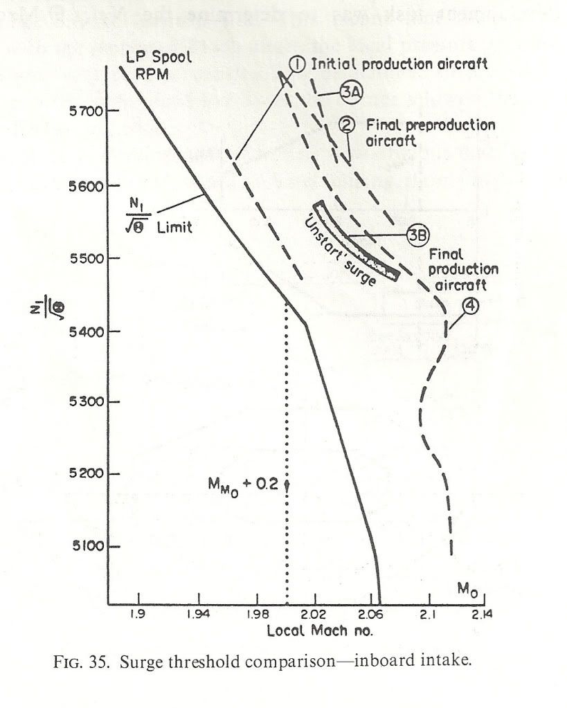 ">The next shows the surge free boundaries in sideslip and normal acceleration. You can see the zero 'g' capability Dude was enthusing over.
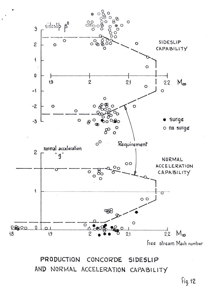 ">
">
As for 'high speed stall', I don't think we ever contemplated trying it! Our requirements in 'g' capability were defined and that was it. Besides, the aircraft would fly like the proverbial stone-built outbuilding at those sorts of conditions so I don't think one would have been able to get anywhere near a stall in the conventional sense. Stall as commonly defined for subsonics (deterrent buffet) might have been another matter, but I don't remember anything.
Cheers
Last edited by CliveL; 13th Jan 2011 at 11:17 . Reason: additional explanation
8th Apr 2011, 18:33
permalink Post: 1285
Fatigue
I saw some questions earlier about performance but that's pretty well documented. I was wondering more about for how much longer ( if there had been no retirement )??
Was there a Fatigue Index as other aircraft of the same era \x96 I only know of the Tornado in this respect: a long calculation was made per flight taken of flight duration, G readings, TO weight, Landing weight etc leaving a small number of 0.0000x per flight. Then added to the current FI to give a forecast of life left. If anyone remembers the Tornado 25FI Update Program debacle in the 90's ???
So how was the Concorde's airframe life calculated ?? Flying hours or perhaps pressurisation cycles ? Did a higher altitude effect anything since there would be a higher differential pressure??
On the Engine side, I remember an Olympus Service Bulletin describing the calculation of Fatigue Cycles for the Oly 200:- There was a calculation with several parameters but instruction to disregard below a certain figure, 85% to Max RPM & back was a regarded as a cycle and the LP Turbine Disc was the component with the lowest number of cycles before the need for overhaul.Was this still the case with the 593 ??
8th Apr 2011, 19:07
permalink Post: 1286
Quote:
| So how was the Concorde's airframe life calculated ?? Flying hours or perhaps pressurisation cycles ? Did a higher altitude effect anything since there would be a higher differential pressure?? |
Not so bad as it sounds in calendar years, as the annual utilisation of any one aircraft was very low, and there would also have been scope for life extension by applying certain modifications to the fuselage.
28th Jul 2011, 08:15
permalink Post: 1410
Dem Kullerz
Glad the Filton AF guys enjoyed their Concorde fix. (There is no other Concorde in the UK, bar none, that able to achieve this fix better than G-BOAC can
 ). As far as the gear door colours go, well the 'normal' colour is the light brown one that you describe, the green primer colour door is a replacement one. (As to when we did that replacement I really can't remember I'm afraid - Extreme Brain Fatigue
).
). As far as the gear door colours go, well the 'normal' colour is the light brown one that you describe, the green primer colour door is a replacement one. (As to when we did that replacement I really can't remember I'm afraid - Extreme Brain Fatigue
).
I'll have a closer look at that door when I'm next up in Manchester in 10 days.
Best Regards
Dude
2nd Sep 2012, 10:56
permalink Post: 1675
@stilton
I can't give you much detail I'm afraid - as JT said a few posts ago:
Basically the differences lie in the fine details of the structure. To quote from a Googled article:
whereas:
On the UK parts there were detailed features such as crack-stoppers and multiple load paths whereas the French design relied on analysis and testing to establish where and when any failures might be expected to occur. The consequence was that the ultimate life of the airframe was dictated by the number of thermal fatigue cycles accumulated in the Farnborough major fatigue facility divided by the factor of safety demanded by the airworthiness authorities which was conservative because one was really into unknown territory.
I can't give you much detail I'm afraid - as JT said a few posts ago:
Quote:
| No point asking Clive .. he's an aerodynamicist and, hence, only talks in slugs/cubic foot. |
Quote:
| Safe-life refers to the philosophy that the component or system is designed to not fail within a certain, defined period. It is assumed that testing and analysis can provide an adequate estimate for the expected lifetime of the component or system. At the end of this expected life, the part is removed from service. |
Quote:
| Fail-safe designs are designs that incorporate various techniques to mitigate losses due to system or component failures. The design assumption is that failure will eventually occur but when it does the device, system or process will fail in a safe manner. |
15th Oct 2015, 09:27
permalink Post: 1905
Bit of a hypothetical question requiring a judgemental response!
My short answer would be not much more than the certified limits - at least not without significant modifications.
FL680 was achieved at the end of a zoom climb, so the Mach No was a lot less than 2.0
M2.23 was in a shallow dive. The object was to demonstrate sufficient margin to avoid surge following the worst temperature transient specified in the TSS regulations. To that end both the intake laws and engine operating lines were tweaked as functions of Mach No to minimise intake flow distortions and maximise surge margin. The result was a long way from the performance optimum one would need for steady cruise.
The power plant was being pushed to its limits at this Mach No.
(As an aside, the subsonic rules make no mention of temperature transients as a cause of Mach exceedences. Some recent incidents suggest this could usefully be reviewed)
The altitude limit could perhaps be more readily expamded. The aircraft normally flew a cruise climb bcause at Concorde cruising altitudes there was no ATC conflict. The altitude was very sensitive to ambient temperature and aircraft weight. FL600 would be associated with end of cruise on a coolish day.
To usefully increase cruise altitude would require more engine thrust, but this could only be obtained by increasing engine TET which would screw the engine fatigue life.
Increasing Mmo from 2.04 would need an increase in Tmo (400 deg K) at any temperature above (from memory) ISA. This in turn would affect the airframe fatigue life unless the structural material were changed. Even then, there were a lot of nonmetallic bits (seals etc) that would also have needed replacement.
Sorry if this is a gloomy assessment, but that is the way I see it!