13th Aug 2010, 18:53
permalink Post: 4
Point taken GF, but it was discovered during development flying that that the Olympus 593 could be relit, given sufficient IAS, at almost any altitude within the normal flight envelope. The variable inlet would even be automatically scheduled, as a funcion of N1, in order to improve relight performance at lower Mach numbers. I certainly agree that you would decelerate and lose altitude fairly quickly under these conditions, however a multiple flame out was never experienced during the entire 34 years of Concorde flight testing and airline operation. There was, as a matter of interest an un-commanded deployment of a Concorde RAT AT MACH 2!! (The first indications of the event were when the cabin crew complained about 'a loud propeller sound under the rear cabin floor'. A quick scan of the F/E's panel revealed the truth of the matter). The aircraft landed at JFK without incident, and the RAT itself, apart from a very small leak on one of the hydraulic pumps, was more or less un-phased by the event. Although it sounds horrific, a prop rotating in a Mach 2 airstream, the IAS it 'felt' would be no more than 530 KTS at any time. The RAT was of course replaced before the aircraft flew back to LHR.
Not quite sure about your reference to the RAT on an F16 being Hydrazine powered; a Ram Air Turbine is just that, using the freely rotatting propellor to power hydraulics, electrics or both. Or do you mean the the F16 has an emergency power unit? Either way, it's fascinating stuff.
Yes, I do remember that the Germans used Hydrazine as a fuel during WW2: The father of one of our Concorde pilots was on an air raid to destroy one o the production plants there, this aviation business is such a small world.
20th Aug 2010, 12:06
permalink Post: 34
Biggles78
I know these fuel flows seem crazy (If take-off fuel flows had been maintained the endurance of the aircraft would have been about 55 minutes!!). But as the majority of the flight was carried out at Mach 2 and above, with the relatively miniscule fuel flows, you can see how we were able to cross the Atlantic with relative ease. It was the subsonic bit that was the pain.
The powerplant was as you say truly amazing. We had an, as yet, unmatched engine/intake combination, with a variable primary and secondary nozzles. The variable intake allowed supersonic operation with maximum pressure recovery, minimum aerodynamic drag, as well as extreme operational stability. (Extreme temperature shears, that would have caused surge/unstarts in military installations) were dealt with as a total non event). It's astonishing to believe, but at Mach 2 cruise, the intake provided approximately 63% of the powerplant thrust. It was controlled by the world's first airborne digital control system. (The system computers were built by the Guided Weapons Division of what was then BAC). The combination of the variable intake, plus the LP and HP compressors gave an overall compression ratio of 80:1.
The engine itself, being supplied with air at an ideal pressure, could run at an almost conststant TET, thanks to the variable primary nozzle. This also allowed N1 and N2 (corrected for total temperature) to be controlled more or less independently and run as close as possible to their separate surge lines throughout the entire flight envelope.
The variable secondary nozzle (wide open above Mach 1.1) allowed the jet efflux to gently expand against a cushion of air that was passed over the rear ramp of the intake, through the engine bay and into the annulus of the nozzle itself. This prevented thrust being wasted by the jet efflux widely splaying as it met ambient air that was at a pressure of as little as 1.04 PSIA.
It was this integrated powerplant that made true supersonic cruise possible
The airframe life issue was sort of like 'how long is a piece of string?'. The airframes are lifed in supersonic cycles, (which had been extended before, with modifications) and studies were always underway as far as further life extensions were concerned. (Basically the airframe was as tough as a brick outhouse in structural terms). The only real area of concern was the crown area (the roof
 ). There was a design flaw here in that the structure had not been designed fail-safe (allegedly by designed a Korean designer at A\xe9rospatiale who, it was said, went a bit loopy). When the FAA evaluated the design (in order for the aircraft to be registered in the USA, for Braniff operations out of IAD) they wanted 'crown planking' to be fitted externally, which would have added over a tonne to the weight of the aircraft, as well as producing some not inconsiderable drag. Fortunately a compromise was reached and additional NDT inspections were carried out, as well as more limited structural modifications. There was a long term, cost effective solution being studied, which would have cured the problem altogether. (The changes would have been mandated, over new requirements for ageing aircraft)
Nick Thomas
Nick, the whole expansion issue was one of the biggest issues that had to be addressed. Wiring looms would 'snake' in some underfllor areas to take up expansion, but the biggest difficulty of all were the mulitudes of hydraulic lines. These required sliding expansion joints, with of course seals to prevent leakage. When a seal deteriorated YPU GOT A LEAK!! (Fluid at 4000 PSI tends torun for freedom very quickly ). As far as fittings go, ChristiaanJ is quite right, you tried to anchor at one end only. I seem to remember that the passenger seat rails travelled over a roller afair. Fuel lines wer less of a problem, because their relative lengths were less.
I also agree wholeheartedly with ChristiaansJ's explanation about the 'friction' thing, I never really liked those stories. As a matter of interest, 127 deg's, for Mach 2, that would be at ISA +5 (-51.5 deg's C). Any warmer than that and we could not achieve Mach 2, due to the Tmo limit of 127. I remember one year, for several weeks we had unusually high north Atlantic temperatures; these impacted both the flight time AND the fuel burn. The further away you were from Mach 2, the higher the fuel consumption. (The faster you flew, the less fuel you burnt. How's that for a paradox?).
At ISA (-56.5 deg's C) temperatures, the total temperature was at around 118 deg's C.
ChristiaanJ
I remember the 17.5 degree position on the nose; it always looked as if the aircraft was trying to eat ants to me . I can not recall personally anyone removing the 12.5 deg' stops for access, although this could of course have been done on your side of the 'puddle' I guess.
As far as the APU ducting issue goes (hee, hee, not often we disagree Christiaan ) we are just going to have to agree to disagee about this, although I accept that two 4" diameter pipes (PLUS THERMAL INSULATION) might have done it, BUT I still stand by the other points.
Stlton
Unfortunately not; the keel beam area was extremely thin and there was not anywhere near enough room. Interesting solution on the 727 though, I never knew that one.
Quote:
Mate, if you could have seen my jaw drop when I read the T/O burn you would probably hurt yourself laughing to much. That is just incredible but the cruise flow seems like stuff all especially considering the speed. The idle flow was also a bit of a jaw dropper.

|
Quote:
| Was surprised, yet again, that Mach 2 was achieved without reheat. They really were/are an amazing powerplant. |
The engine itself, being supplied with air at an ideal pressure, could run at an almost conststant TET, thanks to the variable primary nozzle. This also allowed N1 and N2 (corrected for total temperature) to be controlled more or less independently and run as close as possible to their separate surge lines throughout the entire flight envelope.
The variable secondary nozzle (wide open above Mach 1.1) allowed the jet efflux to gently expand against a cushion of air that was passed over the rear ramp of the intake, through the engine bay and into the annulus of the nozzle itself. This prevented thrust being wasted by the jet efflux widely splaying as it met ambient air that was at a pressure of as little as 1.04 PSIA.
It was this integrated powerplant that made true supersonic cruise possible
Quote:
| On my list of regrets, not getting a flight on Concorde would be in the top 5. If they hadn't grounded them what sort of life did the airframes have left in them? |
). There was a design flaw here in that the structure had not been designed fail-safe (allegedly by designed a Korean designer at A\xe9rospatiale who, it was said, went a bit loopy). When the FAA evaluated the design (in order for the aircraft to be registered in the USA, for Braniff operations out of IAD) they wanted 'crown planking' to be fitted externally, which would have added over a tonne to the weight of the aircraft, as well as producing some not inconsiderable drag. Fortunately a compromise was reached and additional NDT inspections were carried out, as well as more limited structural modifications. There was a long term, cost effective solution being studied, which would have cured the problem altogether. (The changes would have been mandated, over new requirements for ageing aircraft)
Nick Thomas
Nick, the whole expansion issue was one of the biggest issues that had to be addressed. Wiring looms would 'snake' in some underfllor areas to take up expansion, but the biggest difficulty of all were the mulitudes of hydraulic lines. These required sliding expansion joints, with of course seals to prevent leakage. When a seal deteriorated YPU GOT A LEAK!! (Fluid at 4000 PSI tends torun for freedom very quickly
). As far as fittings go, ChristiaanJ is quite right, you tried to anchor at one end only. I seem to remember that the passenger seat rails travelled over a roller afair. Fuel lines wer less of a problem, because their relative lengths were less.
I also agree wholeheartedly with ChristiaansJ's explanation about the 'friction' thing, I never really liked those stories. As a matter of interest, 127 deg's, for Mach 2, that would be at ISA +5 (-51.5 deg's C). Any warmer than that and we could not achieve Mach 2, due to the Tmo limit of 127. I remember one year, for several weeks we had unusually high north Atlantic temperatures; these impacted both the flight time AND the fuel burn. The further away you were from Mach 2, the higher the fuel consumption. (The faster you flew, the less fuel you burnt. How's that for a paradox?).
At ISA (-56.5 deg's C) temperatures, the total temperature was at around 118 deg's C.
ChristiaanJ
I remember the 17.5 degree position on the nose; it always looked as if the aircraft was trying to eat ants to me
. I can not recall personally anyone removing the 12.5 deg' stops for access, although this could of course have been done on your side of the 'puddle' I guess.
As far as the APU ducting issue goes (hee, hee, not often we disagree Christiaan
) we are just going to have to agree to disagee about this, although I accept that two 4" diameter pipes (PLUS THERMAL INSULATION) might have done it, BUT I still stand by the other points.
Stlton
Quote:
|
Not to beat a dead horse, but, on the choice of location for APU, the 727 had a problem with this but for different reasons. Because of the location of the engines that were all mounted at the rear, the Aircraft was quite tail heavy and adding more weight with an APU in the tail section was not desirable.The solution found that I have not seen in any other Aircraft was to mount it in the wheel well transversely across the keel beam with the exhaust out and over the right wing. Quite unusual but it worked fine with the restriction that it could only be operated on the ground.
Its all academic now but, just out of curiosity could this have worked on the Concorde |
24th Aug 2010, 09:48
permalink Post: 88
Biggles78
The tailwheel design really was the one exception in poor design terms, but I'm sure that if the aircraft was doing what she should be doing right now, (you know routinely flying across the Atlantic and beyond, instead of languishing in museums), modifications would have finally put this particular malady to bed). In design terms, the rest of the aircraft was nothing short of a flying work of art, a masterpiece. Having said that though, personally I would rather that four rather than three hydraulic systems had been used. Originally there were four systems in the design, but the RED system was deleted, as it was felt to be superfluous. My own view is that this particular decision was total poppycock. Oh, and Green, Blue and Yellow hydraulic systems was something else that Airbus copied from Concorde.... although we ourselves pinched that idea off of the Comet
).
As far as the hydraulic expansion joints go, I will scour around and see if I can find a diagram for you. Try and picture two titanium (or stainless) tubes, on inside the other, with a sealed chamber being formed at the join. Inside this chamber were multiple lands fitted with special viton GLT seals. They did work incredibly well, although occasionally one of the seals gave out, and things got wet, VERY WET.
As far as the 4000 PSI hydraulic system, as EXWOK quite rightly pointed out, the loading on the flying control surfaces were immense throughout the whole flight envelope. (Picture alone just the T/O from JFK RWY 31L, where the aircraft is tightly turning and the gear retracting, all at the same time). As well as the flying controls and landing gear, you also had the droop nose to consider, four variable engine intakes as well as a couple of hydraulically operated fuel pumps. Oh, and in emergencies, a hydraulically driven 40 KVA generator too. The reason that 4000 PSI was chosen was that if a large amount of hydraulic 'work' was to be done, the only way to keep the size of jacks and actuators to a reasonable size/weight was to increase the system pressure by 25% from the normal 3000 PSI. (On the A380 they've gone a step further and gone for 5000 PSI, saving them over a tonne on the weight of the aircraft).
Concorde used a special hydraulic fluid, Chevron M2V. This is a mineral based fluid, as opposed to the ester based Skydrol, used by the subsonics. The reason that we went for a different fluid was a simple one; Skydrol is rubbish at the high temperatures that Concorde operated at, no good at all in fact, so we needed something better and in M2V we found the PERFECT fluid. As an aside, unlike Skydrol, that attacks paintwork, certain rubber seals, skin, EYES etc., M2V is completely harmless, wash your hair in it. (I did, several times when we had leaks. Thinking about it, maybe THAT is why my hair is such a diminished asset
EXWOK
It's so great having another of my pilot friends diving in to this post, welcome welcome
I remember the Mech' Signalling part of the air tests, my lunch has just finished coming back up thank you. (for interest chaps and chapesses, with mechanical signalling, using just the conventional control runs under the floor, there was no auto-stabilisation).
The artificialfeel system worked incredibly well I thought, I always found it curious that the peak load law in the computer was at the transonic rather that the supersonic speed range. It was explained to me long ago that this was because the controls really are at their most sensitive here, but at high Mach numbers are partially 'stalled out', due to shockwave movements along the surfaces, and were therefore less effective. (For this reason I was told, the inner elevons were so critical for supersonic control, being the most effective of all elevons at high speed).
To all , I forgot to mention in my previous post regarding the engine failure in G-BOAF in 1980; I remember an FAA surveyor, who was taking a look at the carnage within the engine bay, saying that in his opinion, no other aircraft in the world could have survived the intensity of the titanium fire that ensued. Analysis showed that the fire was successfully extinguished, possibly at the first shot of the fire bottle. This was a testament to the way that the Concorde engine bay could be completely 'locked down' when the fire handle was pulled, as well as to the way that the whole engine installation was technically encased in armour plate. To put all this in context, acording to Rolls Royce a titanium fire, once it takes hold, can destroy the compressor of a jet engine in four seconds.
Dude
Quote:
|
M2
, it appears the tailwheel was, so far, the only "fault" in an otherwise extreme machine. Were there any other items like the tailwheel that were unworthy to be in her?
Does anyone have a tech drawing of the "sliding seals" used in the hydraulics. I have trouble visualising something that could withstand the 4,000psi pressure. Why was such a high pressure used? After all the control surfaces couldn't have required that much input to effect an authority movement. I understand it was also a special fluid that was used. Was this because of the pressure it was under or the temperature extremes? |
).
As far as the hydraulic expansion joints go, I will scour around and see if I can find a diagram for you. Try and picture two titanium (or stainless) tubes, on inside the other, with a sealed chamber being formed at the join. Inside this chamber were multiple lands fitted with special viton GLT seals. They did work incredibly well, although occasionally one of the seals gave out, and things got wet, VERY WET.
As far as the 4000 PSI hydraulic system, as EXWOK quite rightly pointed out, the loading on the flying control surfaces were immense throughout the whole flight envelope. (Picture alone just the T/O from JFK RWY 31L, where the aircraft is tightly turning and the gear retracting, all at the same time). As well as the flying controls and landing gear, you also had the droop nose to consider, four variable engine intakes as well as a couple of hydraulically operated fuel pumps. Oh, and in emergencies, a hydraulically driven 40 KVA generator too. The reason that 4000 PSI was chosen was that if a large amount of hydraulic 'work' was to be done, the only way to keep the size of jacks and actuators to a reasonable size/weight was to increase the system pressure by 25% from the normal 3000 PSI. (On the A380 they've gone a step further and gone for 5000 PSI, saving them over a tonne on the weight of the aircraft).
Concorde used a special hydraulic fluid, Chevron M2V. This is a mineral based fluid, as opposed to the ester based Skydrol, used by the subsonics. The reason that we went for a different fluid was a simple one; Skydrol is rubbish at the high temperatures that Concorde operated at, no good at all in fact, so we needed something better and in M2V we found the PERFECT fluid. As an aside, unlike Skydrol, that attacks paintwork, certain rubber seals, skin, EYES etc., M2V is completely harmless, wash your hair in it. (I did, several times when we had leaks. Thinking about it, maybe THAT is why my hair is such a diminished asset
EXWOK
It's so great having another of my pilot friends diving in to this post, welcome welcome
I remember the Mech' Signalling part of the air tests, my lunch has just finished coming back up thank you.
(for interest chaps and chapesses, with mechanical signalling, using just the conventional control runs under the floor, there was no auto-stabilisation).
The artificialfeel system worked incredibly well I thought, I always found it curious that the peak load law in the computer was at the transonic rather that the supersonic speed range. It was explained to me long ago that this was because the controls really are at their most sensitive here, but at high Mach numbers are partially 'stalled out', due to shockwave movements along the surfaces, and were therefore less effective. (For this reason I was told, the inner elevons were so critical for supersonic control, being the most effective of all elevons at high speed).
To all , I forgot to mention in my previous post regarding the engine failure in G-BOAF in 1980; I remember an FAA surveyor, who was taking a look at the carnage within the engine bay, saying that in his opinion, no other aircraft in the world could have survived the intensity of the titanium fire that ensued. Analysis showed that the fire was successfully extinguished, possibly at the first shot of the fire bottle. This was a testament to the way that the Concorde engine bay could be completely 'locked down' when the fire handle was pulled, as well as to the way that the whole engine installation was technically encased in armour plate. To put all this in context, acording to Rolls Royce a titanium fire, once it takes hold, can destroy the compressor of a jet engine in four seconds.
Dude
24th Aug 2010, 22:49
permalink Post: 101
ChristiaanJ
aaah yes, Max Climb/Max Cruise modes. I'd not forgotten this my friend, I was going to say a few words about that in a future post, but maybe we can do that now. (And I'd love to hear more of your comments on this here too, ChristiaanJ). The intake and autopilot modifications were in a way complimentary it's true, but really dealt with separate problems, at least in my view:
The intake control unit software change (a change to the control law that limited engine N1 as a function of intake local Mach number, Mo, and inlet total temperature, T1) was able to put an absolute limit on aircraft achievable Mach number during Mmo overshoots, but it would not PREVENT Mmo overshoots occurring altogether, it was more of a safety brake. This particular overspeed problem manifested itself well before route proving, and in fact the intake system 'fix' resulted in the Thrust Auto Reduce System being deleted, electronic control boxes and all. The TAR system was fitted on all development aircraft equiped with the digital intake system, and it tried (in vain) to limit extreme Mach overshoots. The production aircraft retained the TAR wiring and locked out circuit breakers, as well as two vacant spaces on the electronic racks. The prime reason for all these efforts were that some of the rapid excessive Mach overshoots quite often drove the intake into surge; the modification to this N1 limiter control enabled engine mass flow to be controlled in such a way that these surges could be prevented during temperature shears. The aircraft Mach limit was an extremely useful fringe benefit.
The AFCS mode change from what was Max Op and Max Op Soft (always loved that name) to Max Climb/Max Cruise was at a stroke able to deal with the regular Mmo overspeeds that kept on occuring during, as you say, the route proving trials of 1975, when British aircraft G-BOAC and the French aircrfraft F-BTSD carried out pre entry into service evaluation flights, SD sadly was the aircraft that was tragically lost at Gonez in July 2000). The Max Climb/Max Cruise AFCS mode combo is a mode like no other that I've personally seen before or since anywhere, (it for instance resulted an elsewhere taboo; an autopilot and an autothrotte working together IN A SPEED MODE).
This problem encountered primarily at lower lattitudes, (for example, G-BOAC doing route proving flights out of Singapore), occurring initially as the aircraft reached Mach 2. It was termed 'the insurmountable problem', but the AFCS designers (such as ChristiaanJ) fortunately did not have 'insurmountable problems' in their vocabulary. The issue was that the aircraft would have been climbing rapidly at Vmo of 530 KTS, with throttles at the gate as usual, At exactly 50,189' we hit what was known as 'the corner point' in the flight envelope, where 530 KTS IAS equated to Mach 2 exactly. Max Op mode would then 'let go' of the Vmo segment, and try and control the aircraft to Mach 2. (As the aircraft climbed, Vmo itself would progreesively decrease in order to equate to Mmo, or 2.04 Mach). But in very cold conditions, the aircraft still 'wanting' to accelerate, and the simple Max Op/Max Op Soft modes just could not cope with gentle pitch changes alone. The problem became even bigger during the cruise/climb when severe temperature shears occured, and routinely regular Mmo exceedences occured. Something had to be done, and something WAS done and how; enter Max Climb/Max Cruise. It was really a classic piece of design, where the aircraft would do the initial supersonic climb in Max Climb mode. This mode itself was relatively simple, in that it was more or less a Vmo -Vc hold mode. That meant that the difference at selection between indicated airspeed, Vc and Vmo would be maintained, with a vernier datum adjust to this being available. In practice this mode was selected pretty much at Vmo, so datum adjusting was not always required. Now comes the clever part; the autothrottle, this would operate in standy mode at this point, just waiting there doing nothing, with the throttles at maximum as before. So the aircraft would now climb as Vmo increased to 530 KTS, and then following a now constant Vmo of 530 KTS until the magic 'corner point' (51, 189' remember). Now all hell would break loose; the mode would automatically change to Max Cruise, the autothrottle would also be automaically selected to Mach Hold mode (initially datumed here to Mach 2) and the throttles would retard, attempting to hold this Mach 2 datum, and the autopilot is commands a 'fly up' signal, over a 20 second lag period to 600'/minute. Now comes an even cleverer (?) part; the autothrottle Mach Hold datum is gradually increased over a 100 second period towards Mach 2.02, and so in stable conditions the throttles would now gradually increase again until they once more reach the maximum limit. At this point, the autothrottles now come out of Mach Hold mode and back into the waiting in the wings standby mode. The autopilot would now cancel it's 600' fly up, demand, returning to a datum of Mach 2. There was a little more complexity built in also, where the difference between the 'commanded' and actual vertical speeds offset the autoplilot Mach 2 datum. This would apply whether the autothrottle had cut in (+600'/min demand) or with the throttles back at maximum (0'/minute demand. A positive climb error tweaked the cruise Mach up slightly, a negative error (eg. in a turn) the converse was true. The effect of all of this complexity was that the aircraft itself could 'scan' until it settled at a point where the throttles could be at maximum, and the speed between Mach 2 and 2.02. On the North Atlantic, with warmer ISA temperatures, there was usually just the initial routine with the autothrottle as you hit the corner point. However at lower lattitudes (eg. LHR BGI) there could be a few initial autothrottle intercepts before things settled down. This whole incredible routine completely took care of the insurmountable problem, a problem that was shown not only to be insurmountable, but was put to bed forever, by people like ChristiaanJ.
I hope that my explanation here does not sound too much like gibberish.
EXWOK
I think you've guessed right as far as my identity goes; it's great that it's not just Concorde pilots I can bore the socks off now
PS. I bet the ex-SEOs LOVED your comments
Dude
Last edited by M2dude; 25th Aug 2010 at 01:14 . Reason: missed out some info' (sorry)
5th Sep 2010, 02:29
permalink Post: 215
It was certificated - up to a point. Problematic? Maybe not, but it was a part of the flt envelope to be treated with respect.
Obviously there are no spoilers, and once you translate to 'vortex lift' (stalled in conventional terms) there is definitely no shortage of drag. (This happened at about 250kts at landing weight).
Supersonic - it was certainly no sailplane and an ability to increase drag wasn't required.
So - there is a bit of the flight envelope where you are subsonic, descending at about 350kts IAS, where you may need a bit of drag; e.g. to make the FL140 limit on the OCK 1A SID (as it then was) to LHR.
To facilitate this, engines 2 and 3 could be selected to reverse idle within certain strict limitations (most of which have now left my brain). The mechanism was to ask the SFE to arm the system on his panel and then to select reverse on the inboards. Where the system was slightly unreliable was that you were running the air-driven buckets with the engines at idle thrust - consequently they sometimes didn't make a full reverse selection, in which case you canx reverse on that engine and managed on one.
Clearly the big event would be if they didn't translate into fwd thrust, which is one of the reasons it wasn't done below 10 000'. I'm not aware of this happening.
To be honest it was only really used when ATC threw an alt constraint at you during the descent, because in general if you just pitched down to 380kts (Vmo when subsonic at typical approach weights) you would get the height off comfortably.
5th Sep 2010, 21:02
permalink Post: 220
Nick
,
Again I'll leave the full details to the real experts....
I saw that program with James May in the U2 too, so I know what you mean.
The "coffin corner" is the point for a subsonic aircraft where stall speed and limiting Mach number "meet" ; about 70000 ft for a U2, and considerably lower for an airliner. Either you stall, or you run into Mach buffet with control problems.
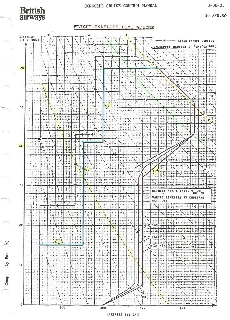
I'll try and find you a proper picture of the Concorde flight envelope (I have a few but one isn't scannable, the other is too ancient - preprod, yet another is 'buried' on a CD).
But nearly all of the edges and corners in that flight envelope "window" are a matter of certification.
You're not supposed to exceed M=2.04, Tt=127\xb0C, IAS= 530kts, simply because of the "wear and tear" on the aircraft.
You're not supposed to go above 60000ft because your passengers might no longer survive a window blow-out.
You're not supposed to go below 300kts above 41000ft, don't know if that's a minimum control speed or linked to the engines...
Yet Concorde has been flown to Mach=2.23 and 68000ft without ill efect....
So the basic limitations are not linked to the classic "coffin corner" at all.
CJ
Again I'll leave the full details to the real experts....
I saw that program with James May in the U2 too, so I know what you mean.
The "coffin corner" is the point for a subsonic aircraft where stall speed and limiting Mach number "meet" ; about 70000 ft for a U2, and considerably lower for an airliner. Either you stall, or you run into Mach buffet with control problems.
I'll try and find you a proper picture of the Concorde flight envelope (I have a few but one isn't scannable, the other is too ancient - preprod, yet another is 'buried' on a CD).
But nearly all of the edges and corners in that flight envelope "window" are a matter of certification.
You're not supposed to exceed M=2.04, Tt=127\xb0C, IAS= 530kts, simply because of the "wear and tear" on the aircraft.
You're not supposed to go above 60000ft because your passengers might no longer survive a window blow-out.
You're not supposed to go below 300kts above 41000ft, don't know if that's a minimum control speed or linked to the engines...
Yet Concorde has been flown to Mach=2.23 and 68000ft without ill efect....
So the basic limitations are not linked to the classic "coffin corner" at all.
CJ
6th Sep 2010, 09:17
permalink Post: 222
Coffin Corner
Nick Thomas
Just like Christiaanj I'm trying to dig up an accurate flight envelope diagram. (A lot of my Concorde 'technical library' is out on long term loan), but I would suggest that anywhere within Concorde's published flight envelope you never hit any equivilant to Coffin Corner, a la' U2. The whole issue is really one of air DENSITY, rather that pressure, where as you climb at a given Mach Number, your Indicated airspeed (IAS) falls away with altitude. (Velocity of sound being primarily tied to static air temperature). Now if you are climbing in the stratosphere, where temperature is more or less constant up to around 65,000', you can say that your TRUE Airspeed (TAS) is also constant with climb at a given Mach number. But lift and drag are functions of IAS (the equivalent airspeed that the aircraft would 'feel' at sea level) and not TAS. Because the U2 had a very low Maximum allowable Mach number (Mmo) as IAS fell away with altitude, it would get to the point where it's lowest permitted airspeed (we called this VLA) got to within a few knots of Mmo and severe aerodynamic buffering. i.e. you were screwed with nowhere to go but down
.
In the case of Concorde, Mach 2 at FL500 was 530KTS, falling to 430KTS at FL600. Although we have less lift due to 100KTS lower IAS, the aircraft is now much lighter (this is the whole principal of cruise/climb) which keeps the universe in balance, but drag is now significantly lower too, getting us better MPG
.
On the ASI, the only limitation displayed was Vmo; however the Machmeter did display fwd and aft CG limits at a given Mach number. The ONLY time that Concorde would experience relatively low speeds at altitude was at Top of Descent. I'm a little fuzzy here how it all worked exactly (it's an age thing you know), I'm sure one of the pilots can correct me, but I seem to remember that the autothrottle was disconnected, ALTITUDE HOLD was selected on the AFCS, and the throttles slowly retarded. (If you pulled back too far you'd often get a gentle 'pop surge' from the engines, and you had also to be wary of equipment cooling airflow too). The aircraft was then allowed to gently decelerate, still at TOD altitude, until Mach 1.6, when power was tweaked to give 350KTS IAS and IAS HOLD was selected. The aircraft was now free to carry out her loooong descent to 'normal' altitudes. VLA on Concorde was not directly displayed as you never flew anywhere near it, and also every pilot knew his VLA
. (Stray into this and you'd get a 'stick' shaker warning.
I hope this blurb helps Nick
Dude
6th Sep 2010, 12:52
permalink Post: 225
M2dude
Is this what you're looking for?
Best Regards
Bellerophon
Is this what you're looking for?
Best Regards
Bellerophon
6th Sep 2010, 14:40
permalink Post: 228
Hi all,
Re the flight envelope diagram, Bellerophon got ahead of me, and his scan is cleaner than mine!
I've got a second one, which is basically the same, but has the envelope for a CG of 55% and for a CG of 59% hatched in.
For anybody who wants the full scans to print them out in A4, use these links.
Flight envelope A4 format
light envelope w. CG limits A4 format
Apologies for the mediocre quality of the scans...
CJ
6th Sep 2010, 15:25
permalink Post: 230
Thanks Bellerophon and CJ for posting the flight envelope. With regard to the CofG of 59%, I notice that the upper part of the envelope abuts the MMO boundary.So is the Cof G of 59% the determining factor for the MMO or is it some other factor?
Regards
Nick
Regards
Nick
6th Sep 2010, 17:13
permalink Post: 233
Nick:
The top of the boundary is FL600, largely an artificial number - the airframe is good for rather higher than this, but I believe air supply and ramp scheduling could become an issue not so far above this level.
Mmo - ditto. As others have said, Mmo was originally going to be higher (M2.2) but was reduced to extend fatigue life as the aircraft design 'grew'.
The significance of the shaded 59% portion of the graph is that it shows the envelope at that CG - in this case the relevant line is the bottom of the shaded area - M1.56. This is the MINIMUM mach number that can be flown with the CG at 59% (normal for supersonic cruise). You will see it represented on the Machmeter (a few pages back) as the "AFT" bug. i.e. you can't fly slower than this without moving the CG forward.
So it can be seen that the decel must be done in concert with CG transfer - and as (mostly) always the designers had made it as straightforward as possible. Transferring forward from Tank 11 using the two electric pumps the rate of txfr pretty well matched the standard decel profile, leaving the FE to make the occasional tweak to keep the flight envelope in concert with the CG envelope through the decel/descent.
In the case of abnormal procedures depriving one of electrical power then some other way had to be found to enable a descent (which required a decel) and that is why there are also two hydraulically driven fuel transfer pumps in tank 11.
It's a bit confusing at first, but there are two overlapping flight envelopes - the speeds/alts drawn on the basic envelope and those determined by the CG postion at the time.
In practice - one had a takeoff CG, a landing CG, a subsonic crz CG, a supersonic cruise CG and the only area one had to keep a close eye on was the transition between the last two. There were several visual and aural warnings to back up the CG and Machmeter bugs.
Quote:
| So is the Cof G of 59% the determining factor for the MMO or is it some other factor? |
Mmo - ditto. As others have said, Mmo was originally going to be higher (M2.2) but was reduced to extend fatigue life as the aircraft design 'grew'.
The significance of the shaded 59% portion of the graph is that it shows the envelope at that CG - in this case the relevant line is the bottom of the shaded area - M1.56. This is the MINIMUM mach number that can be flown with the CG at 59% (normal for supersonic cruise). You will see it represented on the Machmeter (a few pages back) as the "AFT" bug. i.e. you can't fly slower than this without moving the CG forward.
So it can be seen that the decel must be done in concert with CG transfer - and as (mostly) always the designers had made it as straightforward as possible. Transferring forward from Tank 11 using the two electric pumps the rate of txfr pretty well matched the standard decel profile, leaving the FE to make the occasional tweak to keep the flight envelope in concert with the CG envelope through the decel/descent.
In the case of abnormal procedures depriving one of electrical power then some other way had to be found to enable a descent (which required a decel) and that is why there are also two hydraulically driven fuel transfer pumps in tank 11.
It's a bit confusing at first, but there are two overlapping flight envelopes - the speeds/alts drawn on the basic envelope and those determined by the CG postion at the time.
In practice - one had a takeoff CG, a landing CG, a subsonic crz CG, a supersonic cruise CG and the only area one had to keep a close eye on was the transition between the last two. There were several visual and aural warnings to back up the CG and Machmeter bugs.
7th Sep 2010, 07:12
permalink Post: 244
 Hi guys, here is a schedule showing CG against Mach number (It's very old just like the author here). I hope that it now completes our collection of flight envelope diagrams.
(
Bellerophon, by the way, your diagram is precisely the one that I was scouring around for). Great explanations by everybody on the Mach/TAS/IAS etc issue, mostly all clear and concise ( a couple of minor goofs that were subsequently corrected, otherwise very good) .
Hi guys, here is a schedule showing CG against Mach number (It's very old just like the author here). I hope that it now completes our collection of flight envelope diagrams.
(
Bellerophon, by the way, your diagram is precisely the one that I was scouring around for). Great explanations by everybody on the Mach/TAS/IAS etc issue, mostly all clear and concise ( a couple of minor goofs that were subsequently corrected, otherwise very good) .
If I were in the LEAST bit pedantic (and any here that know me would say that the b****d certainly IS
 pedantic), I would merely add that Concorde (like virtually all complex aircraft) relied on CALIBRATED airspeed (Vc) and not IAS, taking into acount plate and probe errors. Just as well I'm not pedantic
.
pedantic), I would merely add that Concorde (like virtually all complex aircraft) relied on CALIBRATED airspeed (Vc) and not IAS, taking into acount plate and probe errors. Just as well I'm not pedantic
.
Dude
Last edited by M2dude; 7th Oct 2010 at 18:12 .
30th Sep 2010, 15:03
permalink Post: 500
I copied this off M2dude's post a couple of days ago, and tried to answer it all offline without cheating by looking up the answers elsewhere.
1) How many fuel tanks were there on Concorde?
LOL... 13.
I suppose that, for the same reason there was no row 13 in the cabin, somebody decided to name two of the tanks "5A" and "7A", rather than call the tail trim tank (named no.11) number 13.
Yes, I forgot the scavenge tank.
And since it was "BA Concordes only" I didn't want to add the hydrazine tank on the two preprod and the two certification aircraft.
2) How many seats were there?
Good question.
As Nick asked, which seats?
Nominally there were 100 pax seats in the cabin, although originally up to 127 were certified.
Five (three plus two jump seats) in the cockpit.
Cabin seats for the cabin crew.... I honestly don't know. Seven?
Wrong twice... six cabin crew seats, AND I forgot to count the loos!
3) At what approximate altitude and KNOTS EAS was Mach 2 achieved?
Roughly, FL500 and 530 kts.
But not being a pilot I had to check an instant on my flight envelope crib sheet, which I have at hand all the time.....
It seemed pointless to be TOO precise, because that assumed ISA and creeping exactly up the right edge of the envelope.
4) Only one BA Concorde had three different registrations, what was it?
Without looking it up, no idea. My guess is G-BOAF, with a white-tail reg, a "British" reg, and a pseudo-American reg.
IIRC, G-BOAG never had a pseudo-American reg, but I'm not sure without looking it up.
Brain not completely addled, then.
5) What was the maximum permitted altitude in passenger service?
FL600, as certified.
6) How many wheels on the aircraft?
Twelve, if you count the two Spitfire wheels at the back
7) How many flying control modes were there?
Four. Blue, green, mechanical and ... what did we call it? Control jam, CWS?
Ah, thanks, Emergency Flight Control. I always considered it as a separate mode, even if it was virtually never used.
8) How many positions of nose droop were there?
Four. 0\xb0, 5\xb0, 12.5\xb0 and 17.5\xb0 (the latter only on the prototypes, and purely mechanically, after removing a stop, on the other aircraft).
9) What was the first microprocessor application on the aircraft?
No idea... you (M2dude) mentioned a Plessey data acquisition system?
It was after "my time"...
10) How many main electrical sources were there?
Again, not sure... You're presumably are talking about primary sources.
There was an AC constant-drive generator on each engine.
Then there were two DC batteries.
And IIRC there was an AC generator running off the RAT hydraulic generator when pillar came to post.
Reading M2dude's answer, I suppose the emergency generator just ran off the hydraulics, not specifically off the RAT. Far more logical.
Nice one, M2dude!
And certainly not all trivia!
CJ
8th Oct 2010, 09:06
permalink Post: 528
Feathers McGraw
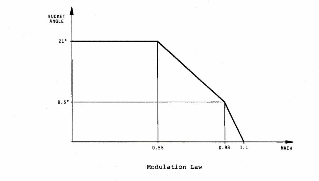
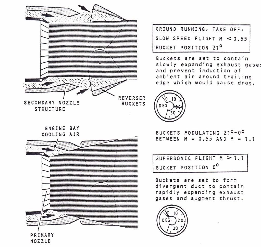
The 10 degree lockout position was a bit of a compromise, to allow the aircraft to operate throughout the normal operating envelope with a secondary nozzle (bucket) at a less than ideal position. See the diagrams below, one showing the bucket control schedule and the other the bucket positions at both take off and supersonic flight: If the buckets are too wide at low Mach numbers then the high velocity exhaust will try and 'drag' the low pressure/low velocity air in the exhaust annulus along with it; this results in a huge reduction in thrust and is termed 'base drag'. That is the whole idea of having the eyelids at the top and bottom of the bucket assembly; to admit free ambient air into this void and mitigate the effects of base drag (and reduce the noise mayhem a little too). If however the buckets are too narrow at high speed/high altitude then we really get a problem; The high pressure/high velocity exhause gas immediately expands against the VERY low presuure ambient air and flares outwards at an accute angle, again losing us serious quantities of thrust The wide open bucket angle gives us this wonderful cushion of secondary intake airflow. (travelling over the top of the rear ramp, through the engine bay and into the nozzle annulus. The eflux can now gently expand against this airflow as it exits the secondary nozzle, taking up the shape of the divergent secion of nozzle.
Now if we are locked at the 10 degree position we are at a position that will give us significant but tolerable losses throughout the flight envelope.
Quote:
| I presume that the fuel penalty for a locked secondary nozzle was due to the reduced expansion of exhaust gas without the maximum divergent shape? |
Now if we are locked at the 10 degree position we are at a position that will give us significant but tolerable losses throughout the flight envelope.
22nd Oct 2010, 09:26
permalink Post: 597
OK guys, here are the answers. If you disagree about any of them then fire away, the old memory certainly 'aint perfect.
As many of you have guessed, there were 22: The 14 production airframes, the 2 production series development aircraft (201 & 202), the 2 pre-production airframes (101 & 102) and the 2 prototypes 001 & 002. PLUS, the major fatigue test specimen at the RAE Farnborough and the static test specimen at CEAT in Toulouse. The CEAT tests actually tested the wing to destruction; I seem to remember it was something like a 200% overload before the wing failed at the root. And great but rather sad pictures
VOLUME
, never seen these before.
OK, from MY memory
 , we have: London LHR (duhhh!!), Bahrein BAH, Singapore SIN, New York JFK, Washington IAD, Dallas DFW, Miami MIA, Toronto YYZ, Barbados BGI, and Riyadh RUH. As well as charters being ommited, so are some of the special 'surprise' shuttle appearances that Concorde would make, substituting a subsonic to and from destinations such as Manchester and Edinburgh.
11:15
The BA193 and BA 195.
OK, there were 12 engine feed pumps (3 per engine) 8 main transfer tank pumps (2 each for the transfer tanks 5, 6, 7 & 8), 4 'A' tank pumps (2 each for 5A & 7A), 8 trim-transfer tank pumps (2 electric pumps each for tanks 9, 10 & 11 PLUS 2 hydraulically driven pumps for tank 9), 4 electric engine start pumps (there was a single electric start pump per engine that delivered fuel to it's own dedicated start atomiser in the combustion chamber. The pump automatically ran when the engine HP valve was set to OPEN and would continue running for 30 seconds after the DEBOW switch was returned to the 'normal' position), 4 engine first stage pumps (a single mechanically driven pump per engine), 4 second stage pumps (a single pneumatically driven pump, sometimes termed 'the turbopump, per engine. This would cut out at around 20,000'), our scavenge tank pump (triggered automatically when there was 7 US gallons in the tank; pumping it back into tank 2. This pump was identical to an 'A' tank transfer pump), and FINALLY, a single de-air pump for tank 10. The pump would drive the fuel through a mesh, removing air bubbles from the fuel. Tank 11 used the L/H trim pump for de-air (similar principle)and would be switched on during take-off. This is why the tank 5 trim inlet valve being set to over-ride OPEN would result in the tank being highly pressurised in the case of the Gonesse disaster; the pump would obviously pressurise the L/H trim gallery and any tank on that side with an open inlet valve!!!
G-AXDN, aircraft 101. (A production wing, fuselage, droop nose and intakes, but with the short tail section and secondary nozzles of the prototypes.
Ready ChristiaanJ? There were 18....Yes, the single SFENA standby horizon, 9 INS gyros (one per X,Y and Z platform in each of the 3 INUs), 8 autostab' rate gyros (one per axis for each of the 2 autostab' computers PLUS a monitor gyro for the pitch axis). The radar by the way used attitude signals from the INS.
9. One per main wheel plus the single 'in flight braking' nose wheel brake.
Mach 0.7!!! Between this and Mach 1.26 the intake surfaces were positioned as a function of engine N1 if the engine was shut down for any reason. (Otherwise of course the intake surfaces were fully up). You needed a sub idle N1 of 57% and below for all this to happen, and it was to assist relight performance and reduce buffet. Between Mach 1.26 and 1.32 the ramps were driven down slightly to about 5%, full supersonic scheduling itself commencing at Mach 1.32.
Already brilliantly answered by Brit312 (as well as the FSLabs diagram). Yep, Geen GO, T/O monitor armed, fuel flow and P7 at or above datum, A/C on ground, reverse not selected and CON light not on. Amber CON (Reheat selected and not detected, N1 OK or reverse selected and primary nozzle (Aj) not at minimum. Blue REV; steady buckets at reverse, flashing buckets in transit.
Fairford, followed by Brize Norton, and then a host of airfields from Prestwick and Shannon to Chateauroux.
OK, probably no surprises now:
Landing - 27L & R, 9L & R (prior to LHR mag' deviation update were 28L & R & 10L & R) together with 23/05.
Take off - 27L (28L), 9R (10R) and 9L. (10L never happened as take offs on this runway only occurred in 2003).
It was FedEx, they planned to operate two stripped out aircraft, leased from BA, between Shannon and JFK as high value parcel carriers. The idea was that parcels would be flown in from all over Europe by small FedEx feeder aircraft and the parcels transferred to Concorde which would then speed on to JFK in around 2 1/2 hours. It never happened because of a combination of economics appraisal by FedEx and BA deciding that it could would not release the aircraft anyway.
A/C 101, G-AXDN first flew on 17th December 1971 with FIXED INTAKES!! (101 was going to be the launch vehicle for the new digital intake control system, but the 'boxes' were still being designed). This placed an operating limit of Mach 1.5 on the aircraft, limiting her ability with such a restricted flight envelope. She returned to Filton in late 1972 for installation of the system, as well as the new Olympus 593-602 engine. (The engine, very similar to the production Mk 610 version, used a quite revolutionary annular combustion chamber, and eliminated at a stroke the thick smoke exhaust that had up to then been Concorde's unwanted visual signiture). The aircraft flew more or less smokeless on 15 March 1973, achieving Mach 2 soon afterwards. As ChristiaanJ pointed out, the British prototype 002 had a similar gap, actually significantly higher, of 19 months. (The French aircraft 001 had an even longer gap of some 20 months).
I hope you guys had fun with this one, regards to all
Dude
Quote:
| 1) How many Concorde airframes were built? |
Quote:
| 2) As far as the British constructed aircraft went, name the destinations that were served?. Regular flight numbers only, excludes charters etc. |
, we have: London LHR (duhhh!!), Bahrein BAH, Singapore SIN, New York JFK, Washington IAD, Dallas DFW, Miami MIA, Toronto YYZ, Barbados BGI, and Riyadh RUH. As well as charters being ommited, so are some of the special 'surprise' shuttle appearances that Concorde would make, substituting a subsonic to and from destinations such as Manchester and Edinburgh.
Quote:
| 3) What was the departure time for the ORIGINAL morning LHR-JFK Concorde services? (Not called the BA001 then either). |
Quote:
| 4) Further to question 3 above, what WERE the original flight numbers for the BA001 and BA003? (The morning and evening LHR-JFK services?). |
Quote:
5) There were no less than FORTY SIX fuel pumps on Concorde. What was the breakdown for these? (Clue; don't forget the scavenge pump
 ).
).
|
Quote:
| 6) What was the only development airframe to have a TOTALLY unique shape? |
Quote:
| 7) This one is particularly aimed at ChristiaanJ. What was the total number of gyros on the aircraft? |
Quote:
| 8) How many wheel brakes? |
Quote:
| 9) What Mach number was automatic engine variable intake control enabled? |
Quote:
| 10) Above each bank of engine instruments were three lights, a blue, a green and an amber. What did they each signify? |
Quote:
| 11) At what airfield were the first BA crew base training details held? |
Quote:
| 12) What LHR runways did Concorde use for landing and take-off? (Trick question, not as obvious as it might seem). |
Landing - 27L & R, 9L & R (prior to LHR mag' deviation update were 28L & R & 10L & R) together with 23/05.
Take off - 27L (28L), 9R (10R) and 9L. (10L never happened as take offs on this runway only occurred in 2003).
Quote:
| 13) What operator had serious plans to operate Concorde from SNN to JFK in the early 1980's? |
Quote:
| 14) What development aircraft did not exceed Mach 2 until fifteen months after her maiden flight? |
I hope you guys had fun with this one, regards to all
Dude
Last edited by M2dude; 22nd Oct 2010 at 11:21 . Reason: oops, misssed out question 2
22nd Dec 2010, 14:50
permalink Post: 941
Quote:
|
Originally Posted by
M2dude
Concorde had triple-axis auto stabilisation, where pilot demands were routed via an AUTOSTAB COMPUTER and summed with any stabilisation demands.
|
Pilot demands in manual flight produced electrical signals corresponding to the control position, which were sent to the 'servo control amplifiers' (eight in all, one per control surface) which in turn commanded the PFCUs (power flying control units) that hydraulically moved the control surfaces.
Autopilot demands directly moved the pilot's controls (stick and rudder) via hydraulic cylinders (the 'relay jacks') so that the same signals as in manual flight then went to the servo control amplifiers.
The purpose of the autostab was to provide proper dynamic stability over the full flight envelope. The aircraft could be flown without autostab, but over some of the speed range it was only marginally stable.
The electrical signals from the autostab computing were fed directly into the servo control amplifiers, so there was no feedback to the pilot's controls, unlike the autopilot demands.
There was occasional confusion about exactly what did what and how and where.... because the servo control amplifiers - although a function independent of the autostab as such - were housed... in the autostab computers.
To complete the tale, this is what those servo control amplifiers look like.
The one of the left is from prototype 002, the one on the right from a production aircraft. To give them scale, the one on the right is about the size of a box of large kitchen/fireplace matches.
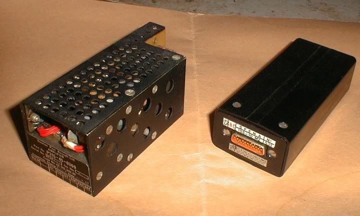
CJ
25th Dec 2010, 22:37
permalink Post: 1007
Quote:
|
Originally Posted by
Mike-Bracknell

We all know Concorde went at Mach 2 at FL600, but were there instances (for the press, certification, etc) that you went supersonic considerably closer to the deck? and what issues (if any) did that bring up?
|
Flight envelope
Those are the official certified limits.
I doubt somehow anybody went beyond those "for the press".....
But during certification, yes, each of those limits was exceeded, slowly and carefully, to be able to draw those official operational limits on the document.
For instance, the certified Mmo is 2.04. During certification, G-BBDG (202) went to Mach 2.21....
Even while staying within the limits, she could could exceed Mach 1 just below 30,000 ft.
Also, during the acceptance flights after major overhauls, most of those envelope limits would be exceeded by a given margin, to prove the aircraft still met all the certification requirements. Whether any of that was done 'closer to the deck', I wouldn't know.
The 'issues' would vary. Performance would be one issue... Delta Golf (and 01, who went to Mach 2.23) basically "ran out of steam" at that speed.
Another issue would be that 'going beyond the borders' shortened the fatigue life of the airframe, and it was difficult to assess exactly by how much. It was one of the reasons why Delta Golf and Sierra Bravo (the certification aircraft) in the end never went into service.
CJ
26th Dec 2010, 15:58
permalink Post: 1016
For convenience, I repeat Bellerophon's diagram of the flight envelope here.
Mike's earlier question had me scratching my head too, hence my question.
What are the fundamental reasons for each of the limitations, and what were the consequences of going outside them?
Going clockwise from the left, we have :
VLA (lowest admissible speed)
One would expect a curve for constant alpha max against IAS and altitude, not the staircase in the diagram.
Was this for simplicity of use of the diagram?
Max altitude (60,000ft)
This is the 'simplest' one: it was the highest 'safe' altitude from which an emergency descent could be made, in the case of a window blowing out, without having the blood of the pax boil....
Test flights (without pax, and with the crew pressure-breathing oxygen) did go as high as 69,000ft.
Mmo (max operating Mach number)
Mach 2.04 is usually quoted as having been chosen to assure an adequate life of the airframe.
But what effect does a higher Mach number as such have?
Or are Mmo and Tmo (127\xb0C) directly related?
Vmo (max operating speed) = 530kts until 43,000ft
I suppose this is related to structural limits (qmax)?
Vmo reducing to 380/400kts at about 33,000ft
What is the limiting factor here (other than qmax)?
Vmo constant at 380/400kts down to 5,000ft
What is the limiting factor here? The answer will no doubt also explain why this is slightly weight-dependent.
Vmo reducing to 300kts between 5,000ft and 0 ft
Why the sudden change below 5,000ft?
CJ
29th Dec 2010, 03:57
permalink Post: 1037
911slf
...I have been a Concorde fan since I won a flight on it in 1980...
Lucky devil! I'm glad you enjoyed the flight.
...There appears to be two digital displays per gauge as well as an analogue display...
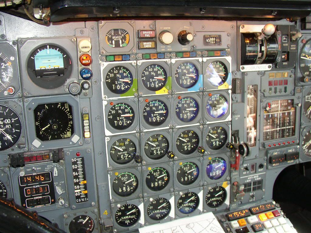
Only the lower digital counter was actually a display, and was a digital repeater of the total fuel flow information being displayed by the pointer on the dial. The upper digital counter was merely a digital indication of the value to which the internal yellow triangular bug had been set by the F/E using the bug setting knob on the lower right of the gauge.
Very briefly, during the pre-flight set up, the F/E would calculated the expected fuel flows for each engine, during the take-off whilst using re-heats. He would set this on the bug, and this achieved two things.
Firstly, it gave him a good visual indication whether the required fuel flows were being achieved. Too low a fuel flow would indicate a re-heat problem on that engine.
Secondly, it programmed the expected fuel flow into the engine take-off monitor, as this was one of the parameters that had to be satisfied in order for the monitor to illuminate the Green \x93Clear-to-Go\x94 light.
The Green \x93Clear-to-Go\x94 light was one of three \x93Power Management\x94 lights immediately above the N2 gauge for each engine, the other two being an Amber \x93Configuration\x94 light and a Blue \x93Reverse\x94 light. Some take-offs would require all four Green lights to be on, other take-offs, depending on ambient conditions, aircraft weight and runway length, might only require three Green lights.
...What was the peak consumption per engine, and why two digital displays on each gauge?...
The maximum peak consumption predicted was 21,700 kg/eng/hr, or 86,800 kg/hr total. This would have been predicted for a re-heated take-off, at +8\xb0C, at an elevation of -1,000 PA.
More typically, on a standard day, at a sea level airfield, 20,700 kg/eng/hr, or 82,800 kg/hr total. You can probably see why we turned the re-heats off fairly quickly!
...accelerating to Mach 2.0 and immediately slowing down again....we only went to 43,000 feet so the sky did not get very dark...
43,000 ft is actually a bit too low for Concorde to be at M2.0, as you may see from this graph of her Flight Envelope. She would have been limited to around 525 kts / M1.7 at that height, so I suspect you may have been a little higher than you remember, possibly somewhere around 53,000 ft.
Happy New Year
Bellerophon
...I have been a Concorde fan since I won a flight on it in 1980...
Lucky devil! I'm glad you enjoyed the flight.
...There appears to be two digital displays per gauge as well as an analogue display...
Only the lower digital counter was actually a display, and was a digital repeater of the total fuel flow information being displayed by the pointer on the dial. The upper digital counter was merely a digital indication of the value to which the internal yellow triangular bug had been set by the F/E using the bug setting knob on the lower right of the gauge.
Very briefly, during the pre-flight set up, the F/E would calculated the expected fuel flows for each engine, during the take-off whilst using re-heats. He would set this on the bug, and this achieved two things.
Firstly, it gave him a good visual indication whether the required fuel flows were being achieved. Too low a fuel flow would indicate a re-heat problem on that engine.
Secondly, it programmed the expected fuel flow into the engine take-off monitor, as this was one of the parameters that had to be satisfied in order for the monitor to illuminate the Green \x93Clear-to-Go\x94 light.
The Green \x93Clear-to-Go\x94 light was one of three \x93Power Management\x94 lights immediately above the N2 gauge for each engine, the other two being an Amber \x93Configuration\x94 light and a Blue \x93Reverse\x94 light. Some take-offs would require all four Green lights to be on, other take-offs, depending on ambient conditions, aircraft weight and runway length, might only require three Green lights.
...What was the peak consumption per engine, and why two digital displays on each gauge?...
The maximum peak consumption predicted was 21,700 kg/eng/hr, or 86,800 kg/hr total. This would have been predicted for a re-heated take-off, at +8\xb0C, at an elevation of -1,000 PA.
More typically, on a standard day, at a sea level airfield, 20,700 kg/eng/hr, or 82,800 kg/hr total. You can probably see why we turned the re-heats off fairly quickly!
...accelerating to Mach 2.0 and immediately slowing down again....we only went to 43,000 feet so the sky did not get very dark...
43,000 ft is actually a bit too low for Concorde to be at M2.0, as you may see from this graph of her Flight Envelope. She would have been limited to around 525 kts / M1.7 at that height, so I suspect you may have been a little higher than you remember, possibly somewhere around 53,000 ft.
Happy New Year
Bellerophon
17th Apr 2011, 10:40
permalink Post: 1300
agreed Dude...
202 was built as 2nd Production, with a defined role as a test aircraft. Several studies were carried out over the years to see if she could be reused. Initially with the manufacturers, where if Concorde has been a success she could have been refurbished and sold to another airline at a "good" price. Of course here flying outside the certified flight envelope led to a lot of further concerns that really was curtains for any modification.
BA had robbed a lot of parts from her in the 80s, especially to bring G-BOAG back into service, so it was a no brainier in the end to put her in a hangar and rob whatever was required to kept the fleet of 7 in the air.
One little point, in the very late 70s here MEPU was decommissioned and she was fitted with the HYRAT...although the guts of the de-contaminated MEPU is still up in her tail cone.
If you want to see an Concorde as it was in Airline Service go visit MAN or EF, fantastic displays showing an Airline Concorde in the 90s or 00s
If you want to visit a Concorde and want to see the 4 stories in one (Concorde story, the unique story of a development aircraft, the airliner passenger experience and they story of how Concorde pilots were trained).... then visit Brooklands.
We've never been able to prove from a documented drawing perspective at Brooklands that the roof of the forward fuselage was any thiner than that of 204.