16th Sep 2010, 08:35
permalink Post: 370
BlueConcorde
As far as the MEPU went, yes there was just mainly empty space inside the tailcone, Aside from the tail wheel assembly there was just the power supply for the tail beacon as well as the fuel vent and jettison pipes. (On the forward bulkhead there were pumps and valves for tank 11). Having this great empty void did create problems in the early days of airline operation; there were some internal structural failures inside the tailcone (a low stressed area, so it was never serious). These failures were quickly attributed to acoustic fatigue inside the tailcone, due to resonance with engine and aerodynamic noise. This never occurred during any of the development flying; the prototypes and aircraft 1010 had a far smaller tailcone anyway, and aircraft 102, 201 and 202 had the bulk of the MEPU assembly complete with Hydrazine tank to fill up most of the void. The fix to the cracking problems was both very simple and quick to implement, and it never became a big deal. The MEPU, as has been mentioned a few times previous, was both useless and unsafe as far as a commercial aircraft goes; being replaced by a ram air turbine.
It's funny, but this is how this wonderful thread started over one month ago by stilton , I for one am so glad that it has both progressed and diversified the way that it has.
As far as charters go I'll leave it up to EXWOK or one of the other guys to answer, as far as flight planning goes. Thanks for your comments BlueConcorde, they always took a ground engineer on RTW charters, and although I never had the pleasure of directly participating in one (although I was on the end of a phone several times when problems occurred en-route)I WAS due to go in 2000, but tragic events in Paris caused that charter to be cancelled. I was however lucky enough to participate in various other charters, my most memorable one was in October 1991, when the World Bank chartered Concorde to Bangkok. The most amazing thing about RTW charters (or earth orbiters, as I would call them) was that the aircraft often returned to London with only a very small handfull of minor defects. The thing about Concorde was the more that she flew, the happier she was, and less likely to catch a cold.
PS. oops, EXWOK is already 'there'
Dude
30th Sep 2010, 13:58
permalink Post: 499
As promised here are the answers to our trivia quiz.
Actually there were 14 (but if you are not necessarily a Concorde person, 13 is acceptable). There were '13 fuel tanks, numbered 1 - 11' as we used to tell all the visitors to the aircraft, (The wingtip tanks 5A & 7A making up the extra 2) PLUS a single small
scavenge tank
at the rear of the aircraft that was used to remove fuel from the vent lines and return this fuel via a transfer pump back to tank 3. (A fuel level sensor would trigger the pump with only 1 US Gallon of fuel in the tank). If the trim gallery became over-pressurised (ie tank 3 already full to the brim) an overflow relief valve (ORV) underneath the rear of the aircraft would open and dump the contents of the tank overboard. There was a flight deck indication if the scavenge pump was running in flight to give the crew an indication that a tank somewhere was probably over-filling and to take the appropriate action. There was one added goody about the ORV; If you were on the ground with the refuel door open and due to a refuelling overfill anywhere, fuel entered the scavenge tank, at 7 gallons the ORV would open and rapidly dump the fuel on the floor. For this reason a vent pipe and fuel drum was often placed underneath the ORV during high load refuels. If this was not fitted and you just happened to walk underneath the aircraft at the wrong moment during fuelling........

As a total aside to all this (or me going off on a tangent yet again) the fuel tanks themselves were gently air pressurised above 44,000' to around 2.2 PSIA. This was to prevent the beginnings of any boiling of the fuel in the tanks, due to the low ambient pressure/high fuel temperatures, causing pump cavitation. (Boiling itself could not occur much below 65,000'). A small NACA duct at the right side of the fin was used to supply the ram air for tank pressurisation, the two vent valves in the tail cone, one per trim gallery, closing off automatically at around 44,000', the pressure being controlled by a pneumatic valve, with full automatic over-pressure protection. OK sorry guys and gals, back to the answers:
This is the stinker.... there were 114 (although at entry into service there were 115!!). 100 passenger seats + 6 cabin crew seats + 5 flight deck seats (including the fold up seat in the aisle at the rear) PLUS 3 LOO SEATS (Originally 4 loos, the fourth loo being removed in the early 1980's).

50,189' and 530 KEAS, but we'll settle for anything around FL500 being correct.

Aircraft 216, G-BOAF, the last Concorde ever built. When 216 first flew in 1979 she was a variant 192 'British Unsold Aircraft' and was registered as G-BFKX. In late 1979, BA purchased the aircraft and it was subsequently converted to a Type 102 British Airways variant, and after modifications were complete, test flights were carried out from Filton under the registration of G-N94AF. This registration was to enable the aircraft to participate in the Braniff interchange between IAD and DFW, but when the Braniff Concorde adventure unfortunately ended in 1980, she was again re-registered to G-BOAF, this is how she was delivered to BA later that year.
Easy one this I hope; 60.000'. (As we've said before this limitation was imposed because of the dual window failure / emergency descent time consideration, not as a performance issue. On test flights 63,000' was routinely attained, and altitudes of up to 68,000' were achieved during development flying. (On her maiden flight, G-BOAB achieved 65,000' and Mach 2.04; the first British constructed Concorde to achieve Mach 2 on her maiden flight, and the ONLY one of the original five BA aircraft to achieve this).
Hopefully an easy one... there were TWELVE: 2 nose wheels, 8 main wheels and 2 tail wheels. (No, even I'm not nasty enough to include the wheels on the bar trolleys
 ). Oh, and there were 9 wheel brakes, one for each main wheel and as was mentioned in a previous post, a single steel disc brake for the nose wheels (the nose having a live axle), for automatic use during gear retraction only.

Three modes; Blue electronic signalling, green electronic signalling and mechanical signalling. I suppose we COULD be pedantic here and include the Emergency Flight Control mode where even with a jammed control column/control wheel, strain gauges (and Safety Flight Control Computers of course) would still enable you to control the elevons.
OK, three basically. Up (Duh!), 5 degrees for taxi/take off and low speed flight and 12.5 degrees for landing. As ChristiaanJ quite rightly pointed out in an earlier post, the prototype (and pre-production) aircraft landing position was 17.5 degrees of droop. (In my view the nose of the aircraft looked a little like an armadillo in this extreme configuration).

In 1977 the new digital Plessey PVS 1580 Aircraft Integrated Data System was progressively fitted to the BA fleet, this being the first microprocessor application on Concorde, this application being followed in several other systems during the life of the aircraft. The 'final' applications being TCAS and the superb retrofitted Bendix RDR-4A weather radar system.
No we are not including torch batteries and emergency lights etc.
 There were a total of seven main power sources: 4 x 60KVA AC generators, one per engine, a single 40KVA hydraulically powered emergency generator and 2 lead acid (or ni-cad in the case of G-BOAG) main aircraft batteries. (Not a terribly Re-Volting question I hope).

I hope this quiz was fun and not too perplexing to any of you guys.
Dude
Quote:
| 1) How many fuel tanks were there on Concorde? |
As a total aside to all this (or me going off on a tangent yet again) the fuel tanks themselves were gently air pressurised above 44,000' to around 2.2 PSIA. This was to prevent the beginnings of any boiling of the fuel in the tanks, due to the low ambient pressure/high fuel temperatures, causing pump cavitation. (Boiling itself could not occur much below 65,000'). A small NACA duct at the right side of the fin was used to supply the ram air for tank pressurisation, the two vent valves in the tail cone, one per trim gallery, closing off automatically at around 44,000', the pressure being controlled by a pneumatic valve, with full automatic over-pressure protection. OK sorry guys and gals, back to the answers:
Quote:
| 2) How many seats were there? |
Quote:
| 3) At what approximate altitude and KNOTS EAS was Mach 2 achieved? |
Quote:
| 4) Only one BA Concorde had three different registrations, what was it? |
Quote:
| 5) What was the maximum permitted altitude in passenger service? |
Quote:
| 6) How many wheels on the aircraft |
). Oh, and there were 9 wheel brakes, one for each main wheel and as was mentioned in a previous post, a single steel disc brake for the nose wheels (the nose having a live axle), for automatic use during gear retraction only.
Quote:
| 7) How many flying control modes were there? |
Quote:
| 8) How many positions of nose droop were there? |
Quote:
| 9) What was the first microprocessor application on the aircraft? |
Quote:
| 10) How many main electrical sources were there? |
There were a total of seven main power sources: 4 x 60KVA AC generators, one per engine, a single 40KVA hydraulically powered emergency generator and 2 lead acid (or ni-cad in the case of G-BOAG) main aircraft batteries. (Not a terribly Re-Volting question I hope).
I hope this quiz was fun and not too perplexing to any of you guys.
Dude
17th Nov 2010, 03:44
permalink Post: 718
Hello all to all members and Concorde Expert,
I have been read this thread and it is so great. I'm enjoy reading it all day long!!
I have some question that I'm wonder about the Concorde.
1. I've heard that Concorde use the primary nozzle to modulate the noise and
the speed of the N1 compressor. How does it work? and does it help to reduce
the noise a lot?
2.Another thing about Primary nozzle. If i recall it correctly, the primary nozzle
can also use to control the Inlet Turbine temperature. Is that true? How is that work?
3.Finally, does some one have a schematic or the fuel vent system?
That's all of it. I will transform in to a nerd man reading a Concorde book in
the next couple days.
Thanks for all of yours reply.
18th Nov 2010, 00:32
permalink Post: 719
Mr Vortex
First of all, 'welcome aboard'; I'll do my best to answer your queries.
The area of the primary nozzle Aj, was varied for 2 'primary' purposes
:
a) To act as a military type 'reheat' or 'afterburning' nozzle; opening up to control the rise in jet pipe pressure P7, as reheat is in operated.
b) To match the INLET TOTAL TEMPERATURE RELATED (T1) speed of the LP compressor N1 to the HP compressor N2 against a series of schedules, ensuring easch spool is as close as safely possible to its respective surge boundary, (with a constant TET, see below) and therefore at peak efficiency.
Now, in doing this a complex set of variables were in place. As the nozzle is opened there is a REDUCED pressure and temperature drop across the LP turbine. This has the effect of enabling a HIGHER N1,as less work is being done by the turbine. Also the change (in this case a decrease) in the temperature drop across the turbine will obviously affect the turbine entry temperature, TET. A closing down of the nozzle would obviously have the opposite effect, with a DECREASE in N1 and an INCREASE in TET.
In practice at a given T1 there was always an ideal N1 versus N2 on the control schedule (known as the E Schedule), the TET staying more or less constant from TAKE-OFF to SUPERSONIC CRUISE!!
As far as noise abatement went; when reheat was cancelled and power reduced after take-off, an E Schedule known as E Flyover was automatically invoked. This had the effect of driving the primary nozzle nearly wide open, reducing both the velocity of the jet efflux and in essence the noise below the aircraft.
The real beauty of this primary nozzle system was that it really did not care if the engine was operating dry or with afterburning ('it' did not even know). P7 was controlled against a varying compressor outlet pressure, the variable being controlled by a needle valve operated by the electronic engine controller. (If this is unclear I can post a diagram here that shows this control in action).
As soon as I receive back the majority of my technical notes that I have out on long-term loan (I've requested their return) I will post a schematic here. But for now; The tanks were vented to atmosphere via tandem vent galleries, the two vents openings being on the left hand side of the tail-cone. At an absolute static pressure of 2.2 PSIA (around 44,000') twin electrically operated vent valves, also in the tail-cone, would automatically close; the tanks now being pressurised via a small NACA duct on the right side of the fin. A tank pressure of around 1.5 PSIG was maintained by the action of a small pneumatic valve at the rear of the aircraft. There was massive protection built in to guard against over-pressure (eg. if a tank over-filled in cruise).
I hope this answers some of your queries
Best Regards
Dude
Quote:
|
1. I've heard that Concorde use the primary nozzle to modulate the noise and the speed of the N1 compressor. How does it work? and does it help to reduce the noise a lot?
2.Another thing about Primary nozzle. If i recall it correctly, the primary nozzle can also use to control the Inlet Turbine temperature. Is that true? How is that work |
The area of the primary nozzle Aj, was varied for 2 'primary' purposes
:
a) To act as a military type 'reheat' or 'afterburning' nozzle; opening up to control the rise in jet pipe pressure P7, as reheat is in operated.
b) To match the INLET TOTAL TEMPERATURE RELATED (T1) speed of the LP compressor N1 to the HP compressor N2 against a series of schedules, ensuring easch spool is as close as safely possible to its respective surge boundary, (with a constant TET, see below) and therefore at peak efficiency.
Now, in doing this a complex set of variables were in place. As the nozzle is opened there is a REDUCED pressure and temperature drop across the LP turbine. This has the effect of enabling a HIGHER N1,as less work is being done by the turbine. Also the change (in this case a decrease) in the temperature drop across the turbine will obviously affect the turbine entry temperature, TET. A closing down of the nozzle would obviously have the opposite effect, with a DECREASE in N1 and an INCREASE in TET.
In practice at a given T1 there was always an ideal N1 versus N2 on the control schedule (known as the E Schedule), the TET staying more or less constant from TAKE-OFF to SUPERSONIC CRUISE!!
As far as noise abatement went; when reheat was cancelled and power reduced after take-off, an E Schedule known as E Flyover was automatically invoked. This had the effect of driving the primary nozzle nearly wide open, reducing both the velocity of the jet efflux and in essence the noise below the aircraft.
The real beauty of this primary nozzle system was that it really did not care if the engine was operating dry or with afterburning ('it' did not even know). P7 was controlled against a varying compressor outlet pressure, the variable being controlled by a needle valve operated by the electronic engine controller. (If this is unclear I can post a diagram here that shows this control in action).
Quote:
3.Finally, does some one have a schematic or the fuel vent system?

|
I hope this answers some of your queries
Best Regards
Dude
19th Nov 2010, 15:00
permalink Post: 738
Thanks a lot M2Dude
So if we select E Low at M>1.7 the N2 will ovespeed and hence higher fuelflow. Am I understand it right? Also, what E mode provide the
best config shape [lest sat suitable] that provide a con-di nozzle for
maximize thrust. [Not open to wide that exhaust can't reach M1 at the
throat of Prim nozzle].
And another quesrion here, the engine control unit use which parameter to control the thrsut. The EGT, or N2, or P7.
Thanks for yours reply.
Best Regards
Vortex
PS. thanks for your nice graph and fuel vent schematics too.
1st Dec 2010, 11:32
permalink Post: 821
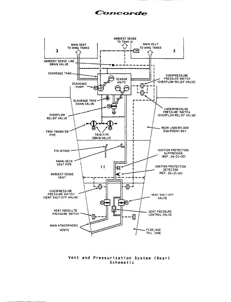
Fuel tank vent and pressurisation
Mr Vortex
Finally as promised, here is a schematic of the AFT part of the fuel vent system. As you can tsee the fin intake pressurises the air space above tank 11, and hence, via the Scavenge Tank air-space, the remaining tanks. (Also you can see the Trim Pipe Drain Vaves you were asking about.
Regards Dude
Quote:
|
Finally, does some one have a schematic or the fuel vent system?
|
Regards Dude
11th Aug 2011, 11:46
permalink Post: 1422
hissinsid
I have to admit, this is one superb image (and a nice high resolution one also) of my old friend Alpha Alpha.
As far as the trip switches to the rear of the captain, not quite sure what you are refering to I'm afraid unless you mean the area on 213 circuit breaker panels? Also located here are the Audio Selector Panel, the emergency windshield de-ice switches (quite hairy really , 200 volts placed straight on the main windshield heating film with no temperature regulation or overheat protection). As well we also have the lighting controls for the panel and a fully deployed observer's coffee cup holder.
As far as the bits either side of the E/O's table, well there is a fair bit, but I'll do my best:
To the left we have the engine start panel, the air conditioning test panel (also encompassing the fuel vent suppression test and indication and gauge limit reset button) and door warning panel. Below these panels are the mode selector panels for the Inertial Navigation Systems and the artificial feel test and Ram Air Turbine control panels. At the very bottom we have the air intake test and diagnostic panels, as well as the anti ice indicator panel. The E/O's Audio Selector Panel and last of all we have the radiation meter and landing gear fault annunciator. (This item is not fitted to aircraft G-BOAG or any Air France aircraft).
To the right we have the Aircraft Integrated Data System panel and immediately below that the compass control panel. (Concorde was one of the very last aircraft to have a magnetic heading reference system, modern aircraft synthesise magnetic heading against true heading and geographic position). Below that we have the oxygen indication panel and to the top right of the section we have the engine and fire test panel. Immediately below this we have the automatic test panel for Automatic Flight Control System and below this the smoke detector test panel. Below this we have the cockpit voice recorder panel and last of all the current monitor panel for the intake secondary air doors.
WHEW!! I hope this helps but if not please ask away.
Regards
Dude
Last edited by M2dude; 13th Aug 2011 at 00:43 .