19th Aug 2010, 00:22
permalink Post: 23
Biggles78
I must admit, it seems excessive carrying 10,000kg in a trim tank, but this fuel system really was a study in elegance. Every single drop of fuel carried was usable by the engines, and the Mach Trimming was so good that you could fine-tune the process so as to achieve the minimum drag configuration for the aircraft of 1/2 degree down elevon in supersonic cruise. One rather amusing point about the fuel Mach trimming; the airworthiness authorities insisted that the aircraft also had a conventional Mach trimmer built into the electric pitch trim system. As the aircraft was mostly flown on autopliot, assuming the fuel trimming was being done correctly (it always was), the auto-trim would wind off this Mach trimming as it was applied, the net result of course being no change to the pitch demand. This really was a totally superfluous addition to the electric trim system. (If for any reason the aircraft HAD been hand flown during acceleration, the pilot would have to nudge the trim button nose down all the time as the A/C accelerated, in order to to oppose the nose up electric trim input).
The fuel, apart from 'lighting the fires' and trimming the aircraft was also used as a cooling medium for engine and IDG oil, as well as for the hydraulic system also. Where it was used to massive effect, was as a cooling medium for the air conditioning system. Here, at Mach 2 conditions, we needed air to exit the 'packs' (on Concorde these were called 'groups') at around -25 deg's C. By the time this air had travelled through the wing ducting it had risen to a sweltering 0 deg's C, at which temperature it entered the cabin. The astonishing thing is, that the air used for this, HP compressor delivery air, P3, was at around 550 deg's C as it left the engine. The ram air itself, used to cool the Primary and Secondary heat exchangers, had a total temperature anything up to 127 deg's C, and to complete this story, the fuel itself had an average temperature of around 60 deg's C. And surprisingly enough, it was a more or less conventional air conditioning system, using air/air intercoolers, an air cycle machine, with just the addition of the fuel exchanger (between the outlet of the secondary heat exchanger and the ACM turbine) to make it any different in concept to most other air cond' systems.
27th Aug 2010, 22:12
permalink Post: 145
Notfred
Love the lightning story, hadn't heard that one before.
That would have been production series test aircraft G-BBDG, A/C 202 before a purpose built hangar (more shed really) was built to house her, with fin and U/C removed. This aircraft has now been beautifully restored at Brooklands museum.
You are quite correct about the pushback, not having an APU (THAT story again
 ) meant that a one engine in each nacelle pair had to be started on the gate, and the other in each nacelle started after push. Having a symetrical pair started enabled all 3 hydraulic systems, and hence most of the critical systems to be checked puring pushback.
Brake temperatures always had to be monitored; they really could get very hot. If a wheel was still too warm after T/O, then the gear would be left down just a little longer to aid cooling. (Each brake also had an electric cooling fan).
Idle thrust was always a problem in that it was too high; there was a 'lo idle' setting, but depending on the temperature of the day the difference was not that big. You could not just reduce idle some more because of a malady known as rotating stall. This can plague any engine, but the Olympus 593 was particularly susceptible. At very low idle speeds, pockets of air 'rotate' around the first few compressor stages and can completely alter the airflows through the engine. It is important that the engine is always accelerated quickly through this zone on start-up, because serious damage can occur if the engine runs for any period of time in the rotating stall region. If the engine DOES operate in this zone, then the combustion process can even occur in the last few stages of the HP compressor, causing extreme damage. This damage, although malignant, can result in blade failure and the subsequent damage to the combustion chamber and turbine areas. This can occur within a few flights of the event, so just cranking down the idle was never an option.
Love the lightning story, hadn't heard that one before.
Quote:
| I was in the Air Training Corps in Bristol in the late 80s and flew in the Chipmunks based at Filton. Used to see the spare Concorde sitting there outside the hangar. |
Quote:
| And a question of my own - I've heard that the engines were pretty powerful even at ground idle, so powerful that if all 4 were running then a tug would not be able to push her back. Any truth to this? Were just 2 started, pushback and then start the remainder? Also heard that the pilots had to watch the brake temps whilst taxiing out to takeoff - was this also due to the power? |
) meant that a one engine in each nacelle pair had to be started on the gate, and the other in each nacelle started after push. Having a symetrical pair started enabled all 3 hydraulic systems, and hence most of the critical systems to be checked puring pushback.
Brake temperatures always had to be monitored; they really could get very hot. If a wheel was still too warm after T/O, then the gear would be left down just a little longer to aid cooling. (Each brake also had an electric cooling fan).
Idle thrust was always a problem in that it was too high; there was a 'lo idle' setting, but depending on the temperature of the day the difference was not that big. You could not just reduce idle some more because of a malady known as rotating stall. This can plague any engine, but the Olympus 593 was particularly susceptible. At very low idle speeds, pockets of air 'rotate' around the first few compressor stages and can completely alter the airflows through the engine. It is important that the engine is always accelerated quickly through this zone on start-up, because serious damage can occur if the engine runs for any period of time in the rotating stall region. If the engine DOES operate in this zone, then the combustion process can even occur in the last few stages of the HP compressor, causing extreme damage. This damage, although malignant, can result in blade failure and the subsequent damage to the combustion chamber and turbine areas. This can occur within a few flights of the event, so just cranking down the idle was never an option.
5th Sep 2010, 11:56
permalink Post: 217
Capt Chambo
Concorde was, as EXWOK says, could use reverse in flight, on the inboard engines only, and only as far as reverse idle, the mechanism of which was quite complex and did on occasion not do work as advertised. Bear in mind here that the Rolls Royce Olympus 593 was a pure turbojet with no bypass, and so a hot stream reverser only had to be used; the reverser buckets acting directly on the efflux as it did any reverser in the 'old' days. Also the same buckets that were used for reverse were also progressively opened up between Mach 0.55 and wide open at Mach 1.1, this giving a vital control enhancement to the divergencing efflux. The overall effect of this was to give a true overall convergent/divergent nozzle assembly, the ideal for any supersonic aircraft.
As far as inflight reverse goes, the amount of HP compressor delivery air (P3) required to actuate the bucket airmotor in flight at an idle thrust settings, was quite minimal to say the least, and some help was definitely needed here. The moment that inflight reverse was selected (on the inboard engines only remember) the OUTBOARD engines would have their idle N2 automatically increased, and some of THEIR P3 air supply was also automatically ported over (via an isolation valve) to the inboard buckets. This whole process was required in order to give a little added muscle to the bucket airmotors, and give the system a fighting chance. Even this however was still not quite enough, the inboard travelling buckets required minimal air loading on their surface, and so the primary nozzles for the affected engines (the primary nozzle lived just aft of the LP turbine, aft of the reheat assembly) was automatically signalled wide open in order to assist matters here, by reducing gas velocity. One the buckets had reached full reverse the primary nozzle was then signalled full close (this applied for normal ground reverse also) and the automatic increased idle on the outboard engines was cancelled. To enable the described process to occur, provided all four engines were at idle, a solenoid latched button on the F/E's station could be selected. This signalled a circuit that enabled the selection of idle reverse on the inboard engines only, the opening of the P3 isolation valve, the raising of the outboard engine's idle and maximum primary nozzle angle for the outboards as soon as reverse was then selected..
The whole system was just a little fragile here; failure of either the extra air supply, or the raised idle on the 'other' engine was usually enough to stop the process working correctly.
EXWOK
While flying 'up front' I only ever experienced the use of inflight reverse once. (The captain was a bit of an Animal, if you flying guys see what I mean ). I would not say that it felt as if we'd hit a brick wall, as I'd expected the sensation to feel, more like we were flying into the dumped contents of a very large manure truck
 . The whole operation was so slick, we'd dumped the required amount of IAS more or less within a second or two, and normal thrust was immediately selected. As so often happened with you guys, you made it look too easy.
As far as the speed of the airmotor goes, I seem to remember that it was something in the order of 80,000 RPM at max chat; as you say faster (around twice as fast) as the standby horizon motor.
The basic core airmotor (not the whole assembly) was the same Garrett unit used on the P&W JT9 as well as the RB-211.
Dude
Concorde was, as EXWOK says, could use reverse in flight, on the inboard engines only, and only as far as reverse idle, the mechanism of which was quite complex and did on occasion not do work as advertised. Bear in mind here that the Rolls Royce Olympus 593 was a pure turbojet with no bypass, and so a hot stream reverser only had to be used; the reverser buckets acting directly on the efflux as it did any reverser in the 'old' days. Also the same buckets that were used for reverse were also progressively opened up between Mach 0.55 and wide open at Mach 1.1, this giving a vital control enhancement to the divergencing efflux. The overall effect of this was to give a true overall convergent/divergent nozzle assembly, the ideal for any supersonic aircraft.
As far as inflight reverse goes, the amount of HP compressor delivery air (P3) required to actuate the bucket airmotor in flight at an idle thrust settings, was quite minimal to say the least, and some help was definitely needed here. The moment that inflight reverse was selected (on the inboard engines only remember) the OUTBOARD engines would have their idle N2 automatically increased, and some of THEIR P3 air supply was also automatically ported over (via an isolation valve) to the inboard buckets. This whole process was required in order to give a little added muscle to the bucket airmotors, and give the system a fighting chance. Even this however was still not quite enough, the inboard travelling buckets required minimal air loading on their surface, and so the primary nozzles for the affected engines (the primary nozzle lived just aft of the LP turbine, aft of the reheat assembly) was automatically signalled wide open in order to assist matters here, by reducing gas velocity. One the buckets had reached full reverse the primary nozzle was then signalled full close (this applied for normal ground reverse also) and the automatic increased idle on the outboard engines was cancelled. To enable the described process to occur, provided all four engines were at idle, a solenoid latched button on the F/E's station could be selected. This signalled a circuit that enabled the selection of idle reverse on the inboard engines only, the opening of the P3 isolation valve, the raising of the outboard engine's idle and maximum primary nozzle angle for the outboards as soon as reverse was then selected..
The whole system was just a little fragile here; failure of either the extra air supply, or the raised idle on the 'other' engine was usually enough to stop the process working correctly.
EXWOK
While flying 'up front' I only ever experienced the use of inflight reverse once. (The captain was a bit of an Animal, if you flying guys see what I mean
). I would not say that it felt as if we'd hit a brick wall, as I'd expected the sensation to feel, more like we were flying into the dumped contents of a very large manure truck
. The whole operation was so slick, we'd dumped the required amount of IAS more or less within a second or two, and normal thrust was immediately selected. As so often happened with you guys, you made it look too easy.
As far as the speed of the airmotor goes, I seem to remember that it was something in the order of 80,000 RPM at max chat; as you say faster (around twice as fast) as the standby horizon motor.
The basic core airmotor (not the whole assembly) was the same Garrett unit used on the P&W JT9 as well as the RB-211.
Dude
Last edited by M2dude; 5th Sep 2010 at 13:25 .
24th Oct 2010, 22:18
permalink Post: 602
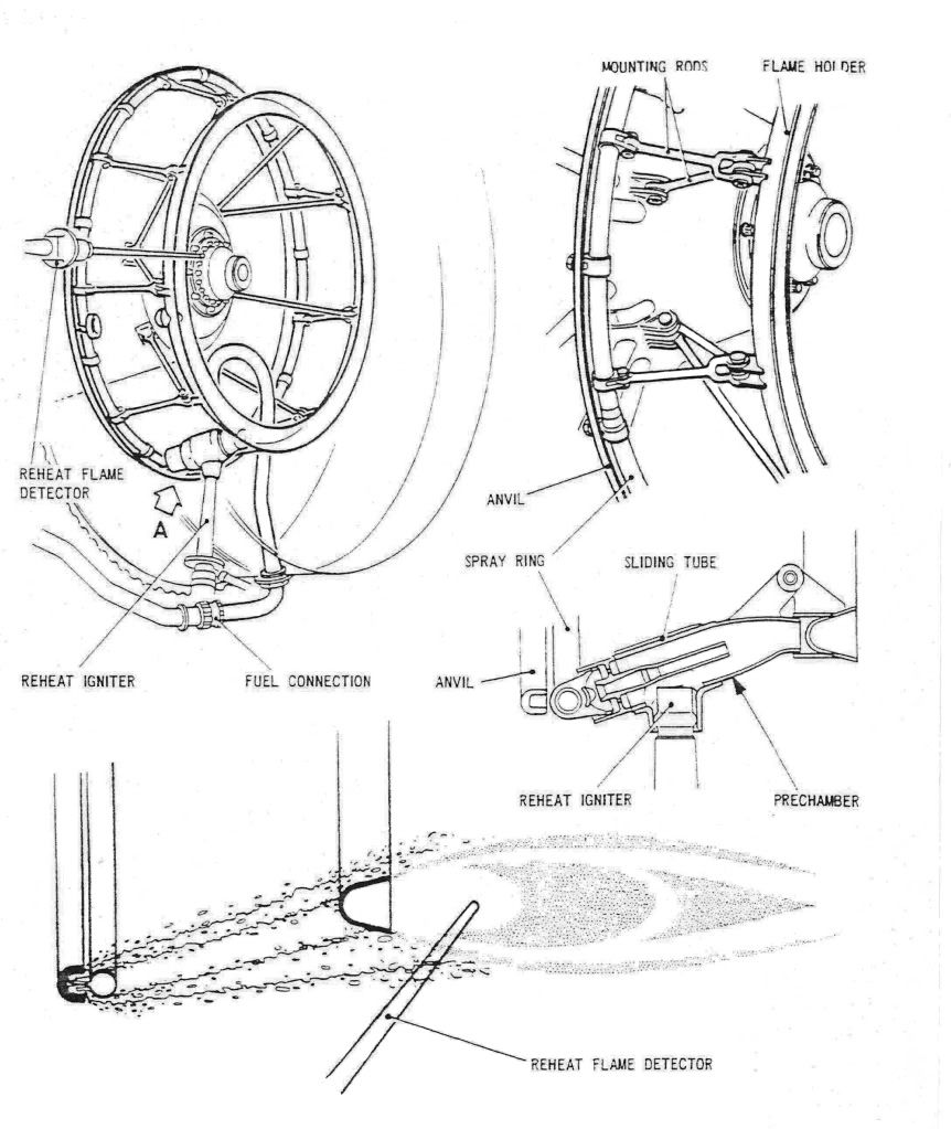
Consider it done Feathers.

As promised, here are a few diagrams of the Concorde reheat (afterburner, for our American friends) system. The ORIGINAL design was done by SNECMA, but due to them getting into all sorts of trouble with the fuel injection system and flame stabilisation, Rolls Royce baled them out, and it became a Rolls Royce/SNECMA design. (The core engine was a 100% Rolls design, with no French input whatsoever. However some engine sub-assembles were manufactured by SNECMA).
The basic way the afterburner worked was by spraying the fuel FORWARDS intially at high pressure, against the jet stram about one inch, until it hit the anvil. . As the fuel strikes the anvil it is blown back by the jet stram and atomises, passing over the of the spray ring and the over the flame holder. The ignition operated by passing 15KV across a dual cylindrical tube, the resulting arc was 'swirlied' into the fuel stream by blowing engine 5th stage HP compressor air into the tube (there were 7 stages in all).
The key to successful ignition was a healthy spark, a good supply of air to the ignitor and accurate scheduling of fuel flow. (This was scheduled against dry engine flow as a funtion of total temperature). The other important factor (as with any afterburner) was correct and rapid operation of the exhaust nozzle. Fortunately, Concorde used it's primary nozzle for control of engine N1 anyway, so adapting this to operate as an afterburning nozzle also was a relative walk in the park, and it operated superbly.
During the light up phase of 3.5 seconds, the fuel ratio is a fixed 0.45 (ie. reheat fuel is 45% of dry fuel). After the light up phase the full scheduling commenced. As far as the FLIGHT RATING figures go (not take-off) the ratios were 0.6 at a TAT of 54 deg's C, falling linearly to 0.3 at 107 deg's C and above. (Remember that Concorde used afterburning really sparingly, just for take-off and then transonic acceleration; cut off at Mach 1.7 altogether.
Dude
28th Oct 2010, 09:19
permalink Post: 622
Quote:
| Forgive me if this has been covered before but did the Concorde have bleed air wing or fin Anti-Icing ? |
Now the leading edges of the intakes and the leading edges of various bits within the intake along with the underside of the wing in front of the the intakes were deiced by a combination of continuous and cyclic electrically heated mats.
All of this electrically heated deicing was infact extened engine deicing so as to ensure that when the ice came off it would be in small enough chunks for the engine to digest without damage. [Another system almost direct from the Bristol Britannia]
The fin nor the rest of the wing had any anti icing system
7th Nov 2010, 01:34
permalink Post: 674
Oh darn it Feathers, if you insist (LOL).

First of all, what is rotating stall? All gas turbine engines are prone to this to some degree or another, the Olympus was particularly prone (so we discovered to our cost). What happens is that extremely LOW figures of N2, small cells of stalled air rotate around the anulus of the early stages of the HP compressor (at approximately half the rotational rpm), resulting in parts of the airflow becoming choked and highly distorted. This often results in the combustion process being disturbed to the extent that combustion instead of occuring in the combustion chamber, occurs in the turbine itself. This of course results in massive overheating of the turbine blades and stators (and is what is suspected occured in the #2 engine on G-BOAA in 1991.
To prevent running in rotating stall, the Olympus automatic fuel start schedule would accelerate the engine quickly to around 67% N2 before dropping back to the normal idle figure of around 65% N2. (The stall clearance N2 figure was ambient temperature dependant, the higher the temperature the higher the N2 that was required and hence scheduled by the automatics).
What had happened on G-BOAA was an engine starting/accelerating problem, where the N2 ran at a sub-idle of around 40% N2 for several minutes. This was enough for the malignant effects of rotating stall to take hold, and the resulting turbine blade failure over the Atlantic the following day. In all fairness to everyone involved, none of us, including Rolls Royce realised just how potentially serious this phenonomen was, and salutary lessons were learned by one and all. (The following year Air France had a similar failure; their first and last also).
I flew out to Shannon on a BAC 1-11, that was sent to fly the Concorde passengers back to London. As I and my colleague were coming down the ventral door steps of the 1-11, a chirpy Aer Lingus engineer asks 'have you guys come to fix the broken engine?, there are bits of it lying in the jet pipe'. Now up to now, from the information we'd been given in London, we thought that we were going to be looking at either an intake or engine induced surge, a few systems checks and boroscope inspections and we'd all be on our way, so we naturally thought the Aer Lingus guy was joking. He was most certainly was not; as you looked into the jetpipe (through the secondary nozzle buckets) you could see a large quantity of metal debris, accompanied by a strong smell of burnt oil. I remember this day well, it was the day that the first Gulf war ended; how ironic.
The aircraft departed on three engines, flown by a management crew late the following day, my colleague and I returned to London by Aer Lingus one day later. (No passengers whatsoever are permitted on ferry flights, even expendable ones like me).
Dude
7th Nov 2010, 21:59
permalink Post: 680
Landroger
Good to see you here again Roger, I'll try my best to give you my take on rotating stall. (I worked very closely with Rolls Royce in the Concorde days, and everything I know about the process is thanks to them). Turbine engine combustion is a precise and delicate affair, particularly during start, and too much or too little fuel can cause severe problems. With rotating stall, the rotating cells of stalled air. if they manage to take 'hold' can cyclically choke the flow into the latter compressor stages (it's the cyclic nature of the cells that is the real problem, hence the 'rotating' stall term). The cells as they 'hit' the compressor blades (the cells are rotating at half shaft speed in the opposite direction of shaft rotation) can cause blade vibration and can also cause minor surges within the engine. The combustion fire literally can burn in the turbine section, but any distortion to the combustion process will result in local overheating, due to poor air/fuel mixing etc. In some engine types, damage can be also be caused to the HP compressor blades (due to vibration) but with the Olympus the main danger was to the turbine blades and stators. It's difficult to relate to any common analogy for this lot I'm afraid Roger.
Rotating stall was avoided in the Olympus by starting the engine with the primary nozzle driven wide open, and controlling two parameters; those being the opening rate of the fuel valve and the rate of rise of exhaust gas temperature. (During the start sequence, once ignition had occured the EGT rise was held to 6 degrees per second, right up until rotating stall clearance at 65% temperature corrected N2 ). So the engine accelerates without let or hinderance right through the danger zone, but was prevented from dipping below 65% temperature corrected N2, where the danger zone starts again. (Absolute minimal idle for the Olympus 593 was set at 61% N2).
I sincerely hope this blurb helps Roger, if not then feel free to ask again or PM me.
Regards
Dude
18th Nov 2010, 00:32
permalink Post: 719
Mr Vortex
First of all, 'welcome aboard'; I'll do my best to answer your queries.
The area of the primary nozzle Aj, was varied for 2 'primary' purposes
:
a) To act as a military type 'reheat' or 'afterburning' nozzle; opening up to control the rise in jet pipe pressure P7, as reheat is in operated.
b) To match the INLET TOTAL TEMPERATURE RELATED (T1) speed of the LP compressor N1 to the HP compressor N2 against a series of schedules, ensuring easch spool is as close as safely possible to its respective surge boundary, (with a constant TET, see below) and therefore at peak efficiency.
Now, in doing this a complex set of variables were in place. As the nozzle is opened there is a REDUCED pressure and temperature drop across the LP turbine. This has the effect of enabling a HIGHER N1,as less work is being done by the turbine. Also the change (in this case a decrease) in the temperature drop across the turbine will obviously affect the turbine entry temperature, TET. A closing down of the nozzle would obviously have the opposite effect, with a DECREASE in N1 and an INCREASE in TET.
In practice at a given T1 there was always an ideal N1 versus N2 on the control schedule (known as the E Schedule), the TET staying more or less constant from TAKE-OFF to SUPERSONIC CRUISE!!
As far as noise abatement went; when reheat was cancelled and power reduced after take-off, an E Schedule known as E Flyover was automatically invoked. This had the effect of driving the primary nozzle nearly wide open, reducing both the velocity of the jet efflux and in essence the noise below the aircraft.
The real beauty of this primary nozzle system was that it really did not care if the engine was operating dry or with afterburning ('it' did not even know). P7 was controlled against a varying compressor outlet pressure, the variable being controlled by a needle valve operated by the electronic engine controller. (If this is unclear I can post a diagram here that shows this control in action).
As soon as I receive back the majority of my technical notes that I have out on long-term loan (I've requested their return) I will post a schematic here. But for now; The tanks were vented to atmosphere via tandem vent galleries, the two vents openings being on the left hand side of the tail-cone. At an absolute static pressure of 2.2 PSIA (around 44,000') twin electrically operated vent valves, also in the tail-cone, would automatically close; the tanks now being pressurised via a small NACA duct on the right side of the fin. A tank pressure of around 1.5 PSIG was maintained by the action of a small pneumatic valve at the rear of the aircraft. There was massive protection built in to guard against over-pressure (eg. if a tank over-filled in cruise).
I hope this answers some of your queries
Best Regards
Dude
Quote:
|
1. I've heard that Concorde use the primary nozzle to modulate the noise and the speed of the N1 compressor. How does it work? and does it help to reduce the noise a lot?
2.Another thing about Primary nozzle. If i recall it correctly, the primary nozzle can also use to control the Inlet Turbine temperature. Is that true? How is that work |
The area of the primary nozzle Aj, was varied for 2 'primary' purposes
:
a) To act as a military type 'reheat' or 'afterburning' nozzle; opening up to control the rise in jet pipe pressure P7, as reheat is in operated.
b) To match the INLET TOTAL TEMPERATURE RELATED (T1) speed of the LP compressor N1 to the HP compressor N2 against a series of schedules, ensuring easch spool is as close as safely possible to its respective surge boundary, (with a constant TET, see below) and therefore at peak efficiency.
Now, in doing this a complex set of variables were in place. As the nozzle is opened there is a REDUCED pressure and temperature drop across the LP turbine. This has the effect of enabling a HIGHER N1,as less work is being done by the turbine. Also the change (in this case a decrease) in the temperature drop across the turbine will obviously affect the turbine entry temperature, TET. A closing down of the nozzle would obviously have the opposite effect, with a DECREASE in N1 and an INCREASE in TET.
In practice at a given T1 there was always an ideal N1 versus N2 on the control schedule (known as the E Schedule), the TET staying more or less constant from TAKE-OFF to SUPERSONIC CRUISE!!
As far as noise abatement went; when reheat was cancelled and power reduced after take-off, an E Schedule known as E Flyover was automatically invoked. This had the effect of driving the primary nozzle nearly wide open, reducing both the velocity of the jet efflux and in essence the noise below the aircraft.
The real beauty of this primary nozzle system was that it really did not care if the engine was operating dry or with afterburning ('it' did not even know). P7 was controlled against a varying compressor outlet pressure, the variable being controlled by a needle valve operated by the electronic engine controller. (If this is unclear I can post a diagram here that shows this control in action).
Quote:
3.Finally, does some one have a schematic or the fuel vent system?

|
I hope this answers some of your queries
Best Regards
Dude