12th Sep 2010, 08:57
permalink Post: 326
Hi again Stilton. We really need one of the flying folk to answer this one fully, I am not sure what drill there was for this scenario, but I'm sure there was one. The Concorde flying manual had a drill for everything, from a four engine flame out at Mach 2 to a blocked toilet (ok, maybe not the loo thing ), and one of my winged friends EXWOK, Bellerophon,
SEO
Brit312 would remember one.
As far as your point about moving the CG further aft; you never had oodles of fuel to play with , and I'm sure that the guys will mention about handling the aircraft on approach with the CG too far aft. (After landing four tonnes of fuel were transferred from Tanks 5 & 7 into the empty fwd Trim Tank 9, 'to aid ground stability'. ie, help stop the aircraft from trying to sit on it's rear end as the passengers got off).
As far as your visor query goes, well the visor is either up, or retracted into the nose. The nose itself (which I suspect is what you are really referring to) would already be at the fully down 12 1/2 degree setting for landing anyway.
Oh, and back to the ground stability issue, was Concorde ever sat on it's tail by accident? Oh yes, just once to my knowledge. In May 1977, aircraft G-BOAA was returned to Filton for some modifications that were required, and part of these 'mods' was some improvements to the main trim-transfer pipes connecting the three trim transfer tanks 9, 10 & 11, as well as the trim tanks 5 & 7. Now the flow into tank 11 (the rear tank) had to be checked, but there was insufficient fuel at the front of the aircraft for stability. This shortcoming was passed on to the BAe manager in charge of everything, who stuffily refused to listen, and INSISTED that these transfer checks were carried out, 'do as I tell you, I am the manager here'. The man's sole concession to any sort of common sense was to allow a BAe employee to sit on the flight deck 'and watch the CG indicator', what the point of this was, well your guess is as good as mine. The name of the guy sitting on the flight deck was... John Thomas. (Hilarious I know, but true). So in goes the fuel, and in a very short period of time, John Thomas notices that the roof of the Filton assembly hangar seems to be slowly getting closer, and closer, and BANG!! The aircraft nose is high into the roof section of the hangar, but fortunately because the hangar is so huge, the nose did not hit anything, it was just stuck up there, complete with a very worried/terrified John Thomas who is sitting terrified in the captain's seat, staring at the hangar roof. The rear of the aircraft however was not so lucky. The right hand inner elevon came down on top of a hydraulic rig, damaging the elevon badly, as well as FLATTENING the rig. The opened #3 engine bay door came down on some large access steps, tearing the corner of the door. (not much left of the steps either). The rear fuselage, in the area of the hydraulic tanks, was holed quite badly by some access staging, entire spectacle coming to a very 'grinding' halt.
So now we have this Concorde G-BOAA, due to be returned to BA the following day, sat down on top of a lot of equipment, it's nose high in the air with a terrified John Thomas requiring a change of underwear. (The brilliant manager of course was nowhere to be seen). The aircraft was eventually returned to it's rightful attitude by someone WITH some sense instructing Mr Thomas on how to slowly, a little at a time, pump the fuel from Tank 11 forward into Tank 9.
And was OAA returned to BA the following day? errr no. The best skin repair man that BAe had to offer was sent from Weybridge to sort out the holes in the rear fuselage (he did an amazing job) and the crunched bits of aeroplane were repaired or replaced. OAA flew back to Heathrow four short (??) days later.
Dude
As far as your point about moving the CG further aft; you never had oodles of fuel to play with , and I'm sure that the guys will mention about handling the aircraft on approach with the CG too far aft. (After landing four tonnes of fuel were transferred from Tanks 5 & 7 into the empty fwd Trim Tank 9, 'to aid ground stability'. ie, help stop the aircraft from trying to sit on it's rear end as the passengers got off).
As far as your visor query goes, well the visor is either up, or retracted into the nose. The nose itself (which I suspect is what you are really referring to) would already be at the fully down 12 1/2 degree setting for landing anyway.
Oh, and back to the ground stability issue, was Concorde ever sat on it's tail by accident? Oh yes, just once to my knowledge. In May 1977, aircraft G-BOAA was returned to Filton for some modifications that were required, and part of these 'mods' was some improvements to the main trim-transfer pipes connecting the three trim transfer tanks 9, 10 & 11, as well as the trim tanks 5 & 7. Now the flow into tank 11 (the rear tank) had to be checked, but there was insufficient fuel at the front of the aircraft for stability. This shortcoming was passed on to the BAe manager in charge of everything, who stuffily refused to listen, and INSISTED that these transfer checks were carried out, 'do as I tell you, I am the manager here'. The man's sole concession to any sort of common sense was to allow a BAe employee to sit on the flight deck 'and watch the CG indicator', what the point of this was, well your guess is as good as mine. The name of the guy sitting on the flight deck was... John Thomas. (Hilarious I know, but true). So in goes the fuel, and in a very short period of time, John Thomas notices that the roof of the Filton assembly hangar seems to be slowly getting closer, and closer, and BANG!! The aircraft nose is high into the roof section of the hangar, but fortunately because the hangar is so huge, the nose did not hit anything, it was just stuck up there, complete with a very worried/terrified John Thomas who is sitting terrified in the captain's seat, staring at the hangar roof. The rear of the aircraft however was not so lucky. The right hand inner elevon came down on top of a hydraulic rig, damaging the elevon badly, as well as FLATTENING the rig. The opened #3 engine bay door came down on some large access steps, tearing the corner of the door. (not much left of the steps either). The rear fuselage, in the area of the hydraulic tanks, was holed quite badly by some access staging, entire spectacle coming to a very 'grinding' halt.
So now we have this Concorde G-BOAA, due to be returned to BA the following day, sat down on top of a lot of equipment, it's nose high in the air with a terrified John Thomas requiring a change of underwear.
(The brilliant manager of course was nowhere to be seen). The aircraft was eventually returned to it's rightful attitude by someone WITH some sense instructing Mr Thomas on how to slowly, a little at a time, pump the fuel from Tank 11 forward into Tank 9.
And was OAA returned to BA the following day? errr no. The best skin repair man that BAe had to offer was sent from Weybridge to sort out the holes in the rear fuselage (he did an amazing job) and the crunched bits of aeroplane were repaired or replaced. OAA flew back to Heathrow four short (??) days later.
Dude
19th Sep 2010, 22:57
permalink Post: 410
Quote:
|
Originally Posted by
atakacs

I have always been of the possibly not substantiated opinion that all was done to make sure she would never fly again.
|
Opinions and remarks like yours really belong on forums like "SCG" or the comments columns of tabloids....
But I'll try to answer you.
The aircraft were "decommissioned".
That means that they were fully prepared as public museum exhibits, rather than being "mothballed", ready to be put back into service.
The purpose was not to make sure they would never fly again, it was to make sure they were safe for the public to visit.
That included draining all fuel, hydraulic liquid, etc.
That meant removing all pyrotechnics, like those in the RAT.
That implied venting and/or removing all high-pressure vessels, such as the emergency slides, fire bottles, oxygen systems, nitrogen tanks.
In the case of the BA aircraft, it also meant removing the electric ground power connections, to avoid incompetent amateurs trying to put ground power back on the aircraft, and start a fire.
Most of these things could have been rectified quite easily. But there was no intent to ever fly any of these aircraft again, so there was no effort made to "mothball" the aircraft, which would have been done quite differently, such as inerting some of the systems, dropping all of the engines, etc. and, far more importantly, keep a maintenance structure in place, not allow public access to any of the aircraft, etc.
Once Airbus relinquished the Type Certificate, that was the end.
Quote:
| ...it would have been possible to nicely package all remaining spares and technical documentation |
You clearly have no idea what that would have been involved.
Just the spares alone... most of them are "lifed", and would regularly need to be either retested and requalified, or would have to be binned and replaced.
Quote:
| .. not mentioning the reckless butchering of many airframes. |
CJ
25th Sep 2010, 17:05
permalink Post: 469
I just finished reading the captivating thread, and I hope you don't mind me dredging up a couple of technical points that were touched on earlier. (Very simple technical points, or they would have gone over my head entirely.)
Early on there was a discussion of sliding hydraulic seals (necessary to allow for thermal expansion of the airplane). It occurred to me that sliding hydraulic seals are nearly as rare as hydraulic cylinders. But that raises an obvious question: what kept the seals from acting like cylinders, and fully extending under pressure?
And then a very picky observation on the discussion about excess moisture evaporating vs. boiling off during flight at temperatures up to 100C. Wouldn't water boil well below 100C at FL 600?
25th Sep 2010, 17:56
permalink Post: 470
Quote:
|
Originally Posted by
Chu Chu
...what kept the (hydraulic) seals from
acting
like (hydraulic) cylinders, and fully extending under pressure?
|
But I would say the basic answers are
- the hydraulic lines at either end of the seal would be clamped down at some point,
- a hydraulic cylinder normally consists of a cylinder and a piston , with the latter of course missing in the seal arrangement.
Quote:
| And then a very picky observation on the discussion about excess moisture evaporating vs. boiling off during flight at temperatures up to 100C. Wouldn't water boil well below 100C at FL 600? |
The end result was of course that most if not all of the accumulated humidity either evaporated or indeed in some places literally 'boiled off', unlike subsonic aircraft.
CJ
25th Sep 2010, 18:33
permalink Post: 471
Let me just explain a little more so you can tell me where I'm going wrong. I've got the seal pictured as two concentric tubes with O-rings between. If the outer tube is the "cylinder," the only difference between the inner tube and a piston is that it's hollow. But assuming no flow, how would the fluid in the "cylinder" "know" it's pressing against pressurized hydraulic fluid in the inner tube and not a solid steel piston?
Of course it would be a pretty small cylinder, little bigger in diameter than they hydraulic line itself. So maybe the answer is just that the restraints on either side are enough to deal with the force generated.
Of course it would be a pretty small cylinder, little bigger in diameter than they hydraulic line itself. So maybe the answer is just that the restraints on either side are enough to deal with the force generated.
Last edited by Chu Chu; 25th Sep 2010 at 18:52 .
25th Sep 2010, 22:03
permalink Post: 472
Chu Chu
,
You're quite right, actually, especially assuming no flow.
"how would the fluid in the "cylinder" "know" it's pressing against pressurized hydraulic fluid in the inner tube and not a solid steel piston? "
The fluid wouldn't "know".. It would be pressing against pressurized hydraulic fluid further down the line.... but at the end, it would finally be pressing against the piston of a hydraulic cylinder of some kind at the end, like the 'cap' in my first scribble.
If nothing was restrained "downstream", indeed everything would be "blown apart".
Of course, that hydraulic cylinder (my 'cap') would be affixed to the structure, so it wouldn't move.
The problem is more like my second scribble.... with a bend in the pipe, and only the final 'cap' fixed, the pipe would continuously flex under pressure.... not a good idea at all, especially when the pressure in the pipe varies, because the 'cap' is not a real 'cap' but something like a PFCU (power flight control unit), with continously varying demand.
So yes, the hydraulic lines are restrained in all the right places, for the hydraulic expansion seals to work correctly without setting up stresses in the lines themselves (except for the pressure acting outwards, of course).
Hope this makes sense to you?
CJ
26th Sep 2010, 06:19
permalink Post: 474
Nice sketches CJ. However the majority of the EXPANSION JOINTS (That's what they were called) were on long linear runs of hydraulic pipes, where the problems of thermal expansion were of course greatest. The expansion joints were one of the biggest leakage problems we ever had; once a seal went things got VERY wet, and the joint had to be replaced. (4000 PSIG can move a lot of fluid).
Dude
Dude
30th Sep 2010, 15:03
permalink Post: 500
I copied this off M2dude's post a couple of days ago, and tried to answer it all offline without cheating by looking up the answers elsewhere.
1) How many fuel tanks were there on Concorde?
LOL... 13.
I suppose that, for the same reason there was no row 13 in the cabin, somebody decided to name two of the tanks "5A" and "7A", rather than call the tail trim tank (named no.11) number 13.
Yes, I forgot the scavenge tank.
And since it was "BA Concordes only" I didn't want to add the hydrazine tank on the two preprod and the two certification aircraft.
2) How many seats were there?
Good question.
As Nick asked, which seats?
Nominally there were 100 pax seats in the cabin, although originally up to 127 were certified.
Five (three plus two jump seats) in the cockpit.
Cabin seats for the cabin crew.... I honestly don't know. Seven?
Wrong twice... six cabin crew seats, AND I forgot to count the loos!
3) At what approximate altitude and KNOTS EAS was Mach 2 achieved?
Roughly, FL500 and 530 kts.
But not being a pilot I had to check an instant on my flight envelope crib sheet, which I have at hand all the time.....
It seemed pointless to be TOO precise, because that assumed ISA and creeping exactly up the right edge of the envelope.
4) Only one BA Concorde had three different registrations, what was it?
Without looking it up, no idea. My guess is G-BOAF, with a white-tail reg, a "British" reg, and a pseudo-American reg.
IIRC, G-BOAG never had a pseudo-American reg, but I'm not sure without looking it up.
Brain not completely addled, then.
5) What was the maximum permitted altitude in passenger service?
FL600, as certified.
6) How many wheels on the aircraft?
Twelve, if you count the two Spitfire wheels at the back
7) How many flying control modes were there?
Four. Blue, green, mechanical and ... what did we call it? Control jam, CWS?
Ah, thanks, Emergency Flight Control. I always considered it as a separate mode, even if it was virtually never used.
8) How many positions of nose droop were there?
Four. 0\xb0, 5\xb0, 12.5\xb0 and 17.5\xb0 (the latter only on the prototypes, and purely mechanically, after removing a stop, on the other aircraft).
9) What was the first microprocessor application on the aircraft?
No idea... you (M2dude) mentioned a Plessey data acquisition system?
It was after "my time"...
10) How many main electrical sources were there?
Again, not sure... You're presumably are talking about primary sources.
There was an AC constant-drive generator on each engine.
Then there were two DC batteries.
And IIRC there was an AC generator running off the RAT hydraulic generator when pillar came to post.
Reading M2dude's answer, I suppose the emergency generator just ran off the hydraulics, not specifically off the RAT. Far more logical.
Nice one, M2dude!
And certainly not all trivia!
CJ
2nd Oct 2010, 08:45
permalink Post: 508
CRON
I can only speak here from the Concorde ground engineering school that I attended over a total of 13 weeks at Filton in 1980 and 1981; the pilot/flight engineer questions there were I'm sure FAR nastier (and also more operationally specific); we did get to share simulator time though, which was really useful. Like the aircrews, we stayed up in a hotel in Bristol during the week. (I personally had only left BAC, as it was then, for BA at Heathrow in late July 1977, so I was returning to familiar pastures). The exam format would be several dozen multi-choice questions per week/phase; a typical question would go something like:
The Inner Elevon Light, plus 'PFC' red Master Warning is triggered by:
a) The Green Flying ControlComparator
b) The Blue Flying Control Comparator
c) Either Comparator
The correct answer is (b).
Another flying controls question I can remember is:
Outer Elevon Neutralisation is triggered at:
a)Vmo + 10 KTS
b)Vmo + 15 KTS
c)Vmo + 25 KTS
The correct answer here is (c).
The pass mark in these exams was 75%, with penalty marking applied for any wrong answers. I always found the worst part was the fact that the exams were on a Friday afternoon after lunch
Nick Thomas
Hi again Nick, one really for the likes of BRIT312, EXWOK etc, but there was, as was mentioned before, an emergency forward transfer switch in the roof panel above the pilots (F/O's side if I remember correctly). When placed to the emergency poition two electric and two hydraulic fuel pumps for the rear trim tank #11 would start up automatically, as well as the forward tank inlet valves being opened also.
From what you said about the 'lady' being ahead of her time, I would certainly agree with you here; in my view she was generations ahead of everything else.
nomorecatering
The BA simulator that resided at Filton has been re-located to Brooklands Museum, and has been re-activated, but without motion and I'm not sure about full visuals either. I've not seen it myself yet, but I'm told that things have progressed really well with the operation. Obviously it is no longer certified as an active simulator; I'm not sure about the situation in France, perhaps my friend ChristiaanJ can answer that one.
I seem to remember typical loads for LHR-JFK being around 93-96 tonnes, depending on the passenger load and en-route conditions. Full tanks, depending on the SG was around 96 Tonnes. High fuel temperatures in the summer were a major pain; restricting maximum onload due to the low SG.
As far as ground school notes, mine are all out on long term loan (MUST get them back). The ground school are totally priceless and I am sure that there are many complete sets lying around in atticks/bedrooms/garages/loos etc.
Dude
Quote:
| If I may ask - and folk can recall - what would a sample question look like from these exams? |
The Inner Elevon Light, plus 'PFC' red Master Warning is triggered by:
a) The Green Flying ControlComparator
b) The Blue Flying Control Comparator
c) Either Comparator
The correct answer is (b).
Another flying controls question I can remember is:
Outer Elevon Neutralisation is triggered at:
a)Vmo + 10 KTS
b)Vmo + 15 KTS
c)Vmo + 25 KTS
The correct answer here is (c).
The pass mark in these exams was 75%, with penalty marking applied for any wrong answers. I always found the worst part was the fact that the exams were on a Friday afternoon after lunch
Nick Thomas
Quote:
| So I have been wondering if there were any special procedures for managing the CofG in a rapid descent especially as there could also be many other factors needing the crews attention? |
From what you said about the 'lady' being ahead of her time, I would certainly agree with you here; in my view she was generations ahead of everything else.
nomorecatering
Quote:
| Are there any concorde simulators that are still working and retain their certification? |
Quote:
| Regarding LHR JFK routes. What was the avarage fuel load and how close to full tanks was it. |
As far as ground school notes, mine are all out on long term loan (MUST get them back). The ground school are totally priceless and I am sure that there are many complete sets lying around in atticks/bedrooms/garages/loos etc.
Dude
Last edited by M2dude; 2nd Oct 2010 at 13:40 .
27th Oct 2010, 22:33
permalink Post: 616
Mike-Bracknell
It is not nonsense, and you are quite at liberty to post here. Wow, that's still quite a question though Mike. There are two TECHNICAL issues that overshadow all others, namely airframe corrosion and hydraulic system deterioration. Unfortunately none of the BA aircraft were stored inside from the outset, so we have a real issue here as far as corrosion goes, plus all the hydraulic systems were drained, resulting in seal drying out and probable moisture ingress into the 3 systems. But given sufficient funds (and assuming you find an organisation to take over design responsibility from Airbus;
ironic when you consider that without Concorde there would almost certainly have been no such organisation
) there is still no technical reason why the problems (and there are dozens of other problems to consider) could not be overcome, the money side of things is another matter
Looking first at the French fleet, the main candidate for restoration to flight status would be F-BTSD at Le Bourget. Not only has this aircraft been lovingly cared for and stored INSIDE, but the aircraft has had several systems (including the Green hydraulic system) powered and reservoirs not drained.
The British story is less clear; G-BOAA in East Fortune was effectively killed when the wings were cut off for transportation, so that one is out of the question. G-BOAB, the last and only Concorde at LHR has been left to rot outside, in fact holes were even drill in the fuselage to drain water, so this one is a no no too. G-BOAC at Manchester, now the oldest surviving production aircraft was initially stored outside, but now resides in a purpose built exhibition 'hangar'. Now she COULD be a potential candidate for consideration; when I last saw her just over a year ago she was absolutely pristine; a testament to the team that have been caring for her there. G-BOAD, stored next to the USS Intrepid in New York, we can probably forget, due to having been exposed to 7 years worth of salt water corrosion from the Hudson River. (Also, while she was temporarily stored in New Jersey a couple of years ago, some IDIOT in a truck bent the whole nose section when he hit her. The radome was smashed (replaced with a rather clever fibreglass fabrication) and the nose straightened with a blow-torch and hammer (I am not joking!!). G-BOAE at Grantley Adams airport in Barbados has been stored under cover for much of the time; provided she has not suffered too much from the wam damp atmosphere of Barbados, well she could be a potential candiitate too. G-BOAF in Filton, well PROVIDED she is still OK after her 'removal from public view' experience could also be a potential candidate also. And finally, G-BOAG in Seattle; well she had been left outside, right next to a highway (and close to a truck stop too). She did not look too good the last time I saw her; the undercarriage barrels werer all brown and discoloured and the paintwork was completely dull and matte. (She had a new paint job not too long before retirement too). So out of the 'BA Seven', I PERSONALLY would go for G-BOAF, G-BOAC or G-BOAG.
As I have said often here before, it is EXTREMELY unlikely that what you, Mike, suggest will ever happen, but in spite of what others might say, IT IS NOT IMPOSSIBLE. My own gut feeling is a resounding 'no', but I could be wrong, . (And NO ONE would be happier than I if I am wrong; I was with the BA aircraft through construction, flight testing and the entire service life with BA).
As for the cost? It really is a case of 'how long is a piece of string', but for 2 aircraft we could be looking in excess of $100 or more, who knows?
But as the Everly Brothers used to sing 'All I have to do is dream.'
Keep posting Mike.
Dude
.
Quote:
| IF funding were secured to get 1 Concorde from each fleet into the air again, which one out of each fleet would be the easiest to return to service, given what has gone on since retirement? Also, a subpoint, does anyone have any finger-in-the-air figures as to how much cost it would take and whether there's any fundamental issues that would need to be sorted aside from the airworthiness certificate etc. |
Looking first at the French fleet, the main candidate for restoration to flight status would be F-BTSD at Le Bourget. Not only has this aircraft been lovingly cared for and stored INSIDE, but the aircraft has had several systems (including the Green hydraulic system) powered and reservoirs not drained.
The British story is less clear; G-BOAA in East Fortune was effectively killed when the wings were cut off for transportation, so that one is out of the question. G-BOAB, the last and only Concorde at LHR has been left to rot outside, in fact holes were even drill in the fuselage to drain water, so this one is a no no too. G-BOAC at Manchester, now the oldest surviving production aircraft was initially stored outside, but now resides in a purpose built exhibition 'hangar'. Now she COULD be a potential candidate for consideration; when I last saw her just over a year ago she was absolutely pristine; a testament to the team that have been caring for her there. G-BOAD, stored next to the USS Intrepid in New York, we can probably forget, due to having been exposed to 7 years worth of salt water corrosion from the Hudson River. (Also, while she was temporarily stored in New Jersey a couple of years ago, some IDIOT in a truck bent the whole nose section when he hit her. The radome was smashed (replaced with a rather clever fibreglass fabrication) and the nose straightened with a blow-torch and hammer (I am not joking!!). G-BOAE at Grantley Adams airport in Barbados has been stored under cover for much of the time; provided she has not suffered too much from the wam damp atmosphere of Barbados, well she could be a potential candiitate too. G-BOAF in Filton, well PROVIDED she is still OK after her 'removal from public view' experience could also be a potential candidate also. And finally, G-BOAG in Seattle; well she had been left outside, right next to a highway (and close to a truck stop too). She did not look too good the last time I saw her; the undercarriage barrels werer all brown and discoloured and the paintwork was completely dull and matte. (She had a new paint job not too long before retirement too). So out of the 'BA Seven', I PERSONALLY would go for G-BOAF, G-BOAC or G-BOAG.
As I have said often here before, it is EXTREMELY unlikely that what you, Mike, suggest will ever happen, but in spite of what others might say, IT IS NOT IMPOSSIBLE. My own gut feeling is a resounding 'no', but I could be wrong, . (And NO ONE would be happier than I if I am wrong; I was with the BA aircraft through construction, flight testing and the entire service life with BA).
As for the cost? It really is a case of 'how long is a piece of string', but for 2 aircraft we could be looking in excess of $100 or more, who knows?
But as the Everly Brothers used to sing 'All I have to do is dream.'
Keep posting Mike.
Dude
.
29th Oct 2010, 19:13
permalink Post: 635
Brit312
mm I guess they were not to blame for flying for over one hour with a red throttle light on (the engine is under no electronic control), resulting in the severe engine overspeed (N1 overspeed protection amplifier already disabled) and the subsequent scrapping (on the orders of Rolls Royce) of the entire rotating assembly of the engine. Or for omitting TWO intake trunnion blocks during a ramp actuator replacement, and then the E/O continually and cyclically operating the intake lane selector switch, following a spill door runaway, until he manages a double engine surge and near destruction of the 'forgotton parts' intake and engine also. I suppose they are not to blame for the experimental tripping of the LPOG circuit breaker by the E/O, during an engine power mismatch, resulting in serious damage to the engine and intake due to the resulting massive over-fueling surge. I suppose again, that they were not to blame for ignoring
for over 6 months
a simple electrical load defect, eventually resulting in a not too minor fire in the electronics racks that had to be extinguished by the crew with extinguishers. And yet again, I suppose they are not to blame for putting skydrol into Concorde hydraulics systems, almost resulting in the loss of the aircraft, as well as a 9 month grounding while all of the hydraulic components were replaced. And it was not Air France that hammered Fox Delta twice into the runway at Dacca, resulting in so much airframe distortion that the aircraft performance was seriously compromised (and eventually broken up). And of course they were not responsible for the technical and operational failures, including the (forgotton
AGAIN
) missing spacer and overweight take-off etc.) on 25th July 2000. Silly me.
And although I might have said 'precautionary engine shut-down', we are talking about a quite an eventful episode here indeed, you can NOT excuse the further mistakes made on that day, 'just because they are poor old Air France. With the greatest of respect Brit, there are 3 crew members on that flight deck, do you not think that the loss of over over 5 tonnes of fuel over a period of time might just be noticed????? The subsonic 3 engined leg was carried out for quite a time before it computed to them that they were still losing fuel. There is no excuse for flying with your eyes closed, I'm sorry.
For goodness sake, this is probably the biggest single episode that was behind the demise of Concorde, poor Air France my eye!!!
Dude
Quote:
|
1] It seems to me thet poor old Air France are blamed when
1] They deviate from the checklist as was suggested in the crash OR 2] Stick to the checklist as in this case |
And although I might have said 'precautionary engine shut-down', we are talking about a quite an eventful episode here indeed, you can NOT excuse the further mistakes made on that day, 'just because they are poor old Air France. With the greatest of respect Brit, there are 3 crew members on that flight deck, do you not think that the loss of over over 5 tonnes of fuel over a period of time might just be noticed????? The subsonic 3 engined leg was carried out for quite a time before it computed to them that they were still losing fuel. There is no excuse for flying with your eyes closed, I'm sorry.
For goodness sake, this is probably the biggest single episode that was behind the demise of Concorde, poor Air France my eye!!!
Dude
Last edited by M2dude; 29th Oct 2010 at 22:55 . Reason: more spelling :-(
10th Nov 2010, 15:43
permalink Post: 694
Quote:
|
Originally Posted by
Biggles78
All due respect but this is the CONCORDE thread and it would be really nice if it could stay as such.
|
Quote:
|
LandLady said in a post many moons ago that there was a pool of some 240 "Concorde Ambassadors" (sorry but CC and FAs don't sound right for this aeroplane) for Her. What was the numbers of Captains, First Officers and the all important Flight Engineers (sucking up to M2 with that one
)
|
Quote:
I looked at the photos posted by a thoughtful member in an earlier post and wonder how former crew felt looking at them. The photos give the impression that you could kick the tyres and light the fires and they would be once again gracing the skies. Obviously they are unairworthy BUT the photos project a different image.

|
As an example, F-BVFC at Toulouse, which was the last one to remain at least taxyable, now has some patches of corrosion starting to show, when you know where to look. Not to mention the nasty smell of damp and mould in the cockpit which bodes no good for what's going on underneath the floor.
And even F-BTSD, kept "live" to some extent at Le Bourget, leaks some hydraulic fluid (like all Concordes did on the ground), so it's easy to imagine the dried-out hydraulic and fuel seals on the other museum aircraft.
And yes, that's kitty litter...
The composite material of the floor and the hydraulic fluid don't agree too well.
Quote:
| Final one for this post. If She was still flying, do you still think that BA (sorry but going to ignore AF on this one) would have sufficient patronage to keep Her as a going and profitable concern? |
CJ
Last edited by ChristiaanJ; 14th Nov 2010 at 11:32 . Reason: typo
21st Nov 2010, 15:37
permalink Post: 751
Mr Vortex
An ejection was recommended because it was possible, not that was necessarily impossible to land a Draken dead stick. F-16s have done a number of them, I witnessed one at KTPA. There was a video of the HUD view of one at NAS Glenview, IL.
To your question, it would depend on distance to go to the airport, glide ratio (high but probably not terribly worse than any conventional airliner) and most importantly the capability of the RAT providing hydraulic power.
M2dude , any idea of the min IAS for the RAT to provide the juice and hydraulics? Would it be as low as Vapp minus some margin?
GF
11th Dec 2010, 22:17
permalink Post: 856
Hi Guys, quite a few little points here, so here's my angle(s):
Pedalz
Ooo yes. The biggest problems we ever had associated with the ramps themselves were wear in the seals at the sides of the forward ramp. Even a few thou' over the maximum allowable side gap was enough to make the intake unstable and susceptible to surging. (It is quite interesting that the rear ramp side gaps were not in the least bit critical, and if Concorde intake development had continued, the rear ramps were going to be deleted altogether). Other failure factors were control unit malfuntions, rapid sensor drift; all of these causing either ramp/spill door drift or runaway. Primary nozzle misbehaviour could also result in intake surges. Having said all that, the monitoring of the intake system was truly superb, and surface runaways, themselves quite rare, would usually be picked up by the control system monitors causing either a lane switch or if that did not work, a total 'red light' failure with the surfaces frozen. No surge was treated as 'just one of those things', and much midnight oil was burned and hair pulled out (so that's what happened to mine
 ) to try and find the cause of the surge.
My friend EXWOK perfectly answered the intake hydraulics allocations.
EXWOK was right on the ball here as usual, in fact above Mach 1.6 an interactive surge was more or less guaranteed. The cause of interactive surge had nothing to do with the wing leading edge position, but to the radially generated distortion field coming out of the FRONT of the surging intake, severely distorting the adjascent intakes airflow. It mattered not if the originating surge was an inboard or an outboard intake, the other guy would always go also, above Mach 1.6.
You might want to take a look at 'When Intakes Go Wrong Part 1:
Concorde engine intake "Thrust"
and Parts 2 & 3:
Concorde engine intake "Thrust"
Not to mention Part 3:
dixi188
I can never recall this particular event happening with BA , certainly not as a result of a ramp failure. Although in the near 28 years of operation we had quite a few SNN diversions, none that I can ever recall were as the result of a ramp structural failure. The two major SNN diversions that I can recall were G-BOAF in the early 80s when an LP1 blade failed and resulted in a totally wrecked engine (although a completely contained failure) and G-BOAA in 1991, with another wrecked engine due to running in rotating stall. (Both of these events were covered previously in our thread). ChristiaanJ has mentioned quite rightly the event with A/C 001 spitting a ramp out, and Air France had a ramp failure going into JFK. (Covered previously in our thread, due to certain 'human foul ups'). I am not sure, but I think that
this
one in JFK DID require a double engine change in JFK. (Usually from SNN a BA aircraft would be 3 engine ferried back to LHR).
ChristiaanJ
Nope, you are quite right, no more French or British development aircraft ever suffered a ramp linkage failure again. The 001 ramp failure was a salutary lesson to the design team, and the intake assembly became tougher than old boots after that, nomatter WHAT you threw at it.

Due to the lateness of the hour (and me being up at 4 ), that will have to do for now guys.
Best regards to all
Dude
Pedalz
Quote:
were the intake ramps in front of the engines ever known for problems? Especially during supersonic cruise where the airflow through the compressors and position of the ramps was determined by an exacting science which could turn into quite a situation if disturbed.
 Which hydraulic system actuated these ramps?
|
) to try and find the cause of the surge.
My friend EXWOK perfectly answered the intake hydraulics allocations.
Quote:
| Due to the shape of the leading edge and positioning of the intakes themselves, could it be possible that disturbed airflow from a problem ramp or donk could also effect it's outboard neighbour (if I'm right in presuming that only the inboard engine surging etc. could effect the outboard and not vice versa)?[/ |
You might want to take a look at 'When Intakes Go Wrong Part 1:
Concorde engine intake "Thrust"
and Parts 2 & 3:
Concorde engine intake "Thrust"
Not to mention Part 3:
dixi188
Quote:
| A certain CFI (I think) at BA flying club, High Wycombe, who was also F/O on concorde, showed me some photographs of an engine that had eaten a piece of intake ramp. I think he said that the adjacent engine had surged and a piece of ramp went out the front and down the other engine. This resulted in a double engine failure mid atlantic. They landed in Shannon with very little fuel left. |
ChristiaanJ
Quote:
PS I have no record of any of the British development aircraft ever having lost a ramp, notwithstanding the number of deliberate engine surges they went hrough. But then maybe I wasn't told....

|
Due to the lateness of the hour (and me being up at 4
), that will have to do for now guys.
Best regards to all
Dude
Last edited by M2dude; 12th Dec 2010 at 04:51 . Reason: Adding a bit and correcting another
22nd Dec 2010, 14:50
permalink Post: 941
Quote:
|
Originally Posted by
M2dude
Concorde had triple-axis auto stabilisation, where pilot demands were routed via an AUTOSTAB COMPUTER and summed with any stabilisation demands.
|
Pilot demands in manual flight produced electrical signals corresponding to the control position, which were sent to the 'servo control amplifiers' (eight in all, one per control surface) which in turn commanded the PFCUs (power flying control units) that hydraulically moved the control surfaces.
Autopilot demands directly moved the pilot's controls (stick and rudder) via hydraulic cylinders (the 'relay jacks') so that the same signals as in manual flight then went to the servo control amplifiers.
The purpose of the autostab was to provide proper dynamic stability over the full flight envelope. The aircraft could be flown without autostab, but over some of the speed range it was only marginally stable.
The electrical signals from the autostab computing were fed directly into the servo control amplifiers, so there was no feedback to the pilot's controls, unlike the autopilot demands.
There was occasional confusion about exactly what did what and how and where.... because the servo control amplifiers - although a function independent of the autostab as such - were housed... in the autostab computers.
To complete the tale, this is what those servo control amplifiers look like.
The one of the left is from prototype 002, the one on the right from a production aircraft. To give them scale, the one on the right is about the size of a box of large kitchen/fireplace matches.
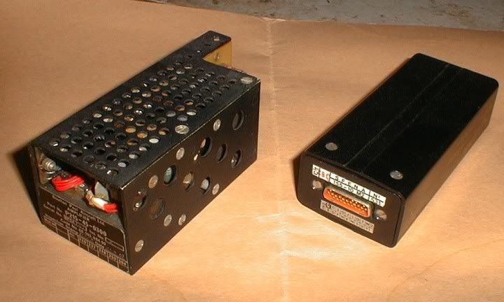
CJ
15th Jan 2011, 21:32
permalink Post: 1106
A quick question for the technical chaps...
I remember that she had 3 channels of signalling for the flight controls - 2 electrical ( 1 main and 1 standby ) with the third being mechanical. How was the mechanical system 'de-coupled' from the electrical channels thus that any movement from the control column was 'ignored' by this channel ? Was it by somehow disabling the hydraulic jack that ultimately connected to the flying control units ? Was this mechanical channel ever used during service ?
Regards,
d
16th Jan 2011, 09:41
permalink Post: 1110
SpeedbirdConcorde
Hi again my friend. To further expand on CliveJ's superb explanation: Mechanical control inputs were fed to each of the 8 Powerd Flying Control Units (PFCUs), but in electronic signalling (either Blue or Green) these inputs were de-clutched at the PFCU input lever. When Fly By Wire' signalling is not available, the mechanical inputs (which as CliveL quite rightly points out) are driven by the Relay Jacks, now are locked to the input lever and can now move the input jack of the PFCU (known as the spool valve) and subsequently cause the PFCU to drive the control surface. (The body of the PFCU moved, the main jacks were attached at each end to structure and so obviously did not move). Hopefully this diagram will help visualising the process a little easier:
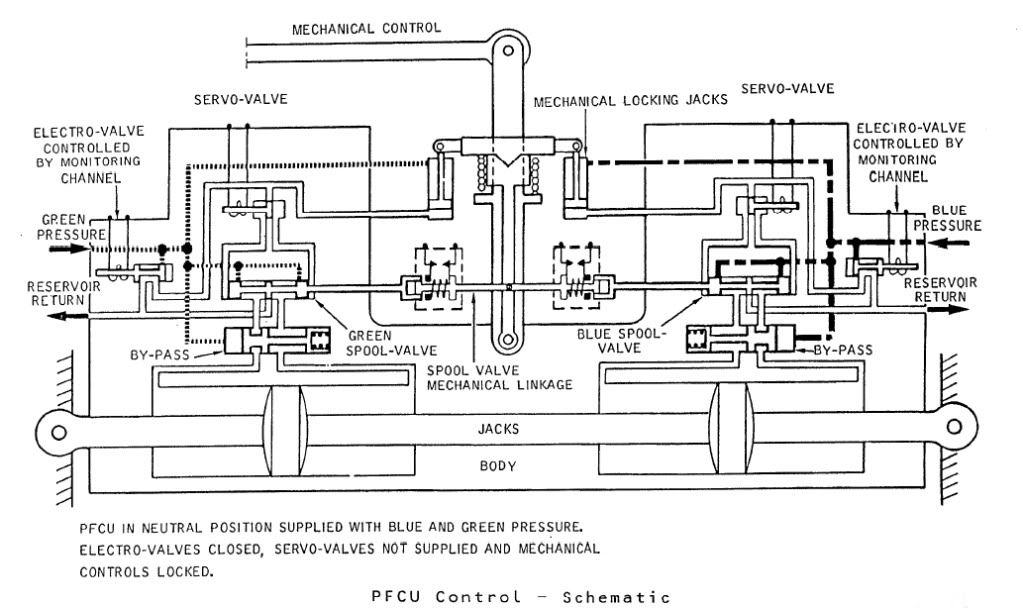
The diagram shows Green & Blue hydraulics supplied but the electro-valves (opened by the respective FBW channel) are both closed. You can see that the mechanical input lever is 'locked' to the PFCU input lever which will drive the SPOOL VALVE directly. When FBW is enabled, either the Blue or Green (never both together) ELECTRO-VALVE are signalled open, the ensuing hydraulic pressure then pushing the input clutch upwards and disengaging the mechanical input. FBW demands are now fed to the respective SERVO VALVE which will hydraulically send the SPOOL VALVE in the desired direction.
The Relay Jacks could be considered to be a little like a PFCU (you had 2 RJs per axix) but instead of the servo valves being driven by the FBW system they were driven by the autopilot and instead of driving a control surface, they drove the control runs. In manual flight the input spool was driven via a mechanical input lever, which would drive the RJ spool a little like Mech' signalling drove the PFCU spool. In A/P mode the mechanical input rod was de-clutched \xe0 la PFCU, but (and here's the clever part) this input was locked to the body of the Relay Jack which when it moved, drove the pilot's control in sympathy. (Control column, yoke or rudder pradals). As the respective control(s) was moved by the Relay Jack, the corresponding FBW position sensor (resolver) would change position and generate the FBW demand. (As the surface moved there was a feedback resolver at PFCU level).
As far as the FBW channels themselves went; there were 2 electronic signalling modes, Blue and Green, sub-divided into 3 groups (Inner Elevons, Outer & Mid Elevons and Rudders). Each group was independently monitored, and a fault in say the Rudder channel alone, would result in the rudders ONLY changing lanes. NOW ( ), The normal control channel was BLUE, and if this failed you would drop the respective channel into GREEN and if this failed you would drop into MECH. The selector switches (1 per group) enabled you to select BLUE/GREEN/MECH in that order. If for some reason you were selected to GREEN, a failure of that signalling lane would not drop you 'up' into BLUE, but into MECH. Your switch would only be in this position if you'd had a problem with BLUE, however you would select this on pushback while you were testing the flying controls, otherwise you spent your whole life selected to BLUE. As far as BA went, I can never remember a time personally when all 3 groups dropped from BLUE to MECH, but very rarely you might get a fault that caused a single group to briefly drop to MECH. Just about one of the very few common mode failures to each of the 3 groups would be a failure of the respective FBW static inverter. This thing, which was rightly monitored up to the hilt, produced a 26 Volt 1800 Hz output. (1800 Hz was chosen as this is not a harmonic of aircraft mainline 400 Hz AC supply)
Best regards
Dude
Hi again my friend. To further expand on CliveJ's superb explanation: Mechanical control inputs were fed to each of the 8 Powerd Flying Control Units (PFCUs), but in electronic signalling (either Blue or Green) these inputs were de-clutched at the PFCU input lever. When Fly By Wire' signalling is not available, the mechanical inputs (which as CliveL quite rightly points out) are driven by the Relay Jacks, now are locked to the input lever and can now move the input jack of the PFCU (known as the spool valve) and subsequently cause the PFCU to drive the control surface. (The body of the PFCU moved, the main jacks were attached at each end to structure and so obviously did not move). Hopefully this diagram will help visualising the process a little easier:
The diagram shows Green & Blue hydraulics supplied but the electro-valves (opened by the respective FBW channel) are both closed. You can see that the mechanical input lever is 'locked' to the PFCU input lever which will drive the SPOOL VALVE directly. When FBW is enabled, either the Blue or Green (never both together) ELECTRO-VALVE are signalled open, the ensuing hydraulic pressure then pushing the input clutch upwards and disengaging the mechanical input. FBW demands are now fed to the respective SERVO VALVE which will hydraulically send the SPOOL VALVE in the desired direction.
The Relay Jacks could be considered to be a little like a PFCU (you had 2 RJs per axix) but instead of the servo valves being driven by the FBW system they were driven by the autopilot and instead of driving a control surface, they drove the control runs. In manual flight the input spool was driven via a mechanical input lever, which would drive the RJ spool a little like Mech' signalling drove the PFCU spool. In A/P mode the mechanical input rod was de-clutched \xe0 la PFCU, but (and here's the clever part) this input was locked to the body of the Relay Jack which when it moved, drove the pilot's control in sympathy. (Control column, yoke or rudder pradals). As the respective control(s) was moved by the Relay Jack, the corresponding FBW position sensor (resolver) would change position and generate the FBW demand. (As the surface moved there was a feedback resolver at PFCU level).
As far as the FBW channels themselves went; there were 2 electronic signalling modes, Blue and Green, sub-divided into 3 groups (Inner Elevons, Outer & Mid Elevons and Rudders). Each group was independently monitored, and a fault in say the Rudder channel alone, would result in the rudders ONLY changing lanes. NOW ( ), The normal control channel was BLUE, and if this failed you would drop the respective channel into GREEN and if this failed you would drop into MECH. The selector switches (1 per group) enabled you to select BLUE/GREEN/MECH in that order. If for some reason you were selected to GREEN, a failure of that signalling lane would not drop you 'up' into BLUE, but into MECH. Your switch would only be in this position if you'd had a problem with BLUE, however you would select this on pushback while you were testing the flying controls, otherwise you spent your whole life selected to BLUE. As far as BA went, I can never remember a time personally when all 3 groups dropped from BLUE to MECH, but very rarely you might get a fault that caused a single group to briefly drop to MECH. Just about one of the very few common mode failures to each of the 3 groups would be a failure of the respective FBW static inverter. This thing, which was rightly monitored up to the hilt, produced a 26 Volt 1800 Hz output. (1800 Hz was chosen as this is not a harmonic of aircraft mainline 400 Hz AC supply)
Best regards
Dude
Last edited by M2dude; 16th Jan 2011 at 12:10 . Reason: Clarity; Oh for clarity
31st Jan 2011, 09:27
permalink Post: 1166
Landroger
Actually it was a great and moving experience Roger. All the people at the function were BA 'Concorde family', so the noise we made that evening was certainly sufficient. It sounds weird I know, but it was almost as if OAC was entering the spirit of the occasion. (And the aircraft was open for us to take photos, reminisce and quite honestly to help remind us all that something really wonderful was now missing from our lives). The aircraft is in such good general condition that she never really seems 'dead' at all
howiehowie93
Nothing missing here Howie. On the RIGHT HAND engines, ie. 2 & 4, Concorde had 2 hydraulic pumps, but on 1 & 3 engines there was only a single pump. What you can see is the spare gearbox provision for the extra YELLOW pump, right next to the IDG. (You can see the pipes coming from the GREEN hydraulic pump in the forward face of the gearbox, immediately forward of the 'blank').
Best regards
Dude
Quote:
| Oh and something that your photograph put in mind. It must be very seldom that even a parked aircraft is actually quiet. Being under AC like that must have been a bit un-nerving for someone so used to being next to Concorde, because she must be virtually silent? |
howiehowie93
Quote:
| is there something missing dead centre of the picture ?? to the Left of what I presume is a an FCU on the Gearbox? Looks to be a V-Band clamp still there hanging on the pad ?? |
Best regards
Dude
12th Mar 2011, 21:49
permalink Post: 1239
The engine starting sequence was also in airline operation 3-4-2-1. At the gate the altered sequence was 3-2 prior the pushback and 4-1 after due to safety reasons for ground crew and for noise restrictions at some airport stands.
Brit312 explained in post #140:
I must admit that I am no expert (not yet
 ), but it seems both sequences follow the logic to feed the blue hydraulic by engine#3 first, then one of the two yellow systems (2 or 4) and the green hydraulic (engines 1&2) which supplies power to some more services than the blue (droop nose and visor, landing gear, main wheel brakes with anti-skid and nosewheel steering).
Well, I hope, this was not a stupid answer before I took a chance for a nonstupid question
- but I am so exited about this thread and just want a little bit to give back!
Thanks for the probably best thing ever I have found in the internet. Thank you M2dude, Brit312, ChristiaanJ, Exwok, Bellerophon, Landlady et al.!
Brit312 explained in post #140:
Quote:
|
Yes we always started just the two inboard engines prior to push back and the outers when the push back was complete. This was for a number of reasons, but I do seem to remember it was not unheard of to break the tow bar shear pin on the initial push, so the less power the better
Remember that Concorde had no APU and no across the ship ducting for stating engines, therefore prior to push an air start unit was plugged into each pair of engines and the inboard engines would be started. This allowed, after push back, air from each inboard engine to be used to start it's outboard engine. The other good reason for starting the inboards prior to push was that with no APU the cabin temp would rise quite quickly [specially in places like Bahrain in summer] and never mind the passengers comfort, but some of M2dude and ChristiaanJ fancy electronic equipment was very temp sensitive , especially those intake control units down the rear galley. With Two engines running we could use their bleed air to at least try and hold the cabin air temp during the push back |
), but it seems both sequences follow the logic to feed the blue hydraulic by engine#3 first, then one of the two yellow systems (2 or 4) and the green hydraulic (engines 1&2) which supplies power to some more services than the blue (droop nose and visor, landing gear, main wheel brakes with anti-skid and nosewheel steering).
Well, I hope, this was not a stupid answer before I took a chance for a nonstupid question
- but I am so exited about this thread and just want a little bit to give back!
Thanks for the probably best thing ever I have found in the internet. Thank you M2dude, Brit312, ChristiaanJ, Exwok, Bellerophon, Landlady et al.!
13th Mar 2011, 08:25
permalink Post: 1241
Quax .95
The trick was to get as many hydraulic systems online ASAP during engine start/pushback, and that's where the sequence was defined. Now my tired/worn out/time-expired brain recollects that number TWO engine was started first, this gave us GREEN and YELLOW systems, followed by number THREE engine, which now gave us BLUE system. Once these engines were successfully started the 2 air start trucks (oh for that darned APU) could be disconnected and preliminary system checks, including full and free flying controls, could be carried out. After push-back the outboard engines were started by using adjacent engine cross-bleed (as BRIT312 quite correctly stated years ago, there was no 'cross the ship' cross-bleed duct), the remaining system checks would be carried out. After this the tow-bar would be disconnected, the nose lowered to 5 \xb0 and our Concorde would taxi away ready to leap up into the heavens; the place that she truly belonged.
Best Regards
Dude