4th Sep 2010, 10:49
permalink Post: 212
BRIT312
This story is totally hilarious, can't quite get this visual out of my head. ('100 KTS, POWER SET' sounds so boring in comparison).
 I never had the good fortune to meet any of the Braniff guys; sounds like there was certainly a character or two there. It really is a pity that their operation never really got a chance to expand into the proposed Pacific Rim service, who knows, it might really have done something.
It's generally known that the BA aircraft were temporarily re-registered to facilitate Braniff's operation out of IAD to DFW; G-BOAA, B, D & E were re-registered from G-BOAA and so on, to G-N94AA etc. Being an older registration, G-BOAC was re-registered as G-N81AC. At IAD, the 'G' part of the registration was covered over, leaving a now perfect 'American' tail number. Only five aircraft were involved in the operation (at the time BA operated just six aircraft, G-BOAF was still at the manufacturers at Filton, and G-BFKW (later to become G-BOAG) was on loan from British Aerospace. In order for the necessary FAA certification, required for operation by a US airline, a modification package were required by the FAA. Some of these modifications seemed a little 'picky' and irrelevant at the time (they still do). However some modifications were certainly not in this category, and quite honestly should have been 'picked up' by the CAA & DGAC during original certification of the aircraft. As an example, if the flying controls had been operating on GREEN or BLUE hydraulics only (due to an indicated spool valve jam) and that particular hydraulic system was subsequently lost, there was originally no automatic switching to select the standby YELLOW system into the flying controls; the controls would have been completely unpowered until a manual selection was made by the pilot. . One of the 'FAA Mods' was to facilitate just that, so if this (extremely unlikely I grant you) scenario had occurred, then YELLOW would automatically been selected into the controls, and at no time would the controls have been in an unpowered state.
The Braniff operation ended in May 1980, due to heavy losses on the subsonic only route, and it's a rather sad irony that aircraft G-BOAF had been modified and reregistered at Filton, from it's original registration of G-BFKX to G-N94AF. Unfortunately the aircraft was delivered to BA in June 1980, one month too late to participate, and prior to delivery it's registration was converted to it's 'normal' British registration; all other aircraft also reverted to original registrations also.
ChristiaanJ
Not really, being the sad b****d that I am, I still remember the Concorde flare law of: h+5h. = 0, so it was fairly easy to work out the programmed descent rates. (I did have to check the final 1.7'/second figure though). The rest I'm afraid is straight out of this sad old memory of mine.
Bellerophon
A brilliant description of the mechanics of final approach. It's so easy for us mere mortals to forget just what an involved and skilled process it was, to fly, and in particular land our totally amazing aircraft.
Dude
Quote:
| Now the F/E had a couple of calls to make prior to V1 relating to how good the engines were performing the most important being at 100 kts, however before we got that far the Braniff F/E stood up in his harness and let out the cry " Gee Whiz look at the son of a bitch go". |
I never had the good fortune to meet any of the Braniff guys; sounds like there was certainly a character or two there. It really is a pity that their operation never really got a chance to expand into the proposed Pacific Rim service, who knows, it might really have done something.
It's generally known that the BA aircraft were temporarily re-registered to facilitate Braniff's operation out of IAD to DFW; G-BOAA, B, D & E were re-registered from G-BOAA and so on, to G-N94AA etc. Being an older registration, G-BOAC was re-registered as G-N81AC. At IAD, the 'G' part of the registration was covered over, leaving a now perfect 'American' tail number. Only five aircraft were involved in the operation (at the time BA operated just six aircraft, G-BOAF was still at the manufacturers at Filton, and G-BFKW (later to become G-BOAG) was on loan from British Aerospace. In order for the necessary FAA certification, required for operation by a US airline, a modification package were required by the FAA. Some of these modifications seemed a little 'picky' and irrelevant at the time (they still do). However some modifications were certainly not in this category, and quite honestly should have been 'picked up' by the CAA & DGAC during original certification of the aircraft. As an example, if the flying controls had been operating on GREEN or BLUE hydraulics only (due to an indicated spool valve jam) and that particular hydraulic system was subsequently lost, there was originally no automatic switching to select the standby YELLOW system into the flying controls; the controls would have been completely unpowered until a manual selection was made by the pilot. . One of the 'FAA Mods' was to facilitate just that, so if this (extremely unlikely I grant you) scenario had occurred, then YELLOW would automatically been selected into the controls, and at no time would the controls have been in an unpowered state.
The Braniff operation ended in May 1980, due to heavy losses on the subsonic only route, and it's a rather sad irony that aircraft G-BOAF had been modified and reregistered at Filton, from it's original registration of G-BFKX to G-N94AF. Unfortunately the aircraft was delivered to BA in June 1980, one month too late to participate, and prior to delivery it's registration was converted to it's 'normal' British registration; all other aircraft also reverted to original registrations also.
ChristiaanJ
Quote:
| Reading your description of the autoland, you must be quoting from documentation, no? |
Bellerophon
A brilliant description of the mechanics of final approach. It's so easy for us mere mortals to forget just what an involved and skilled process it was, to fly, and in particular land our totally amazing aircraft.
Dude
Last edited by M2dude; 4th Sep 2010 at 13:12 .
16th Jan 2011, 09:41
permalink Post: 1110
SpeedbirdConcorde
Hi again my friend. To further expand on CliveJ's superb explanation: Mechanical control inputs were fed to each of the 8 Powerd Flying Control Units (PFCUs), but in electronic signalling (either Blue or Green) these inputs were de-clutched at the PFCU input lever. When Fly By Wire' signalling is not available, the mechanical inputs (which as CliveL quite rightly points out) are driven by the Relay Jacks, now are locked to the input lever and can now move the input jack of the PFCU (known as the spool valve) and subsequently cause the PFCU to drive the control surface. (The body of the PFCU moved, the main jacks were attached at each end to structure and so obviously did not move). Hopefully this diagram will help visualising the process a little easier:
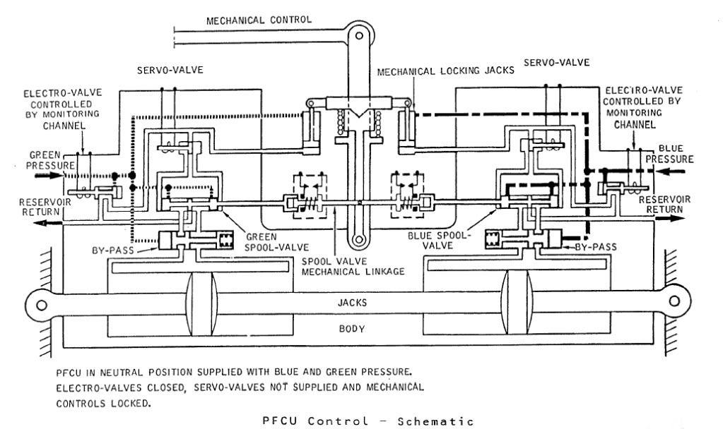
The diagram shows Green & Blue hydraulics supplied but the electro-valves (opened by the respective FBW channel) are both closed. You can see that the mechanical input lever is 'locked' to the PFCU input lever which will drive the SPOOL VALVE directly. When FBW is enabled, either the Blue or Green (never both together) ELECTRO-VALVE are signalled open, the ensuing hydraulic pressure then pushing the input clutch upwards and disengaging the mechanical input. FBW demands are now fed to the respective SERVO VALVE which will hydraulically send the SPOOL VALVE in the desired direction.
The Relay Jacks could be considered to be a little like a PFCU (you had 2 RJs per axix) but instead of the servo valves being driven by the FBW system they were driven by the autopilot and instead of driving a control surface, they drove the control runs. In manual flight the input spool was driven via a mechanical input lever, which would drive the RJ spool a little like Mech' signalling drove the PFCU spool. In A/P mode the mechanical input rod was de-clutched \xe0 la PFCU, but (and here's the clever part) this input was locked to the body of the Relay Jack which when it moved, drove the pilot's control in sympathy. (Control column, yoke or rudder pradals). As the respective control(s) was moved by the Relay Jack, the corresponding FBW position sensor (resolver) would change position and generate the FBW demand. (As the surface moved there was a feedback resolver at PFCU level).
As far as the FBW channels themselves went; there were 2 electronic signalling modes, Blue and Green, sub-divided into 3 groups (Inner Elevons, Outer & Mid Elevons and Rudders). Each group was independently monitored, and a fault in say the Rudder channel alone, would result in the rudders ONLY changing lanes. NOW ( ), The normal control channel was BLUE, and if this failed you would drop the respective channel into GREEN and if this failed you would drop into MECH. The selector switches (1 per group) enabled you to select BLUE/GREEN/MECH in that order. If for some reason you were selected to GREEN, a failure of that signalling lane would not drop you 'up' into BLUE, but into MECH. Your switch would only be in this position if you'd had a problem with BLUE, however you would select this on pushback while you were testing the flying controls, otherwise you spent your whole life selected to BLUE. As far as BA went, I can never remember a time personally when all 3 groups dropped from BLUE to MECH, but very rarely you might get a fault that caused a single group to briefly drop to MECH. Just about one of the very few common mode failures to each of the 3 groups would be a failure of the respective FBW static inverter. This thing, which was rightly monitored up to the hilt, produced a 26 Volt 1800 Hz output. (1800 Hz was chosen as this is not a harmonic of aircraft mainline 400 Hz AC supply)
Best regards
Dude
Hi again my friend. To further expand on CliveJ's superb explanation: Mechanical control inputs were fed to each of the 8 Powerd Flying Control Units (PFCUs), but in electronic signalling (either Blue or Green) these inputs were de-clutched at the PFCU input lever. When Fly By Wire' signalling is not available, the mechanical inputs (which as CliveL quite rightly points out) are driven by the Relay Jacks, now are locked to the input lever and can now move the input jack of the PFCU (known as the spool valve) and subsequently cause the PFCU to drive the control surface. (The body of the PFCU moved, the main jacks were attached at each end to structure and so obviously did not move). Hopefully this diagram will help visualising the process a little easier:
The diagram shows Green & Blue hydraulics supplied but the electro-valves (opened by the respective FBW channel) are both closed. You can see that the mechanical input lever is 'locked' to the PFCU input lever which will drive the SPOOL VALVE directly. When FBW is enabled, either the Blue or Green (never both together) ELECTRO-VALVE are signalled open, the ensuing hydraulic pressure then pushing the input clutch upwards and disengaging the mechanical input. FBW demands are now fed to the respective SERVO VALVE which will hydraulically send the SPOOL VALVE in the desired direction.
The Relay Jacks could be considered to be a little like a PFCU (you had 2 RJs per axix) but instead of the servo valves being driven by the FBW system they were driven by the autopilot and instead of driving a control surface, they drove the control runs. In manual flight the input spool was driven via a mechanical input lever, which would drive the RJ spool a little like Mech' signalling drove the PFCU spool. In A/P mode the mechanical input rod was de-clutched \xe0 la PFCU, but (and here's the clever part) this input was locked to the body of the Relay Jack which when it moved, drove the pilot's control in sympathy. (Control column, yoke or rudder pradals). As the respective control(s) was moved by the Relay Jack, the corresponding FBW position sensor (resolver) would change position and generate the FBW demand. (As the surface moved there was a feedback resolver at PFCU level).
As far as the FBW channels themselves went; there were 2 electronic signalling modes, Blue and Green, sub-divided into 3 groups (Inner Elevons, Outer & Mid Elevons and Rudders). Each group was independently monitored, and a fault in say the Rudder channel alone, would result in the rudders ONLY changing lanes. NOW ( ), The normal control channel was BLUE, and if this failed you would drop the respective channel into GREEN and if this failed you would drop into MECH. The selector switches (1 per group) enabled you to select BLUE/GREEN/MECH in that order. If for some reason you were selected to GREEN, a failure of that signalling lane would not drop you 'up' into BLUE, but into MECH. Your switch would only be in this position if you'd had a problem with BLUE, however you would select this on pushback while you were testing the flying controls, otherwise you spent your whole life selected to BLUE. As far as BA went, I can never remember a time personally when all 3 groups dropped from BLUE to MECH, but very rarely you might get a fault that caused a single group to briefly drop to MECH. Just about one of the very few common mode failures to each of the 3 groups would be a failure of the respective FBW static inverter. This thing, which was rightly monitored up to the hilt, produced a 26 Volt 1800 Hz output. (1800 Hz was chosen as this is not a harmonic of aircraft mainline 400 Hz AC supply)
Best regards
Dude
Last edited by M2dude; 16th Jan 2011 at 12:10 . Reason: Clarity; Oh for clarity
31st Jan 2011, 09:27
permalink Post: 1166
Landroger
Actually it was a great and moving experience Roger. All the people at the function were BA 'Concorde family', so the noise we made that evening was certainly sufficient. It sounds weird I know, but it was almost as if OAC was entering the spirit of the occasion. (And the aircraft was open for us to take photos, reminisce and quite honestly to help remind us all that something really wonderful was now missing from our lives). The aircraft is in such good general condition that she never really seems 'dead' at all
howiehowie93
Nothing missing here Howie. On the RIGHT HAND engines, ie. 2 & 4, Concorde had 2 hydraulic pumps, but on 1 & 3 engines there was only a single pump. What you can see is the spare gearbox provision for the extra YELLOW pump, right next to the IDG. (You can see the pipes coming from the GREEN hydraulic pump in the forward face of the gearbox, immediately forward of the 'blank').
Best regards
Dude
Quote:
| Oh and something that your photograph put in mind. It must be very seldom that even a parked aircraft is actually quiet. Being under AC like that must have been a bit un-nerving for someone so used to being next to Concorde, because she must be virtually silent? |
howiehowie93
Quote:
| is there something missing dead centre of the picture ?? to the Left of what I presume is a an FCU on the Gearbox? Looks to be a V-Band clamp still there hanging on the pad ?? |
Best regards
Dude
13th Mar 2011, 08:25
permalink Post: 1241
Quax .95
The trick was to get as many hydraulic systems online ASAP during engine start/pushback, and that's where the sequence was defined. Now my tired/worn out/time-expired brain recollects that number TWO engine was started first, this gave us GREEN and YELLOW systems, followed by number THREE engine, which now gave us BLUE system. Once these engines were successfully started the 2 air start trucks (oh for that darned APU) could be disconnected and preliminary system checks, including full and free flying controls, could be carried out. After push-back the outboard engines were started by using adjacent engine cross-bleed (as BRIT312 quite correctly stated years ago, there was no 'cross the ship' cross-bleed duct), the remaining system checks would be carried out. After this the tow-bar would be disconnected, the nose lowered to 5 \xb0 and our Concorde would taxi away ready to leap up into the heavens; the place that she truly belonged.
Best Regards
Dude