13th Aug 2010, 18:53
permalink Post: 4
Point taken GF, but it was discovered during development flying that that the Olympus 593 could be relit, given sufficient IAS, at almost any altitude within the normal flight envelope. The variable inlet would even be automatically scheduled, as a funcion of N1, in order to improve relight performance at lower Mach numbers. I certainly agree that you would decelerate and lose altitude fairly quickly under these conditions, however a multiple flame out was never experienced during the entire 34 years of Concorde flight testing and airline operation. There was, as a matter of interest an un-commanded deployment of a Concorde RAT AT MACH 2!! (The first indications of the event were when the cabin crew complained about 'a loud propeller sound under the rear cabin floor'. A quick scan of the F/E's panel revealed the truth of the matter). The aircraft landed at JFK without incident, and the RAT itself, apart from a very small leak on one of the hydraulic pumps, was more or less un-phased by the event. Although it sounds horrific, a prop rotating in a Mach 2 airstream, the IAS it 'felt' would be no more than 530 KTS at any time. The RAT was of course replaced before the aircraft flew back to LHR.
Not quite sure about your reference to the RAT on an F16 being Hydrazine powered; a Ram Air Turbine is just that, using the freely rotatting propellor to power hydraulics, electrics or both. Or do you mean the the F16 has an emergency power unit? Either way, it's fascinating stuff.
Yes, I do remember that the Germans used Hydrazine as a fuel during WW2: The father of one of our Concorde pilots was on an air raid to destroy one o the production plants there, this aviation business is such a small world.
13th Aug 2010, 22:14
permalink Post: 5
M2dude
Thanks for the reply, Concorde expertise is always interesting. I should not have called the F-16 Emergency Power Unit a RAT, it is indeed not. The Concorde RAT was located aft between the engine pods, correct?
What I found interesting is that the AC generators would remain on-line at all; they drop instantaneously at subsonic speeds and the associated N2 rpm. I believe the hydraulics on the 747 will power flight controls down to a pretty low IAS.
Four engine flameout is a very unlikely event, unless one runs into a volcanic cloud.
19th Aug 2010, 11:16
permalink Post: 25
Biggles78
Stupid, you? no way!! (Besides, I'm Mr Stupid of the aviation world, that's my title ). The thing is, out here in the world of flying machines, there are almost an infinite number of questions (and hopefully answers too). This applies to just about all aircraft from the Wright Flyer up!!.
Keep asking away, there are so many of us Concorde 'nuts' out here who are more than happy to help out/bore the socks off you.
Fuel burns: The problem was that when flying slow/taxying, Concorde was an extreme gas guzzler, even when idling each engine burnt around 1.1 tonnes/hour (so every 15 minutes after push back meant over a tonne gone). A typical taxi fuel would be around 1.4/1.5 tonnes, depending on the runway in use on the day. I'd have to leave it to some of my pilot/F/E friends to remember some of the specific fuel burns after take off etc, but I can at least give you some interesting consumption figures:
At the beginning of the take off roll, each engine would be burning around 21 tonnes/hour. (Made up of around 12 T/Hr dry fuel (Fe) and 9T/Hr afterburner (reheat to us Brits) fuel (Fr). As Fr was scheduled against Fe, as a function of inlet total temp (T1) by the time V2 was reached (around 220 KTS) the rising T1 has pushed the total fuel flow (Ft) up to a staggering 25 tonnes/hour/engine. As i've pointed out before in previous topics, although the afterburner only gave us a 17% improvement in take off thrust, it was responsible for around an 80% hike in fuel burn. (Hence that is whay it was only used sparingly). However when reheat was used for transonic acceleration, it used a dramatically reduced schedule (roughly a 60% rise in fuel flow) , so it was not quite as scary. The afterburner would be lit at the commencement of the acceleration (0.96 Mach) and cancelled completely at 1.7 Mach. After this time the aircraft would accelerate on dry power only up to mach 2 and beyond. (The cooler the temperature the quicker the time to Mach 2). On an ISA+ day, it sometimes felt that the aircraft was flying through cold porridge, and could take quite a while to get to Mach 2 after reaheat cancellation, where as on a nice ISA - day, she would go like a bat out of hell, and the AFCS would have to jump in to prevent overspeeds.
Before I hit some more numbers, let me say that with Concorde, TOC = TOD!! After reheat cancellation at Mach 1.7, the aircraft would be at FL 430. The aircraft would climb at an IAS of 530 KTS until Mach 2 was reached at fractionally over FL500. From then on the aircraft would cruise/climb as fuel was burnt, up to a maximum of FL600. On warmish days (eg. the North Atlantic) TOD would typically be around FL570-580. On a cool day (the lowes temperatures would of course be reached in the more tropical regions; the LGR-BGI sector encountered this), FL 600 would be reached easily and she would love to climb some more. BUT, the aircaft was only certificated to 60,000' with passengers onboard, for decompression emergency descent time reasons, and so we were stuck with it. The pity is of course, the fuel burn would have been improved, but we never were able to take advantage of this. On test flights however, the aircraft would routinely zoom climb to FL 630. On her maiden flight, aircaft 208 (G-BOAB) reached an altitude of 65000'; the highest recorded Concorde altitude was on one of the French development aircraft, which achieved 68,000'. On a technical point, the analog ADC's were 'only' calibrated to 65,000'.
Anyway, back to some figues; at Mach 2, 50,000', the typical fuel burn per engine would be around 5 tonnes/hour, falling to around 4.2 tonnes/hour at 60,000'.
THE NOSE You are quite correct in your assumption, there were two positions of droop: 5 deg's for taxi/take-off and low speed flight and 12.5 deg's for landing. The glazed visor retracted into the nose and could ONLY be raised once the nose was fully up, and had to be stowed before the nose could move down. There were 2 emergency nose lowering sysyems; one using stby (Yellow) hydraulics and a free-fall system. Free-fall would drop the nose all the way to 12.5 deg's, the visor free falling into the nose also.
Stupid, you? no way!! (Besides, I'm Mr Stupid of the aviation world, that's my title
). The thing is, out here in the world of flying machines, there are almost an infinite number of questions (and hopefully answers too). This applies to just about all aircraft from the Wright Flyer up!!.
Keep asking away, there are so many of us Concorde 'nuts' out here who are more than happy to help out/bore the socks off you.
Fuel burns: The problem was that when flying slow/taxying, Concorde was an extreme gas guzzler, even when idling each engine burnt around 1.1 tonnes/hour (so every 15 minutes after push back meant over a tonne gone). A typical taxi fuel would be around 1.4/1.5 tonnes, depending on the runway in use on the day. I'd have to leave it to some of my pilot/F/E friends to remember some of the specific fuel burns after take off etc, but I can at least give you some interesting consumption figures:
At the beginning of the take off roll, each engine would be burning around 21 tonnes/hour. (Made up of around 12 T/Hr dry fuel (Fe) and 9T/Hr afterburner (reheat to us Brits) fuel (Fr). As Fr was scheduled against Fe, as a function of inlet total temp (T1) by the time V2 was reached (around 220 KTS) the rising T1 has pushed the total fuel flow (Ft) up to a staggering 25 tonnes/hour/engine. As i've pointed out before in previous topics, although the afterburner only gave us a 17% improvement in take off thrust, it was responsible for around an 80% hike in fuel burn. (Hence that is whay it was only used sparingly). However when reheat was used for transonic acceleration, it used a dramatically reduced schedule (roughly a 60% rise in fuel flow) , so it was not quite as scary. The afterburner would be lit at the commencement of the acceleration (0.96 Mach) and cancelled completely at 1.7 Mach. After this time the aircraft would accelerate on dry power only up to mach 2 and beyond. (The cooler the temperature the quicker the time to Mach 2). On an ISA+ day, it sometimes felt that the aircraft was flying through cold porridge, and could take quite a while to get to Mach 2 after reaheat cancellation, where as on a nice ISA - day, she would go like a bat out of hell, and the AFCS would have to jump in to prevent overspeeds.
Before I hit some more numbers, let me say that with Concorde, TOC = TOD!! After reheat cancellation at Mach 1.7, the aircraft would be at FL 430. The aircraft would climb at an IAS of 530 KTS until Mach 2 was reached at fractionally over FL500. From then on the aircraft would cruise/climb as fuel was burnt, up to a maximum of FL600. On warmish days (eg. the North Atlantic) TOD would typically be around FL570-580. On a cool day (the lowes temperatures would of course be reached in the more tropical regions; the LGR-BGI sector encountered this), FL 600 would be reached easily and she would love to climb some more. BUT, the aircaft was only certificated to 60,000' with passengers onboard, for decompression emergency descent time reasons, and so we were stuck with it. The pity is of course, the fuel burn would have been improved, but we never were able to take advantage of this. On test flights however, the aircraft would routinely zoom climb to FL 630. On her maiden flight, aircaft 208 (G-BOAB) reached an altitude of 65000'; the highest recorded Concorde altitude was on one of the French development aircraft, which achieved 68,000'. On a technical point, the analog ADC's were 'only' calibrated to 65,000'.
Anyway, back to some figues; at Mach 2, 50,000', the typical fuel burn per engine would be around 5 tonnes/hour, falling to around 4.2 tonnes/hour at 60,000'.
THE NOSE You are quite correct in your assumption, there were two positions of droop: 5 deg's for taxi/take-off and low speed flight and 12.5 deg's for landing. The glazed visor retracted into the nose and could ONLY be raised once the nose was fully up, and had to be stowed before the nose could move down. There were 2 emergency nose lowering sysyems; one using stby (Yellow) hydraulics and a free-fall system. Free-fall would drop the nose all the way to 12.5 deg's, the visor free falling into the nose also.
Last edited by M2dude; 19th Aug 2010 at 12:40 . Reason: mistooks
22nd Aug 2010, 03:45
permalink Post: 60
Nick Thomas
... My other query concerns the FE. I understand that he set take off power etc...
Actually the F/E didn’t set T/O power, but did set most of the other power settings.
Broadly speaking, taxy-out to gear up, and gear down to engine shut down, the handling pilot operated the throttles. At other times, it was (almost) always the F/E.
Bear in mind that several of the routine engine power changes were effected through controls other than the throttles. For instance, selection of the re-heats, engine control schedules, engine ratings and intake lanes were all switch selections.
... I also understand that he also checked the pilots inputs into the INS system...
Correct, using INS3.
...So was he/she also a qualified pilot?..
No, they were professional flight engineers, who held a Flight Engineers Licence; they were not pilots biding their time before moving to the right hand seat.
I believe one or two may have held a PPL, but that was purely incidental, not a requirement.
All of the Concorde FEs had spent years on the VC10, B707, DC10, L10-11 or B747 fleets before coming to Concorde.
Biggles78
...Am I right or even slightly so in thinking that cruise climb and cruise descent was the flight...
Cruise climb, yes. Cruise descent, no.
...and there was minimal actual level cruise in the "pond" crossing?..
Correct, any level flight in the “cruise”, was just coincidence, probably caused by the outside air temperature increasing very gradually. Typically, she drifted up at around 30 to 50 fpm, but, if encountering warmer air, she would start to drift back down, in order to maintain M2.0.
... As you have said, fuel flow was reduced the higher you got. I think it was 5T per powerplant at FL500 down to 4.1T at FL600...
Rather optimistic figures for FL500 I’d have said! 6,000kg/hr/engine would have been nearer the mark!
...I am curious to see how much less fuel would have been used at the higher FLs considering it was reduced by 900Kg/hr for just 10K feet...
The reason the fuel flows dropped so much at the higher altitudes was that the aircraft had to be a lot lighter before she would get up there. It was her lighter weight that was the primary reason for the reduced fuel flows, not the higher altitude.
Forgive me if I’ve misunderstood you, but in her cruise climb, Concorde was flown at her optimum speed (M2.00) with (constant) optimum power set (max cruise power) and so (assuming a constant OAT above the tropopause) the only thing which affected her cruising altitude was her weight.
So, in theory at least, in cruise climb, she was always at her optimum altitude.
Any variation from that optimum altitude, such as a premature climb to higher altitudes, would have cost fuel, not saved it.
... How much of the descent was carried out while supersonic...
At the decel point, the cruise climb ceased and she was flown level at constant altitude. The F/E partially throttled back the engines and she stayed in level flight until her speed reduced to 350kts IAS, typically M1.5.
This took about 50nm, and most of the passengers would have sworn that they were already descending.
She then descended at 350kts IAS, meaning the Mach number would reduce constantly. On a straight in approach to JFK, with no subsonic cruise section, she would become subsonic descending through (around) FL350.
For a straight in approach, in zero wind, on a standard day, from FL600 to touchdown, typical figures would be something like a track distance of around 200nm, flying time of 22 minutes and 3,500kg of fuel.
Into LHR, she had to be subsonic much further away from her destination, and then had a subsonic cruise section on airways, so a slightly different procedure was used, and approaching FL410 she was slowed still further, becoming subsonic around FL400.
Anonymous
In response to your PM, earlier posters were correct in what they posted, however the manual reversion they refer to is a reversion from electrical to mechanical signalling to the flying controls.
There was no way to operate the flying controls manually in the absence of hydraulic power.
22nd Aug 2010, 09:09
permalink Post: 62
I feel like the fog is begining to clear and I am getting a slight understanding of how she flew. I was hung up with her flying at Mach speeds where as she was flown at an IAS (specific the the profile she was in). The Mach speed, especially when high, was a result of the temperature and not because she was f a s t ! The altitude flown was due to temperature and weight of the areoplane. This is true of all aeroplanes but due to the extreme environment this was more true of Concorde?
The subsonics have issues with Coffin Corner (I think I read that one Airbus model had somehting like 7kts between the high and low end of the envelope when up high); did Concorde have this "problem"?
I remember reading the BA Concorde flew with 2 Captain Pilots (and of course the most important Flight Engineer) and when I was watching The Rise and Fall of the Concorde , I was looking for the 4 bars in the RHS. Didn't see one but on the Air France Concorde the RHS pilot had 3 stripes. Was this correct or are my "little grey cells" confused?(sorry can't type a Belgium accent )
)
I don't know why this popped into my head but what was her glide ratio if all the engines stopped? Maybe because I remember from my early training being told the a B707 had a better glide ratio than the PA28-140 I was learning in. Now that was an eye opener at the time.
The subsonics have issues with Coffin Corner (I think I read that one Airbus model had somehting like 7kts between the high and low end of the envelope when up high); did Concorde have this "problem"?
I remember reading the BA Concorde flew with 2 Captain Pilots (and of course the most important Flight Engineer) and when I was watching The Rise and Fall of the Concorde , I was looking for the 4 bars in the RHS. Didn't see one but on the Air France Concorde the RHS pilot had 3 stripes. Was this correct or are my "little grey cells" confused?(sorry can't type a Belgium accent
)
I don't know why this popped into my head but what was her glide ratio if all the engines stopped? Maybe because I remember from my early training being told the a B707 had a better glide ratio than the PA28-140 I was learning in. Now that was an eye opener at the time.
22nd Aug 2010, 12:29
permalink Post: 65
 Galaxy Flyer
Quote:
| One more question, could the Concorde lose pressurization, descend to some low level (FL180 or below, perhaps FL100) and make it to scheduled destination or would a divert to Shannon or Gander be required? What was a low level cruise speed? |
It's great that Bellerophon is posting here again; we need a steely eyed Concorde pilot's input here (not just the boffins/nutters and nerds [that's me
 ]. To touch more on a couple of his valid points;
Fuel burn: The aircraft would naturally require less fuel as she became lighter and as a consequence gently climbed to maintain cruise Mach number, this is what the engine control system was doing all the time, even though the throttles were wide open it was 'tweaking'.. BUT, the decreasing IAS as you climbed, due of course to the reducing density, just like any other aircraft meant that drag was reducing too, so it was a combination of both of these factors, reducing weight and reducing drag.
Flying controls: It was a slightly weird but wonderful arrangement; pilots inputs would move a servo valve in the hydraulic relay jack, the jack would move in response and drive both a resolver AND mechanical linkages. The resolver ourput was sumed with the flying control position resolvers, and the error signal was fed into an autostab' computer, where it was summed with stabilisation demands (primarily axis rate and acceleration). The autostab computer would the directly drive the surface, and the reducing error signal would reduce the demand etc. While all this was going on, the mechanical linkages would slavishly follow, but as long as you were in FBW (what we used to call 'signalling') mode, these mechanical inputs were de-clutched at the PFCU, so did nothing at all. Only if there was an EXTREMELY unlikely failure of BOTH FBW channels would these inputs be clutched in and the flying control group (rudders, inner elevons or outer and mid' elevons) would then be in Mechanical signalling. The system redundancy was checked after engine start on every flight. But to reinforce what Bellerophon stated, there was no mechanical reversion here; without hydraulics you had nothing. Another aside here; the designers, being paranoid like all good designers (no offence Christiaan
 ) were worried what would happen if the controls would somehow jam up. A jammed mechanical flying control input run itself would have no effect on FBW operation whatsoever, due to spring boxes being fitted to the runs. A 'Mech Jam' light would be set, together with a separate red light and audio warning, but this was all. But to completely protect against the aircraft was fitted with a Safety Flight Computer (SFC) system. The idea was, if a control axis (pitch or roll only) jammed up, the captain could press down on a switch light set between the two halves of his control wheel, (at the centre of the 'W') and the Emergency Flight Controls would activate. Strain gauges at the front of the control wheel, two sets on each control column for pitch and roll axis, would input into an SFC that would covert the control force into an elevon demand. These commands were then fed into the autostab' computers, and hence directly into the controls. (A little like L-1011 CWS in a way). There was a little test button that was used to test this system, again after engine start. So although the controls were jammed, the aircraft could still be flown. (Never used in anger I'm pleased to report).
But there was a problem; if this system was inadvertantly used, the results could have been catastrophic, as the system was extremely sensitive indeed, and full elevon movement could be enabled with only moderate effort. Because of this hairy prospect some safeguards were obviously put in place. The first safeguard was an interlock in the autostab' engage logic; If the switchlight had been inadvertently selected beforehand (the light was green by the way) you would not be able to engage pitch or roll autostab's (both channels too) so you would not be going flying until that was fixed. The second safeguard was a little more subtle; A plastic, frangible cover was fitted over the switchlight, unless the captain pressed reasonably hard the cover would prevent the switchlight from being pressed. At least that was the theory, in practice this little bit of plastic could be a pain in the ass
 . It was carefully fashioned, and I seem to remember BAe charging the airlines a few hundred pounds each for these things. If some wally fitted the cover upside down (and unless you were careful it was easy to do) THE THING WOULD NOT BREAK!! I remember at Fairford in 1976, G-BOAD was on pre-delivery flight testing, and the late great test pilot John Cochrane was doing a test of the system. The cover on this occasion HAD been fitted upside down, and of course he could not plunge his thumb through it and engage the EFC button. After trying everything, in the end he removed a shoe, took out his pen, and smashed the plastic cover until it broke. (It's OK, the autopilot was engaged at the time). Unfortunately, his combined shoe/pen emergency device also wrecked the switchlight as well, so the system still could not engage. (There was only a switchlight on the captain's side). After he landed and he confronted us all with his dilemma, he was shaking; not with rage but with laughter. (This was the great John Cochrane, sometimes the dour Scotsman but he was always able to see the lighter side). After that event, careful instructions were issued regarding the fit of the cover, and it was modified and made a little more frangible.
Last edited by M2dude; 23rd Aug 2010 at 00:02 . Reason: will engineers ever learn to spell?
22nd Aug 2010, 13:18
permalink Post: 66
Biggles78
...The altitude flown was due to temperature and weight of the areoplane. This is true of all aeroplanes...
Sadly, it isn’t, as subsonic aircraft are allocated a specific cruising flight level and often - for example on the North Atlantic Track system - a specific cruising Mach number as well, and no deviation from that clearance is permitted without specific permission from ATC. Obviously everyone flight plans at the most economic heights and speeds for their aircraft type, but in busy airspace not everyone gets what they want!
Think of your flight plan as being Angelina Jolie, and your ATC clearance as being your wife. Your flight plan is what you’d really like to have, but your ATC clearance is what you’re going to have to live with!
... altitude flown was due to temperature and weight of the areoplane...this was more true of Concorde?...
Subsonic aircraft could equally benefit from using cruise-climb techniques (early long range aircraft crews knew all about cruise-climb techniques and used them when able) but with the large number of subsonic aircraft now using the world’s airways it is impractical for ATC to allow them to drift up and down at will, and so they are assigned specific cruising altitudes.
Few other aircraft got up to Concorde’s cruising levels, and so ATC were able to issue much more flexible clearances to her.
A typical Concorde ATC clearance would have allowed her to accelerate to M2.00 whilst operating within a "block" of altitude, rather than at a specific flight level. Typically this block clearance would have been to operate anywhere between FL450 up to FL600 without restriction.
So, unlike subsonic aircraft assigned a fixed cruising altitude such as FL350, Concorde could, and did, drift up or down, and was thus able to remain at the optimum altitude for the prevailing conditions throughout most of the flight.
... I remember reading the BA Concorde flew with 2 Captain Pilots (and of course the most important Flight Engineer)...
Concorde operated, as did all 3 crew aircraft in BA, with a standard crew of a Captain, F/O and F/E.
A small number of trips had two Captains on board (or two F/Es for that matter) when training or checking was going on, or an extra crew member was carried for PR purposes, but otherwise, the vast majority of occasions, just the standard crew was on board. Everyone preferred it that way, especially the F/O and F/E!
... The subsonics have issues with Coffin Corner (I think I read that one Airbus model had somehting like 7kts between the high and low end of the envelope when up high); did Concorde have this "problem"?...
Have a look at this picture of G-BOAE, cruising at her maximum certificated altitude of FL600, en-route to Barbados on 16 August 2003:
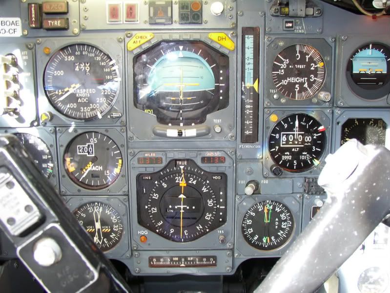
The available IAS speed range is shown on the ASI, and lies between the yellow and black Barbers Pole, currently indicating 440kts, and the white bug set to 300kts, the VLA ( L owest A uthorised speed) at this altitude.
The available Mach speed range is shown on the Mach meter, and lies between the yellow and black Barbers Pole, currently indicating M2.05, and the yellow bug which indicates the lowest Mach number allowed for the current aircraft CG position (the AFT limit) currently showing M1.35.
So, given that at her maximum altitude she had a speed range of 140kts IAS and a Mach range of M0.7, we can see that coffin corner was not a problem!
main_dog
...I too would like to ask what her idle thrust glide ratio was...
By my calculations, the figures quoted for a straight in approach, give an average glide ratio of around 20:1, however these were for a standard decel/descent, and on Concorde the early part of the decel/descent was not flown at idle power.
A considerable amount of power was left on initially, around 94% N2, for various reasons, and only below M1.0 were the throttles usually selected to idle.
I hadn’t noticed it until now but there does not appear to have been a chart giving glide distance at idle thrust!
However, since the speeds to be flown during the “4 Eng Flame Out” procedure were not too far from the normal decel/descent speeds, I’ll hazard a guess (and that is all it is) that the glide distance from FL600, with no thrust, would have been about 150nm, giving a glide ratio of around 15:1.
...The altitude flown was due to temperature and weight of the areoplane. This is true of all aeroplanes...
Sadly, it isn’t, as subsonic aircraft are allocated a specific cruising flight level and often - for example on the North Atlantic Track system - a specific cruising Mach number as well, and no deviation from that clearance is permitted without specific permission from ATC. Obviously everyone flight plans at the most economic heights and speeds for their aircraft type, but in busy airspace not everyone gets what they want!
Think of your flight plan as being Angelina Jolie, and your ATC clearance as being your wife. Your flight plan is what you’d really like to have, but your ATC clearance is what you’re going to have to live with!
... altitude flown was due to temperature and weight of the areoplane...this was more true of Concorde?...
Subsonic aircraft could equally benefit from using cruise-climb techniques (early long range aircraft crews knew all about cruise-climb techniques and used them when able) but with the large number of subsonic aircraft now using the world’s airways it is impractical for ATC to allow them to drift up and down at will, and so they are assigned specific cruising altitudes.
Few other aircraft got up to Concorde’s cruising levels, and so ATC were able to issue much more flexible clearances to her.
A typical Concorde ATC clearance would have allowed her to accelerate to M2.00 whilst operating within a "block" of altitude, rather than at a specific flight level. Typically this block clearance would have been to operate anywhere between FL450 up to FL600 without restriction.
So, unlike subsonic aircraft assigned a fixed cruising altitude such as FL350, Concorde could, and did, drift up or down, and was thus able to remain at the optimum altitude for the prevailing conditions throughout most of the flight.
... I remember reading the BA Concorde flew with 2 Captain Pilots (and of course the most important Flight Engineer)...
Concorde operated, as did all 3 crew aircraft in BA, with a standard crew of a Captain, F/O and F/E.
A small number of trips had two Captains on board (or two F/Es for that matter) when training or checking was going on, or an extra crew member was carried for PR purposes, but otherwise, the vast majority of occasions, just the standard crew was on board. Everyone preferred it that way, especially the F/O and F/E!
... The subsonics have issues with Coffin Corner (I think I read that one Airbus model had somehting like 7kts between the high and low end of the envelope when up high); did Concorde have this "problem"?...
Have a look at this picture of G-BOAE, cruising at her maximum certificated altitude of FL600, en-route to Barbados on 16 August 2003:
The available IAS speed range is shown on the ASI, and lies between the yellow and black Barbers Pole, currently indicating 440kts, and the white bug set to 300kts, the VLA ( L owest A uthorised speed) at this altitude.
The available Mach speed range is shown on the Mach meter, and lies between the yellow and black Barbers Pole, currently indicating M2.05, and the yellow bug which indicates the lowest Mach number allowed for the current aircraft CG position (the AFT limit) currently showing M1.35.
So, given that at her maximum altitude she had a speed range of 140kts IAS and a Mach range of M0.7, we can see that coffin corner was not a problem!
main_dog
...I too would like to ask what her idle thrust glide ratio was...
By my calculations, the figures quoted for a straight in approach, give an average glide ratio of around 20:1, however these were for a standard decel/descent, and on Concorde the early part of the decel/descent was not flown at idle power.
A considerable amount of power was left on initially, around 94% N2, for various reasons, and only below M1.0 were the throttles usually selected to idle.
I hadn’t noticed it until now but there does not appear to have been a chart giving glide distance at idle thrust!
However, since the speeds to be flown during the “4 Eng Flame Out” procedure were not too far from the normal decel/descent speeds, I’ll hazard a guess (and that is all it is) that the glide distance from FL600, with no thrust, would have been about 150nm, giving a glide ratio of around 15:1.
23rd Aug 2010, 14:03
permalink Post: 81
On the ITVV Concorde DVD the Captain explains that during the cruise climb at mach 2 the auto throttles were armed and would be used as required. Then during descent the throttles were gradually pulled back whilst the autopilot was given an IAS of I think 350 knots. Therefore the plane would have to descend to maintain that speed. He explained that the power settings were chosen to ensure that there was sufficent cooling etc.
My query is if an autoland was to be undertaken was the auto throttle system able to maintain the required landing speed or would the pilot have to manage the throttles? I guess that decreasing or increasing the pitch to control speed when on the glide slope would not be a good idea.
Thanks again
Nick
23rd Aug 2010, 14:16
permalink Post: 82
Approach handling was an interesting exercise - being so far down the back of the drag curve (over 100kts below best L/D) very accurate thrust handling was required.
The autothrottle was always used for approach if servicable, except for a two-engined approach, and was absolutely excellent. There were two, operating in parallel, and if the speed was more than a couple of knots out for more than a few seconds it was unusual. In IAS ACQ mode there was an active input from the INS which tracked grounspeed and so enabled anticipatory throttle movements during wind changes - if an autoland runway was available the preferred method of dealing with an approach likely to experience windshear was to carry out an autoland. (I think I speak for everyone, though, if I express a preference for the just going somewhere else option).
In Supercruise one autothrottle only was rearmed if the associated autopilot was engaged - it wasn't active but was available to cater for sudden drops in temperature which could cause unpleasant sudden high rates of climb if the temp shear was sufficient.
The rest of the flight - basically manual thrust, usually with the throttles fully forward.
Maybe one day we'll start making aeroplanes with such sophisticated systems again...........there's still lots that hasn't been hinted at on this thread
23rd Aug 2010, 18:49
permalink Post: 85
yoke feedback
Biggles:
Yep, there was feedback. In this respect, the implementation of FBW had a rather different philosophy to FBW Airbus'.
Below 200kts it was basically a spring feedback, above that speed it was achieved throught the feel system, not entirely unlike conventional aircraft.
Of course, the feel was tempered also by the autostab system, which didn't feedback through the yoke, but did make control surface inputs. A basic analogy is to imagine a yaw damper, but on all three axes. (It was of course rather more sophisticated, especially in pitch).
During airtests we would fly portions of the supersonic accel without autostabs and it was then very obvious exactly how much input was being made - great care was needed to remain within sensible bank angles in the low supersonic regime.
Also - watch a video of the control surfaces in the latter stages of the approach and landing - all those rapid deflections are the autostabs overlaid on the pilot's inputs. One has to remember that the aircraft is effectively statically unstable in pitch at approach speeds, so a pilot up-elevator input would soon be followed by a countering autostab elevon-down to contain the tendency to keep pitching up, and vice-versa. Gusts affecting the IAS would also create an input.
All of which means the basic spring feel below 200kts is not as basic as it sounds.....and in normal signalling modes (ie FBW and autostab active) the amazing thing is that the aircraft handled beautifully through an 1100kt speed range.
If you look at a picture of the flightdeck you will see a row of 14 white switches full width of the fwd edge of the overhead panel. These were autostab pitch/roll/yaw, feel pitch/roll/yaw left and right systems and the two pitch trim switches (which played a big part in the low-speed protection).
If any of them dropped out you could be sure that the first thing the nearest pilot would do would be to try to re-engage them, as it made for a vastly more pleasant life.
24th Aug 2010, 22:49
permalink Post: 101
ChristiaanJ
aaah yes, Max Climb/Max Cruise modes. I'd not forgotten this my friend, I was going to say a few words about that in a future post, but maybe we can do that now. (And I'd love to hear more of your comments on this here too, ChristiaanJ). The intake and autopilot modifications were in a way complimentary it's true, but really dealt with separate problems, at least in my view:
The intake control unit software change (a change to the control law that limited engine N1 as a function of intake local Mach number, Mo, and inlet total temperature, T1) was able to put an absolute limit on aircraft achievable Mach number during Mmo overshoots, but it would not PREVENT Mmo overshoots occurring altogether, it was more of a safety brake. This particular overspeed problem manifested itself well before route proving, and in fact the intake system 'fix' resulted in the Thrust Auto Reduce System being deleted, electronic control boxes and all. The TAR system was fitted on all development aircraft equiped with the digital intake system, and it tried (in vain) to limit extreme Mach overshoots. The production aircraft retained the TAR wiring and locked out circuit breakers, as well as two vacant spaces on the electronic racks. The prime reason for all these efforts were that some of the rapid excessive Mach overshoots quite often drove the intake into surge; the modification to this N1 limiter control enabled engine mass flow to be controlled in such a way that these surges could be prevented during temperature shears. The aircraft Mach limit was an extremely useful fringe benefit.
The AFCS mode change from what was Max Op and Max Op Soft (always loved that name) to Max Climb/Max Cruise was at a stroke able to deal with the regular Mmo overspeeds that kept on occuring during, as you say, the route proving trials of 1975, when British aircraft G-BOAC and the French aircrfraft F-BTSD carried out pre entry into service evaluation flights, SD sadly was the aircraft that was tragically lost at Gonez in July 2000). The Max Climb/Max Cruise AFCS mode combo is a mode like no other that I've personally seen before or since anywhere, (it for instance resulted an elsewhere taboo; an autopilot and an autothrotte working together IN A SPEED MODE).
This problem encountered primarily at lower lattitudes, (for example, G-BOAC doing route proving flights out of Singapore), occurring initially as the aircraft reached Mach 2. It was termed 'the insurmountable problem', but the AFCS designers (such as ChristiaanJ) fortunately did not have 'insurmountable problems' in their vocabulary. The issue was that the aircraft would have been climbing rapidly at Vmo of 530 KTS, with throttles at the gate as usual, At exactly 50,189' we hit what was known as 'the corner point' in the flight envelope, where 530 KTS IAS equated to Mach 2 exactly. Max Op mode would then 'let go' of the Vmo segment, and try and control the aircraft to Mach 2. (As the aircraft climbed, Vmo itself would progreesively decrease in order to equate to Mmo, or 2.04 Mach). But in very cold conditions, the aircraft still 'wanting' to accelerate, and the simple Max Op/Max Op Soft modes just could not cope with gentle pitch changes alone. The problem became even bigger during the cruise/climb when severe temperature shears occured, and routinely regular Mmo exceedences occured. Something had to be done, and something WAS done and how; enter Max Climb/Max Cruise. It was really a classic piece of design, where the aircraft would do the initial supersonic climb in Max Climb mode. This mode itself was relatively simple, in that it was more or less a Vmo -Vc hold mode. That meant that the difference at selection between indicated airspeed, Vc and Vmo would be maintained, with a vernier datum adjust to this being available. In practice this mode was selected pretty much at Vmo, so datum adjusting was not always required. Now comes the clever part; the autothrottle, this would operate in standy mode at this point, just waiting there doing nothing, with the throttles at maximum as before. So the aircraft would now climb as Vmo increased to 530 KTS, and then following a now constant Vmo of 530 KTS until the magic 'corner point' (51, 189' remember). Now all hell would break loose; the mode would automatically change to Max Cruise, the autothrottle would also be automaically selected to Mach Hold mode (initially datumed here to Mach 2) and the throttles would retard, attempting to hold this Mach 2 datum, and the autopilot is commands a 'fly up' signal, over a 20 second lag period to 600'/minute. Now comes an even cleverer (?) part; the autothrottle Mach Hold datum is gradually increased over a 100 second period towards Mach 2.02, and so in stable conditions the throttles would now gradually increase again until they once more reach the maximum limit. At this point, the autothrottles now come out of Mach Hold mode and back into the waiting in the wings standby mode. The autopilot would now cancel it's 600' fly up, demand, returning to a datum of Mach 2. There was a little more complexity built in also, where the difference between the 'commanded' and actual vertical speeds offset the autoplilot Mach 2 datum. This would apply whether the autothrottle had cut in (+600'/min demand) or with the throttles back at maximum (0'/minute demand. A positive climb error tweaked the cruise Mach up slightly, a negative error (eg. in a turn) the converse was true. The effect of all of this complexity was that the aircraft itself could 'scan' until it settled at a point where the throttles could be at maximum, and the speed between Mach 2 and 2.02. On the North Atlantic, with warmer ISA temperatures, there was usually just the initial routine with the autothrottle as you hit the corner point. However at lower lattitudes (eg. LHR BGI) there could be a few initial autothrottle intercepts before things settled down. This whole incredible routine completely took care of the insurmountable problem, a problem that was shown not only to be insurmountable, but was put to bed forever, by people like ChristiaanJ.
I hope that my explanation here does not sound too much like gibberish.
EXWOK
I think you've guessed right as far as my identity goes; it's great that it's not just Concorde pilots I can bore the socks off now
PS. I bet the ex-SEOs LOVED your comments
Dude
Last edited by M2dude; 25th Aug 2010 at 01:14 . Reason: missed out some info' (sorry)
5th Sep 2010, 02:29
permalink Post: 215
It was certificated - up to a point. Problematic? Maybe not, but it was a part of the flt envelope to be treated with respect.
Obviously there are no spoilers, and once you translate to 'vortex lift' (stalled in conventional terms) there is definitely no shortage of drag. (This happened at about 250kts at landing weight).
Supersonic - it was certainly no sailplane and an ability to increase drag wasn't required.
So - there is a bit of the flight envelope where you are subsonic, descending at about 350kts IAS, where you may need a bit of drag; e.g. to make the FL140 limit on the OCK 1A SID (as it then was) to LHR.
To facilitate this, engines 2 and 3 could be selected to reverse idle within certain strict limitations (most of which have now left my brain). The mechanism was to ask the SFE to arm the system on his panel and then to select reverse on the inboards. Where the system was slightly unreliable was that you were running the air-driven buckets with the engines at idle thrust - consequently they sometimes didn't make a full reverse selection, in which case you canx reverse on that engine and managed on one.
Clearly the big event would be if they didn't translate into fwd thrust, which is one of the reasons it wasn't done below 10 000'. I'm not aware of this happening.
To be honest it was only really used when ATC threw an alt constraint at you during the descent, because in general if you just pitched down to 380kts (Vmo when subsonic at typical approach weights) you would get the height off comfortably.
5th Sep 2010, 11:56
permalink Post: 217
Capt Chambo
Concorde was, as EXWOK says, could use reverse in flight, on the inboard engines only, and only as far as reverse idle, the mechanism of which was quite complex and did on occasion not do work as advertised. Bear in mind here that the Rolls Royce Olympus 593 was a pure turbojet with no bypass, and so a hot stream reverser only had to be used; the reverser buckets acting directly on the efflux as it did any reverser in the 'old' days. Also the same buckets that were used for reverse were also progressively opened up between Mach 0.55 and wide open at Mach 1.1, this giving a vital control enhancement to the divergencing efflux. The overall effect of this was to give a true overall convergent/divergent nozzle assembly, the ideal for any supersonic aircraft.
As far as inflight reverse goes, the amount of HP compressor delivery air (P3) required to actuate the bucket airmotor in flight at an idle thrust settings, was quite minimal to say the least, and some help was definitely needed here. The moment that inflight reverse was selected (on the inboard engines only remember) the OUTBOARD engines would have their idle N2 automatically increased, and some of THEIR P3 air supply was also automatically ported over (via an isolation valve) to the inboard buckets. This whole process was required in order to give a little added muscle to the bucket airmotors, and give the system a fighting chance. Even this however was still not quite enough, the inboard travelling buckets required minimal air loading on their surface, and so the primary nozzles for the affected engines (the primary nozzle lived just aft of the LP turbine, aft of the reheat assembly) was automatically signalled wide open in order to assist matters here, by reducing gas velocity. One the buckets had reached full reverse the primary nozzle was then signalled full close (this applied for normal ground reverse also) and the automatic increased idle on the outboard engines was cancelled. To enable the described process to occur, provided all four engines were at idle, a solenoid latched button on the F/E's station could be selected. This signalled a circuit that enabled the selection of idle reverse on the inboard engines only, the opening of the P3 isolation valve, the raising of the outboard engine's idle and maximum primary nozzle angle for the outboards as soon as reverse was then selected..
The whole system was just a little fragile here; failure of either the extra air supply, or the raised idle on the 'other' engine was usually enough to stop the process working correctly.
EXWOK
While flying 'up front' I only ever experienced the use of inflight reverse once. (The captain was a bit of an Animal, if you flying guys see what I mean ). I would not say that it felt as if we'd hit a brick wall, as I'd expected the sensation to feel, more like we were flying into the dumped contents of a very large manure truck
. The whole operation was so slick, we'd dumped the required amount of IAS more or less within a second or two, and normal thrust was immediately selected. As so often happened with you guys, you made it look too easy.
). I would not say that it felt as if we'd hit a brick wall, as I'd expected the sensation to feel, more like we were flying into the dumped contents of a very large manure truck
. The whole operation was so slick, we'd dumped the required amount of IAS more or less within a second or two, and normal thrust was immediately selected. As so often happened with you guys, you made it look too easy.
As far as the speed of the airmotor goes, I seem to remember that it was something in the order of 80,000 RPM at max chat; as you say faster (around twice as fast) as the standby horizon motor.
The basic core airmotor (not the whole assembly) was the same Garrett unit used on the P&W JT9 as well as the RB-211.
Dude
Concorde was, as EXWOK says, could use reverse in flight, on the inboard engines only, and only as far as reverse idle, the mechanism of which was quite complex and did on occasion not do work as advertised. Bear in mind here that the Rolls Royce Olympus 593 was a pure turbojet with no bypass, and so a hot stream reverser only had to be used; the reverser buckets acting directly on the efflux as it did any reverser in the 'old' days. Also the same buckets that were used for reverse were also progressively opened up between Mach 0.55 and wide open at Mach 1.1, this giving a vital control enhancement to the divergencing efflux. The overall effect of this was to give a true overall convergent/divergent nozzle assembly, the ideal for any supersonic aircraft.
As far as inflight reverse goes, the amount of HP compressor delivery air (P3) required to actuate the bucket airmotor in flight at an idle thrust settings, was quite minimal to say the least, and some help was definitely needed here. The moment that inflight reverse was selected (on the inboard engines only remember) the OUTBOARD engines would have their idle N2 automatically increased, and some of THEIR P3 air supply was also automatically ported over (via an isolation valve) to the inboard buckets. This whole process was required in order to give a little added muscle to the bucket airmotors, and give the system a fighting chance. Even this however was still not quite enough, the inboard travelling buckets required minimal air loading on their surface, and so the primary nozzles for the affected engines (the primary nozzle lived just aft of the LP turbine, aft of the reheat assembly) was automatically signalled wide open in order to assist matters here, by reducing gas velocity. One the buckets had reached full reverse the primary nozzle was then signalled full close (this applied for normal ground reverse also) and the automatic increased idle on the outboard engines was cancelled. To enable the described process to occur, provided all four engines were at idle, a solenoid latched button on the F/E's station could be selected. This signalled a circuit that enabled the selection of idle reverse on the inboard engines only, the opening of the P3 isolation valve, the raising of the outboard engine's idle and maximum primary nozzle angle for the outboards as soon as reverse was then selected..
The whole system was just a little fragile here; failure of either the extra air supply, or the raised idle on the 'other' engine was usually enough to stop the process working correctly.
EXWOK
While flying 'up front' I only ever experienced the use of inflight reverse once. (The captain was a bit of an Animal, if you flying guys see what I mean
). I would not say that it felt as if we'd hit a brick wall, as I'd expected the sensation to feel, more like we were flying into the dumped contents of a very large manure truck
. The whole operation was so slick, we'd dumped the required amount of IAS more or less within a second or two, and normal thrust was immediately selected. As so often happened with you guys, you made it look too easy.
As far as the speed of the airmotor goes, I seem to remember that it was something in the order of 80,000 RPM at max chat; as you say faster (around twice as fast) as the standby horizon motor.
The basic core airmotor (not the whole assembly) was the same Garrett unit used on the P&W JT9 as well as the RB-211.
Dude
Last edited by M2dude; 5th Sep 2010 at 13:25 .
5th Sep 2010, 18:51
permalink Post: 219
Hi
I have yet another question! Last year I watched a programme where James May went up in a U2. He explained that at FL700 the plane was flying in "coffin corner" and that the difference in IAS between the stall and the max speed was only 10 knots. I understand that it's due to the very low air pressure at such heights. As Concorde could fly up to FL600 I wondered what this safe airspeed window was during the cruise/climb phase of flight and if this window was framed by the air pressure and/or the CofG position?
Once again thanks to everyone for such great answers and also for the background information.
Regards
Nick
5th Sep 2010, 21:02
permalink Post: 220
Nick
,
Again I'll leave the full details to the real experts....
I saw that program with James May in the U2 too, so I know what you mean.
The "coffin corner" is the point for a subsonic aircraft where stall speed and limiting Mach number "meet" ; about 70000 ft for a U2, and considerably lower for an airliner. Either you stall, or you run into Mach buffet with control problems.
I'll try and find you a proper picture of the Concorde flight envelope (I have a few but one isn't scannable, the other is too ancient - preprod, yet another is 'buried' on a CD).
But nearly all of the edges and corners in that flight envelope "window" are a matter of certification.
You're not supposed to exceed M=2.04, Tt=127\xb0C, IAS= 530kts, simply because of the "wear and tear" on the aircraft.
You're not supposed to go above 60000ft because your passengers might no longer survive a window blow-out.
You're not supposed to go below 300kts above 41000ft, don't know if that's a minimum control speed or linked to the engines...
Yet Concorde has been flown to Mach=2.23 and 68000ft without ill efect....
So the basic limitations are not linked to the classic "coffin corner" at all.
CJ
6th Sep 2010, 09:17
permalink Post: 222
Coffin Corner
Nick Thomas
Just like Christiaanj I'm trying to dig up an accurate flight envelope diagram. (A lot of my Concorde 'technical library' is out on long term loan), but I would suggest that anywhere within Concorde's published flight envelope you never hit any equivilant to Coffin Corner, a la' U2. The whole issue is really one of air DENSITY, rather that pressure, where as you climb at a given Mach Number, your Indicated airspeed (IAS) falls away with altitude. (Velocity of sound being primarily tied to static air temperature). Now if you are climbing in the stratosphere, where temperature is more or less constant up to around 65,000', you can say that your TRUE Airspeed (TAS) is also constant with climb at a given Mach number. But lift and drag are functions of IAS (the equivalent airspeed that the aircraft would 'feel' at sea level) and not TAS. Because the U2 had a very low Maximum allowable Mach number (Mmo) as IAS fell away with altitude, it would get to the point where it's lowest permitted airspeed (we called this VLA) got to within a few knots of Mmo and severe aerodynamic buffering. i.e. you were screwed with nowhere to go but down
.
In the case of Concorde, Mach 2 at FL500 was 530KTS, falling to 430KTS at FL600. Although we have less lift due to 100KTS lower IAS, the aircraft is now much lighter (this is the whole principal of cruise/climb) which keeps the universe in balance, but drag is now significantly lower too, getting us better MPG
.
On the ASI, the only limitation displayed was Vmo; however the Machmeter did display fwd and aft CG limits at a given Mach number. The ONLY time that Concorde would experience relatively low speeds at altitude was at Top of Descent. I'm a little fuzzy here how it all worked exactly (it's an age thing you know), I'm sure one of the pilots can correct me, but I seem to remember that the autothrottle was disconnected, ALTITUDE HOLD was selected on the AFCS, and the throttles slowly retarded. (If you pulled back too far you'd often get a gentle 'pop surge' from the engines, and you had also to be wary of equipment cooling airflow too). The aircraft was then allowed to gently decelerate, still at TOD altitude, until Mach 1.6, when power was tweaked to give 350KTS IAS and IAS HOLD was selected. The aircraft was now free to carry out her loooong descent to 'normal' altitudes. VLA on Concorde was not directly displayed as you never flew anywhere near it, and also every pilot knew his VLA
. (Stray into this and you'd get a 'stick' shaker warning.
I hope this blurb helps Nick
Dude
6th Sep 2010, 12:52
permalink Post: 226
Although generally ignorant about aircraft, I have been absolutely rivetted by this thread, and can only sit in awe at the complexity and perfection that has been revealed here.
I've pretty much managed to keep up with the principals and technicalities involved, but there is one thing I don't understand. Could you explain to a complete novice the relationship between IAS, TAS ,GS and Mach no.?
Apologies if this is obvious to most here, but you can't get away with writing such a brilliant account of such a wonderful aircraft without attracting the odd ignorant byestander!
6th Sep 2010, 15:10
permalink Post: 229
Nice to see another Devon person here. I agree this is a great thread. Here is a simple explanation of airspeed.
A stationary aircraft, just like anything else is subject to static air pressure, which varies from place to place, day to day and decreases with an increase in altitude and.or a rise in temperature.
Once that aircraft starts moving through the air, it also experiences dynamic pressure which is the force of the air particles it meets as it moves. Of course the static pressure remains too, so the aircraft is experiencing static + dynamic which is called pitot pressure or total pressure. The laws of physics say that total pressure remains constant.
Indicated Airspeed (IAS) is a measurement of dynamic pressure which is described as 1/2 rho (rho is air density) X V2 (V= velocity). This is very important when talking about principles of flight (thrust, drag, stall speed etc)
Air density is a function of pressure and temperature, so if density (rho) is reduced V2 which is True Airspeed (TAS) has to have increased at a given IAS. (ie the same number of particles hit the aircraft in a given time)
In a nil wind situation TAS would be the same as your speed over the ground (GS). Groundspeed is then calculated by adding or subtracting wind speed from TAS. eg TAS 150kts, tail wind 20 kts = GS 170kts.
Fairly simple at low speeds. At speeds of 300kts and above the compressibility of air becomes an issue and has to be allowed for - the air is compressed as it stops against the aircraft. So TAS also includes an adjustment to compressibility.
Mach no is a percentage value of the speed of sound ie 0.85 = 85% speed of sound. Unfortunately the speed of sound changes with pressure but at sea level is around 760 mph and decreases as pressure decreases.
Aerodynamically things start going pear shaped as an aircraft nears the speed of sound as the airflow over parts of the aircraft can go supersonic. Aircraft approaching these kind of speeds have to fly mach numbers. Airliners typically fly Mach 0.80-0.85.
6th Sep 2010, 16:42
permalink Post: 231
Quote:
|
Originally Posted by
Shanewhite

Could you explain to a complete novice the relationship between IAS, TAS ,GS and Mach no.?
|
TAS (true air speed) is simple, it's the true speed of the aircraft through the air.
GS (ground speed) is equally simple, it's the speed of the aircraft over the ground i.e., TAS plus the component of the wind along the flight path. If your TAS is 1300 mph and you have a 100 mph tailwind, your GS will be 1400 mph.
Mach no. is TAS divided by the local speed of sound.
The speed of sound in air depends almost exclusively on the temperature: in a ' standard ' atmosphere it's 760 mph on the ground at +15\xb0C, drops to 660 mph at 37000ft / -57\xb0C and remains constant above that height.
It's IAS (indicated air speed) that's complicated....
Lift, drag, control forces, stability, etc. are all proportional to the 'dynamic pressure' that the aircraft experiences moving through the air.
This 'dynamic pressure' is proportional to density x TAS squared .
Now take an aircraft flying along horizontally at sea level, say at 200 mph.
Lift = weight, so the aircraft stays on a horizontal flight path.
Take this same plane, without changing anything else, to an altitude where the air density is half that at sea level.
Dynamic pressure is now half, so the lift is half as well, but the weight is still the same, so the aircraft can no longer fly horizontally.
So what do we do... we increase the TAS until the dynamic pressure is the same as it was at 200 mph at sea level.
Half the density, so (TAS squared) has to be double, so TAS has to be increased to 1.4 (sqrt of 2) x 200 mph = 280 mph.
This is somewhat confusing for the pilot.... He flies the same aircraft, same weight, same angle of attack, etc. but not the same TAS... he'd have to mentally juggle airspeed and density (altitude) the whole time to maintain horizontal flight at different levels.
It would be much easier if he had an indicator showing dynamic pressure... and maintain that constant for different altitudes.
This is where IAS comes in.
Stick your hand out of a car window. The force you feel is due to the dynamic pressure.
Stick a tube, closed at one end, into the airstream and measure the pressure with a basic pressure indicator, that's your dynamic pressure.
Now the 'clever' bit. Mark your indicator, not in bar or psi, but in mph, so that at sea level it will indicate the same speed as the TAS (200 mph in the example).
Now, same as above, go and fly at an altitude where the density is half, with a TAS of 280 mph. Your indicator will still show 200 mph, showing you that the dynamic pressure, hence the forces (lift, drag, etc.) are the same as those at sea level at 200 mph.
So the 200 mph is your IAS, your "indicated air speed".
It's the IAS that tells you what happens to your aircraft in terms of the forces and aerodynamics, and that's why figures such as the Vne (never-exceed speed) or the stall speed are always in mph or knots IAS , not TAS.
As a matter of fact, a pilot is not very much interested in TAS as such, and most aircraft do not even have a TAS indicator.
It's not until you start approaching the speed of sound that TAS becomes important, and even then it's not TAS as such that's used but its relation to the speed of sound, i.e., the Mach number.
OK, Shanewhite , it's a long and complicated description, but maybe it helps?
CJ
Edit PS : I see mykul10 already had a go as well. So much the better, explanations from two different sides nearly always complement each other!
6th Sep 2010, 22:18
permalink Post: 238
shanewhite
Following the excellent explanation given by ChristiaanJ about the relationships between OAT, Mach number, TAS and IAS (which I have now copied and shall shamelessly pass off as my own work in future
) if you wish to see how these relationships work in practice you might look back at the photo posted at reply #66.
You will see that at FL600 the aircraft had a GS of 1,139 kts whilst flying at M2.00 and an IAS of 429 kts.
We don\x92t know what the wind was, nor what the TAS or OAT were, but we can easily deduce that:
For obtaining Mach/TAS/Temp values quickly and easily, as well as other useful information on the atmosphere, this Standard Atmosphere Calculator website is extremely useful.
Best Regards
Bellerophon
Following the excellent explanation given by ChristiaanJ about the relationships between OAT, Mach number, TAS and IAS (which I have now copied and shall shamelessly pass off as my own work in future
) if you wish to see how these relationships work in practice you might look back at the photo posted at reply #66.
You will see that at FL600 the aircraft had a GS of 1,139 kts whilst flying at M2.00 and an IAS of 429 kts.
We don\x92t know what the wind was, nor what the TAS or OAT were, but we can easily deduce that:
- If the OAT was standard at FL600, at -56.5\xb0C, then, as at that temperature M2.00 equates to 1,147 kts TAS, in order to have a GS of 1,139 kts, she must have been flying into an 8 kt headwind.
- If the wind at that altitude was calm, then her GS of 1,139 kts must have been the same as her TAS. For M2.00 to be 1,139 kts TAS, then the temperature at FL600 must have been 3\xb0C colder than standard, at -59.5\xb0C.
- If , as was typical on a LHR-BGI sector, the OAT at FL600 was 10\xb0C colder than standard, at -66.5\xb0C, then M2.00 would equate to 1,120 kts TAS, so to have a GS of 1,139 kts, she must have been flying in a 19 kt tailwind.
For obtaining Mach/TAS/Temp values quickly and easily, as well as other useful information on the atmosphere, this Standard Atmosphere Calculator website is extremely useful.
Best Regards
Bellerophon