6th Sep 2010, 23:08
permalink Post: 240
Quick link to
Bellerophon
's post #66 and photo to save you having to 'leaf' back...
G-BOAE at Mach 2
Much as I look at that picture, I can't see the groundspeed.....
Ah, oh, ooooops!!!! Of course it's there, in the little window on the top right of the HSI (Horizontal Situation Indicator, the lower one of the two big central instruments).
Shanewhite , in a way, that illustrates that for flying the aircraft things like TAS and GS are not really that important... that's why there are no big instruments indicating TAS or GS, but only IAS and Mach, with only a little digital window for GS, which IS important for navigation (largely handled by the inertial navigation system, which is the system where the GS display comes from), but not for the minute-to-minute handling of the aircraft.
Bellerophon , dumb question from a techie... the 373 miles is presumably just the distance to the next INS waypoint?
CJ
G-BOAE at Mach 2
Quote:
|
Originally Posted by
Bellerophon
You will see that at FL600 the aircraft had a GS of 1,139 kts whilst flying at M2.00 and an IAS of 429 kts.
|
Ah, oh, ooooops!!!! Of course it's there, in the little window on the top right of the HSI (Horizontal Situation Indicator, the lower one of the two big central instruments).
Shanewhite , in a way, that illustrates that for flying the aircraft things like TAS and GS are not really that important... that's why there are no big instruments indicating TAS or GS, but only IAS and Mach, with only a little digital window for GS, which IS important for navigation (largely handled by the inertial navigation system, which is the system where the GS display comes from), but not for the minute-to-minute handling of the aircraft.
Bellerophon , dumb question from a techie... the 373 miles is presumably just the distance to the next INS waypoint?
CJ
7th Sep 2010, 07:12
permalink Post: 244
 Hi guys, here is a schedule showing CG against Mach number (It's very old just like the author here). I hope that it now completes our collection of flight envelope diagrams.
(
Bellerophon, by the way, your diagram is precisely the one that I was scouring around for). Great explanations by everybody on the Mach/TAS/IAS etc issue, mostly all clear and concise ( a couple of minor goofs that were subsequently corrected, otherwise very good) .
Hi guys, here is a schedule showing CG against Mach number (It's very old just like the author here). I hope that it now completes our collection of flight envelope diagrams.
(
Bellerophon, by the way, your diagram is precisely the one that I was scouring around for). Great explanations by everybody on the Mach/TAS/IAS etc issue, mostly all clear and concise ( a couple of minor goofs that were subsequently corrected, otherwise very good) .
If I were in the LEAST bit pedantic (and any here that know me would say that the b****d certainly IS
 pedantic), I would merely add that Concorde (like virtually all complex aircraft) relied on CALIBRATED airspeed (Vc) and not IAS, taking into acount plate and probe errors. Just as well I'm not pedantic
 .
.
Dude

Last edited by M2dude; 7th Oct 2010 at 18:12 .
19th Sep 2010, 20:06
permalink Post: 404
Quote:
|
Originally Posted by
EXWOK

Anecdotal rther than aerodynamic evidence here - but there was a noticable buffet as one decelerated, accompanied by a significant step in thrust requirement. That point was where we (flight crew) decided we were in vortex lift.Typical speeds would be 270-280 kts at TO mass and about 230-250kts at landing mass.
|
For some reason, those figures sound familiar even to me.... (from some other discussion, probably).
It would definitely put optimum subsonic cruise at about 350 kts in the "conventional lift" zone.
Quote:
| Anyone know some definite answers? |
CJ
19th Sep 2010, 20:09
permalink Post: 405
Yep - IAS. (or technically, CAS before I'm corrected!)
IIRC 400kts IAS was approximately best L/D at departure weights. (Low-level, obviously).
IIRC 400kts IAS was approximately best L/D at departure weights. (Low-level, obviously).
24th Sep 2010, 00:51
permalink Post: 459
Sorry - missed the second half of your question.
We didn't have any trouble flying procedures drawn at 185kts. If necessary you could fly and manoeuvre at 190kts IAS, it was just very thirsty and noisy like that. We wouldn't manage 10miles out at 210kts on a SID, but I didn't ever encounter a SID like that. In the case of terrain-constrained ops (which may cause the above) we would have to come up with some usable aternative.
The 'tightest' destination I recall was Sondrestrom (as it was still called then). Although noone in their right mind would land a heavy on RW28 (as it was) we had to demonstrate it in the sim. It really wasn't an issue in terms of turn radius, the trouble was the radalt ramping caused by terrain combined with our higher speed. It was just possible to avoid the dreaded GPWS.
Of course when you took the real thing there we just landed staright in on 10.
21st Nov 2010, 15:37
permalink Post: 751
Mr Vortex
An ejection was recommended because it was possible, not that was necessarily impossible to land a Draken dead stick. F-16s have done a number of them, I witnessed one at KTPA. There was a video of the HUD view of one at NAS Glenview, IL.
To your question, it would depend on distance to go to the airport, glide ratio (high but probably not terribly worse than any conventional airliner) and most importantly the capability of the RAT providing hydraulic power.
M2dude , any idea of the min IAS for the RAT to provide the juice and hydraulics? Would it be as low as Vapp minus some margin?
GF
21st Nov 2010, 21:37
permalink Post: 759
galaxy flyer
Well the RAT was 'advertised' to be able to maintain 4000 (ish) PSI on Green and Yellow systems down to around 200 KTS, so IN THEORY you'd be ok (ish), refering to Brit312's post. Incidently, one of the prime reasons that the engines were housed in twin nacelle pairs, rather than the original TU144 'monobloc' style was to eliminate the chance of a severe ripple surges flaming out all four engines. (But as the thing had half of the engine air passing over the massive stowed main undercarriage, they had other problems to worry about anyway).
I have to echo your point GF about carrying on asking questions, even if they may seem dumb at the time. It's all about how we all had to learn in the first place; Personally I'm happy to answer any questions at all here (the questions may not be stupid, but some of my answers........... ).
).
Regards to all
Dude
Quote:
| any idea of the min IAS for the RAT to provide the juice and hydraulics? Would it be as low as Vapp minus some margin? |
I have to echo your point GF about carrying on asking questions, even if they may seem dumb at the time. It's all about how we all had to learn in the first place; Personally I'm happy to answer any questions at all here (the questions may not be stupid, but some of my answers...........
).
Regards to all
Dude
30th Nov 2010, 10:16
permalink Post: 820
Hi DavvaP, and welcome. As far as ice on the wing goes, I'm sure as any of my pilot friends here will agree that she was treated just like a subsonic in that regard; any ice or snow build up on the surfaces of the wings would not be tolerated and would have to be removed before flight. (She may have had a revolutionary wing design, but still this was a wing nonetheless
 ). She would also require pre-flight chemical anti-icing/de-icing treatment from a ground truck just like the rest, in shall we say, 'less than tropical conditions'. (Winters in Prestwick during crew base training... such fond memories


 ). As far as active ice protection on the wings, there was a highly sophisticated Lucas electrical 'spraymat' system fitted, but only the wetted areas of the wing, forward of the engines were 'covered'. Two digitall cyclic timers (CTPUs) would automatically regulate cyclic switching on and off of 115 VAC for various load areas of the wing at a time at pilot pre-selectable intervals (2, 4 or 8 seconds). Also as part of this system, there was
continuous
de-icing for certain other load areas too, so you had a mix of cyclic and continuous de-icing in operation. The whole idea here was to prevent chunks of ice entering and damaging the engines, the only other areas of this electrical de-icing system were the intake lips and side-walls and also the D Box area above the auxilliary inlet vane, built into the spill door. (This would only operate if the auxilliary inlet door itself was open). The whole shooting match would automatically switch itself off, for obvious reasons, above a TAT of 15\xb0 C. (ie. the vast majority of the flight). The only other de-icing system (apart from the galley drain masts) was on the engine inlet guide vanes, but this was purely pneumatic and again would swith itself off above 15\xb0 C.
). As far as active ice protection on the wings, there was a highly sophisticated Lucas electrical 'spraymat' system fitted, but only the wetted areas of the wing, forward of the engines were 'covered'. Two digitall cyclic timers (CTPUs) would automatically regulate cyclic switching on and off of 115 VAC for various load areas of the wing at a time at pilot pre-selectable intervals (2, 4 or 8 seconds). Also as part of this system, there was
continuous
de-icing for certain other load areas too, so you had a mix of cyclic and continuous de-icing in operation. The whole idea here was to prevent chunks of ice entering and damaging the engines, the only other areas of this electrical de-icing system were the intake lips and side-walls and also the D Box area above the auxilliary inlet vane, built into the spill door. (This would only operate if the auxilliary inlet door itself was open). The whole shooting match would automatically switch itself off, for obvious reasons, above a TAT of 15\xb0 C. (ie. the vast majority of the flight). The only other de-icing system (apart from the galley drain masts) was on the engine inlet guide vanes, but this was purely pneumatic and again would swith itself off above 15\xb0 C.
I think you will find that precious little of Concorde is now not generally available in the public domain, some control software and laws are still I would expect covered by some sort of patent. (That is why when I publiished here the engine 'E Schedule' graphs I deliberately deleted the equations for the various running lines.
Your efficiency question was a valid one; as IAS and Mach number increase the aerodynamic drag (in all it's forms) will generally increase, but the efficiency OF A WELL DESIGNED powerplant wil also increase, and Concorde was definately no exception here. The real beauty of Concorde was just HOW MUCH the powerplant efficiency increased with increasing speed and more than totally eclipsed the aerodynamic drag rise with this increasing speed. At supersonic speeds, the closer you could fly to Vmo/Mmo the lower the fuel burn was. (Especiall true at Mach 2, although the autopilot would hold you Mach 2 (ish) in Max Cruise mode, flying closer to Mmo, Mach 2.04, would save fuel, assuming the static air temoerature was low enough to sustain this). This fact (along with about a million others) produced what we all like to call 'The Magic of Concorde'
Best Regards
Dude
). She would also require pre-flight chemical anti-icing/de-icing treatment from a ground truck just like the rest, in shall we say, 'less than tropical conditions'. (Winters in Prestwick during crew base training... such fond memories
). As far as active ice protection on the wings, there was a highly sophisticated Lucas electrical 'spraymat' system fitted, but only the wetted areas of the wing, forward of the engines were 'covered'. Two digitall cyclic timers (CTPUs) would automatically regulate cyclic switching on and off of 115 VAC for various load areas of the wing at a time at pilot pre-selectable intervals (2, 4 or 8 seconds). Also as part of this system, there was
continuous
de-icing for certain other load areas too, so you had a mix of cyclic and continuous de-icing in operation. The whole idea here was to prevent chunks of ice entering and damaging the engines, the only other areas of this electrical de-icing system were the intake lips and side-walls and also the D Box area above the auxilliary inlet vane, built into the spill door. (This would only operate if the auxilliary inlet door itself was open). The whole shooting match would automatically switch itself off, for obvious reasons, above a TAT of 15\xb0 C. (ie. the vast majority of the flight). The only other de-icing system (apart from the galley drain masts) was on the engine inlet guide vanes, but this was purely pneumatic and again would swith itself off above 15\xb0 C.
I think you will find that precious little of Concorde is now not generally available in the public domain, some control software and laws are still I would expect covered by some sort of patent. (That is why when I publiished here the engine 'E Schedule' graphs I deliberately deleted the equations for the various running lines.
Your efficiency question was a valid one; as IAS and Mach number increase the aerodynamic drag (in all it's forms) will generally increase, but the efficiency OF A WELL DESIGNED powerplant wil also increase, and Concorde was definately no exception here. The real beauty of Concorde was just HOW MUCH the powerplant efficiency increased with increasing speed and more than totally eclipsed the aerodynamic drag rise with this increasing speed. At supersonic speeds, the closer you could fly to Vmo/Mmo the lower the fuel burn was. (Especiall true at Mach 2, although the autopilot would hold you Mach 2 (ish) in Max Cruise mode, flying closer to Mmo, Mach 2.04, would save fuel, assuming the static air temoerature was low enough to sustain this). This fact (along with about a million others) produced what we all like to call 'The Magic of Concorde'
Best Regards
Dude
Last edited by M2dude; 30th Nov 2010 at 12:21 .
18th Dec 2010, 15:20
permalink Post: 876
JFK 31L, Kennedy 9 Departure, Canarsie transition, Concorde climb
Speedbird 2, cleared take-off 31L.
You call 3-2-1 Now , start your stopwatch, pre-set to countdown from 58 seconds, and slam the throttles fully forward till they hit the stops. Four RR Olympus engines start to spool up to full power and four reheats kick in, together producing 156,000 lbs of thrust, but at a total fuel flow of 27,000 US gallons per hour. A touch of left rudder initially to keep straight, as the #4 engine limiter is limiting the engine to 88% until 60 kts when it will release it to full power. The F/O calls Airspeed building, 100 kts, V 1 , and then, at 195 kts, Rotate . You smoothly rotate the aircraft, lift-off occurs at around 10\xb0 and 215 kts. You hear a call of V 2 but you keep rotating to 13.5\xb0 and then hold that attitude, letting the aircraft accelerate.
The F/O calls Positive Climb and you call for the Gear Up . On passing 20 feet radio height, and having checked the aircraft attitude, airspeed and rate of climb are all satisfactory, the F/O calls Turn and you slowly and smoothly roll on 25\xb0 left bank to commence the turn out over Jamaica bay. Some knowledgeable passengers will have requested window seats on the left side of the aircraft at check-in, and are now being rewarded with a very close look at the waters of Jamaica Bay going by very fast! As you accelerate through 240 kts, the F/O calls 240 and you pitch up to 19\xb0 to maintain 250 kts and keep the left turn going to pass East of CRI.
54 seconds from the start of the take off roll you hear the F/O counting down 3-2-1 Noise whereupon the F/E cancel the re-heats and simultaneously throttles back to noise abatement power, around 96% as you pitch the nose down to 12\xb0 to maintain 250 kts. It is less than a minute from start of roll and already 435 US gallons of fuel have been used.
Speedbird 2, contact departure, so long.
Turning through heading 235\xb0M, the F/E quickly re-applies full dry power as you pitch up to 17\xb0 to maintain 250 kts, but simultaneously reduce the left bank to 7.5\xb0, in order to increase both the radius of turn (to stay on the optimum noise abatement track) and the rate of climb (less bank, higher RoC).
On climbing through 2,500 ft you increase the bank angle back to 25\xb0 left bank and as you approach the 253\xb0 radial JFK, you hear 3-2-1 Noise from the F/O for the second time. The F/E actions the second noise-abatement power cut back, you pitch down to 12\xb0 and, if not in cloud, sneak a quick peek out of your left hand window, looking for the car park by the Marine Parkway bridge, as you would ideally like to pass right over the car park, if possible, as we tip-toe quietly across the Rockaway Beaches, in order to minimise the noise impact on the residents.
Keep the left turn going and intercept the 176\xb0 radial outbound from CRI, and at 5 miles DME from CRI, call for the F/E to slowly re-apply full climb power as you pitch up to maintain 250 kts. We are still in US territorial airspace, below 10,000 ft, and subject to statutory speed control.
Speedbird 2, present position direct to SHIPP, climb FL230, no speed control.
The F/O selects direct SHIPP in the INS and tells you that she has selected that information into your Flight Director. Having checked that the gear lever is at neutral, you call for the Nose Up , and then the Visor Up . Flight deck noise levels drop dramatically as the Visor locks up. Now more than 12 miles away from the coast, we are clear of US speed control requirements so lower the attitude to 9\xb0, accelerate to V MO , currently 400 kts, and ask for the After Take Off Checks.
Speedbird 2, present position direct to LINND, climb in the block FL550-600, accelerate Mach 2.0
Call for the Climb Checklist at Mach 0.7, which will trigger the F/E to start pumping fuel rearwards to move the CG aft, then when he's done that, straight into the Transonic Checklist . Maintain 400 kts IAS, and around 24,500 ft, at M0.93, ask for the re-heats back on, in pairs, and raise the nose by 3\xb0 to maintain 400 kts as they kick in.
Precise, smooth flying is required through the high drag transonic region, as the mach meter creeps up towards Mach 1. A sudden flicker on the VSI and Altimeter confirms that the shock wave has just passed over the static ports, and the aircraft is now supersonic. A quick glance at the elapsed time indicator shows that you\x92ve been hand flying for just over 9 minutes since the start of the take off roll.
Another fun start to a day in the office, and to think we got paid for doing it!
Best Regards
Bellerophon
21st Dec 2010, 13:04
permalink Post: 922
quote:Rolls Royce did some analysis on the flight, and were amazed at how well the propulsion systems coped with some of the temperature sheers that we encountered, sometimes 4 to 5 deg's/second. They said that the prototype AFCS had been defeated by rises of only 0.25 deg's/second ).unquote
Just for the record, the intake control system was designed to cope with a temperature shear of 21 deg C in one mile (about 3 seconds)
quote:Not meaning to go off onto a (yet another) tangent; Negative temperature shears, very common at lower lattidudes, always plagued the development aircraft; you would suddenly accelerate, and in the case of a severe shear, would accelerate and accelerate!! (Your Mach number, quite naturaly, suddenly increased with the falling temperature of course, but because of the powerplant suddenly hitting an area of hyper-efficiencey, the A/C would physically accelerate rapidly, way beyond Mmo). Many modifications were tried to mitigate the effects of severe shears, in the end a clever change to the intake control unit software fixed it. (Thanks to this change the production series A/C would not be capable of level flight Mach numbers of any more than Mach 2.13, remembering that Mmo was set at 2.04).unquote
Not temperature shears, and not AICU modifications (which I see has been discussed in a later posting). But back to the 'shears':
Most of Concorde's flight testing was, naturally, done out of Toulouse and Fairford, i.e. into moderate latitude atmospheres where the tropopause is normally around 36,000 ft so that the supersonic flight testing was done in atmosphers where the temperature doesn't vary with altitude. The autopilot working in Mach hold would see an increase in Mach and apply up elevator to reduce IAS and recover the macg setting. But at the lower latitudes around the equator the atmosphere is different in its large scale characteristics. In particular the tropopause is much, much higher and can get as high as 55,000 ft. Nobody had been up there to see what it was like! Now when the A/P applied up elevator to reduce IAS it went into a region of colder air. But the speed of sound is proportional to air temperature, so as the aircraft ascended the IAS dropped alright but since the ballistic (true) velocity of the aircraft takes a while to change and since the speed of sound had dropped the Mach number was increased, so the A/P seeing this applied more up elevator and the aircraft went up and the speed of sound dropped and ........
Like solving crossword clues, the answer is obvious once you have spent some time finding it!
This phenomenon rather than temperature shears (encountered mainly over the tops of Cb clouds) was the reason for the autopilot modifications which included that clever use of autothrottle (I can use that adjective since it was my French colleagues that devised it)
And before anyone asks; yes, the same problem would relate to subsonic aircraft operating in Mach hold driven by the elevators and flying below the tropopause, but:
a) Subsonic aircraft are old ladies by comparison with Concorde in that they fly at only half the speed. At Concorde velocities even modest changes in pitch attitude can generate some pretty impressive rates of climb or dive!
b) Subsonic aircraft are normally constrained by ATC to fly at fixed flight levels - the use of elevator to control Mach number is not really an option - you have to use an autothrottle.
There was that other problem, also described in later postings, where the aircraft regularly 'rang the bell' when passing through the Vmo/Mmo corner in the lower latitudes, but this was simply due to the additional performance one got in these ISA minus conditions in comparison to the temperatures encountered around the same corner in higher temperatures.
Anyway, the flight test campaign got me my first sight of sunrise over the Arabian desert and my first trip to Asia, so it goes into my Concorde memory bank.
23rd Dec 2010, 03:11
permalink Post: 958
CliveL
A warm welcome to the forum, please keep your most illuminating posts coming!
EXWOK
Digging out my old BAeAS notes, if you still have them, the reference is in the
Anti High Incidence
section at 7.4.82. In addition to the following systems, already mentioned by
NW1
:
Purely in the interests of historical accuracy, may I point out that I did once complete a load sheet on a charter flight, but this occasioned such ribald comments from the starboard side of the flight deck, accompanied by ill-suppressed mirth from the maroon Mafioso in the engine room, that I decided in future to delegate all further such calculations to the F/O.
Merry Christmas to all
Bellerophon
A warm welcome to the forum, please keep your most illuminating posts coming!
EXWOK
Quote:
| I'm trying to remember what drove the fixed nose-down elevon input at low EAS/high alpha which I alluded to earlier. Presumably it wasn't superstab but some other element of the autostab system |
- Incidence Trim
- Super Stab
- High Incidence Directional Stability
- Auto Trim Inhibit
- Stick Shaker
- A/P disconnect
- Stick Wobbler
- IAS below 140 kts
- Incidence greater than 19\xb0
Purely in the interests of historical accuracy, may I point out that I did once complete a load sheet on a charter flight, but this occasioned such ribald comments from the starboard side of the flight deck, accompanied by ill-suppressed mirth from the maroon Mafioso in the engine room, that I decided in future to delegate all further such calculations to the F/O.
Merry Christmas to all
Bellerophon
26th Dec 2010, 15:58
permalink Post: 1016
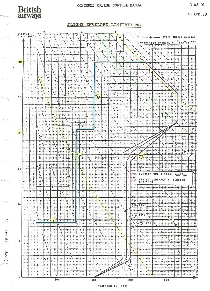
For convenience, I repeat Bellerophon's diagram of the flight envelope here.
Mike's earlier question had me scratching my head too, hence my question.
What are the fundamental reasons for each of the limitations, and what were the consequences of going outside them?
Going clockwise from the left, we have :
VLA (lowest admissible speed)
One would expect a curve for constant alpha max against IAS and altitude, not the staircase in the diagram.
Was this for simplicity of use of the diagram?
Max altitude (60,000ft)
This is the 'simplest' one: it was the highest 'safe' altitude from which an emergency descent could be made, in the case of a window blowing out, without having the blood of the pax boil....
Test flights (without pax, and with the crew pressure-breathing oxygen) did go as high as 69,000ft.
Mmo (max operating Mach number)
Mach 2.04 is usually quoted as having been chosen to assure an adequate life of the airframe.
But what effect does a higher Mach number as such have?
Or are Mmo and Tmo (127\xb0C) directly related?
Vmo (max operating speed) = 530kts until 43,000ft
I suppose this is related to structural limits (qmax)?
Vmo reducing to 380/400kts at about 33,000ft
What is the limiting factor here (other than qmax)?
Vmo constant at 380/400kts down to 5,000ft
What is the limiting factor here? The answer will no doubt also explain why this is slightly weight-dependent.
Vmo reducing to 300kts between 5,000ft and 0 ft
Why the sudden change below 5,000ft?
CJ
26th Dec 2010, 18:47
permalink Post: 1020
[quote=ChristiaanJ]
VLA (lowest admissible speed)
One would expect a curve for constant alpha max against IAS and altitude, not the staircase in the diagram.
Was this for simplicity of use of the diagram?[quote]
I don't have a complete explanation for all the regions - it was a long time ago and I'll need to dig, but:
Below 16000 ft Vla obviously needs to go as low as Vref to cover landing at elevated airfield altitudes. At present I don't have a satisfactory explanation for 250 kts between 16000 ft and about 45000 ft (250kts/Mach 1.0) A constant value in IAS is what you would get for a constant CLmax (the alphamax is not really the driver). Vla should give a margin above stall, and a quick sum suggests that 250 kts would be consistent with a 1.3Vs condition and a CLmax of about 0.8 up to Mach 1.0, which is not unreasonable, but I am not saying that is the correct interpretation.
From 45000 ft to 60,000 ft I think Vla may be set by manoeuvre requirements. Certainly the forward CG envelope boundary between 1.0M and 1.5M discussed in earlier posts is very close to the requirement to be able to pull 1.2g with half hinge moment available at Vla and heavy weights. Again not certain, but best guess at the moment.
Yes
[quote ]Mmo (max operating Mach number)
Mach 2.04 is usually quoted as having been chosen to assure an adequate life of the airframe.
But what effect does a higher Mach number as such have?
Or are Mmo and Tmo (127\xb0C) directly related?[quote]
I have always been puzzled by this statement as one does not normally associate Mach Number with a life limit. Going through my collection of lectures I found another, more plausible explanation:
quote" The scheduled cruise mach Number was 2.0. associated with a structural total temperature of 400 degK. Above ISA +5 Mc was cut back to maintain 400 degK.
To cope with variations of flight mach Number about Mc associated with often rapid and significant changes in wind and temperature which occur particularly in the vicinity of the tropopause (which can of course be as high as 60,000 ft in the tropics) a maximum operating Mach Number (Mmo) of 2.04 is selected" unquote [Leynaert, Collard and Brown, AGARD Flight Mechanics Symposium October 1983]
This is much more in line with my memory on this subject.
Yes in principle, but it is a bit chicken and egg, since 530 kts also represents a very good choice for best performance, and I am sure that the stucture would have been built to cope if a higher speed was needed for performance reasons. To the best of my knowledge there is no structural design case that would be critical in this flight regime (other than flutter of course)
Same as earlier - transonic manoeuvre requirements with failed hydraulics, matched to aircraft weight and CG envelope possibilities.
Same again.
I'm not entirely sure, but:
a) there is absolutely no advantage is having a high Vmo at low altitudes as it could not be exploited even if one wanted to because of ATC limitations to 250 kts below 10,000 ft (in the USA at least)
b) there are a lot of things that get rapidly worse if you encounter them at high speed and which are anyway more likely at low altitude - hail, birds etc.
So why store up trouble for yourself!
CliveL
One would expect a curve for constant alpha max against IAS and altitude, not the staircase in the diagram.
Was this for simplicity of use of the diagram?[quote]
I don't have a complete explanation for all the regions - it was a long time ago and I'll need to dig, but:
Below 16000 ft Vla obviously needs to go as low as Vref to cover landing at elevated airfield altitudes. At present I don't have a satisfactory explanation for 250 kts between 16000 ft and about 45000 ft (250kts/Mach 1.0) A constant value in IAS is what you would get for a constant CLmax (the alphamax is not really the driver). Vla should give a margin above stall, and a quick sum suggests that 250 kts would be consistent with a 1.3Vs condition and a CLmax of about 0.8 up to Mach 1.0, which is not unreasonable, but I am not saying that is the correct interpretation.
From 45000 ft to 60,000 ft I think Vla may be set by manoeuvre requirements. Certainly the forward CG envelope boundary between 1.0M and 1.5M discussed in earlier posts is very close to the requirement to be able to pull 1.2g with half hinge moment available at Vla and heavy weights. Again not certain, but best guess at the moment.
Quote:
|
Max altitude (60,000ft)
This is the 'simplest' one: it was the highest 'safe' altitude from which an emergency descent could be made, in the case of a window blowing out, without having the blood of the pax boil.... Test flights (without pax, and with the crew pressure-breathing oxygen) did go as high as 69,000ft. |
[quote ]Mmo (max operating Mach number)
Mach 2.04 is usually quoted as having been chosen to assure an adequate life of the airframe.
But what effect does a higher Mach number as such have?
Or are Mmo and Tmo (127\xb0C) directly related?[quote]
I have always been puzzled by this statement as one does not normally associate Mach Number with a life limit. Going through my collection of lectures I found another, more plausible explanation:
quote" The scheduled cruise mach Number was 2.0. associated with a structural total temperature of 400 degK. Above ISA +5 Mc was cut back to maintain 400 degK.
To cope with variations of flight mach Number about Mc associated with often rapid and significant changes in wind and temperature which occur particularly in the vicinity of the tropopause (which can of course be as high as 60,000 ft in the tropics) a maximum operating Mach Number (Mmo) of 2.04 is selected" unquote [Leynaert, Collard and Brown, AGARD Flight Mechanics Symposium October 1983]
This is much more in line with my memory on this subject.
Quote:
|
Vmo (max operating speed) = 530kts until 43,000ft
I suppose this is related to structural limits (qmax)? |
Quote:
|
Vmo reducing to 380/400kts at about 33,000ft
What is the limiting factor here (other than qmax)? |
Quote:
|
Vmo constant at 380/400kts down to 5,000ft
What is the limiting factor here? The answer will no doubt also explain why this is slightly weight-dependent. |
Quote:
|
Vmo reducing to 300kts between 5,000ft and 0 ft
Why the sudden change below 5,000ft? |
a) there is absolutely no advantage is having a high Vmo at low altitudes as it could not be exploited even if one wanted to because of ATC limitations to 250 kts below 10,000 ft (in the USA at least)
b) there are a lot of things that get rapidly worse if you encounter them at high speed and which are anyway more likely at low altitude - hail, birds etc.
So why store up trouble for yourself!
CliveL
21st Apr 2011, 16:53
permalink Post: 1307
I hate to go back several pages, but I still have a basic question about the lift generation when the AoA was more moderate.
When not generating vortex lift, was the airflow attached over both the upper and lower wing surface?
The mental picture I have is that during supersonic flight and also during subsonic but high-IAS phases, the wing was generating lift in a way Newton and Bernoulli would have immediately recognized. As the IAS decreased and AoA increased, the vortex started at the leading edge, and gradually grew in both size and contribution to overall lift until the vortex (or vortices) accounted for all the lifting force.
21st Apr 2011, 17:44
permalink Post: 1308
Quote:
|
When not generating vortex lift, was the airflow attached over both the upper and lower wing surface?
As the IAS decreased and AoA increased, the vortex started at the leading edge, and gradually grew in both size and contribution to overall lift until the vortex (or vortices) accounted for all the lifting force. |
The vortices never provided all the lifting force. Up to about 6 or 7 deg AoA there was no vortex lift, just the usual wing tip vortices. Above that AoA the non-linear (vortex) lift grew steadily until at stall (about 23 deg AoA) the vortex lift was around 45% of the total.
12th Jun 2011, 16:26
permalink Post: 1381
What was the minimum maneuvering speed for Concorde
It was expressed in the flight manual as "Lowest Authorised" speed, Vla, and didn't depend on weight. 0-15,000' Vla=V2 or Vref as appropriate, 15,000'-41,000' Vla=250kias, 41,000'-60,000' Vla=300kias
Also what was the typical climb speed I'm guessing you mean rate of climb rather than IAS?
- At lift-off? From memory Vr was around 200kts, V2 around 220kts and if restricted to 250kts (way below min drag) you'd get pretty poor rates of climb - about 1000fpm if you were lucky and IIRC - you'd quickly want to lower the nose, just barely climb and get her up to 400kts when she'd really fly...
- Once 240 kts is achieved? see above - but once you got her up to min drag (about 400kts at MTOW) things went better - about 4000fpm without reheat
- At minimum maneuvering speed at typical takeoff weight? At V2 she staggered up due the the drag of the slender delta wing at low IAS - but climb performance on three engines (in contingency reheat) at V2/MTOW was better than a conventional subsonic jet on three / MTOW / V2 due to conservative certification requirements of the TSS
- At MTOGW? Does the above answer your Q? Happy to add more if you need...
Edited to add, most transatlantic takeoffs were at MTOW - around 185 tonnes - and due to the slender delta aerodynamics, weight didn't affect performance as much as a conventional wing anyway because induced drag was the bigger player at slow speeds - and I've just completely exhausted my very limited grasp of aerodynamic engineering!!
22nd Jun 2011, 22:24
permalink Post: 1395
NW1
I assume in the US then you were restricted to 250 kts below 10,000 feet just like all other aircraft?
Why higher speed? That have to do with shockwaves and the resulting pressure distribution differences?
No, I meant the airspeed you'd be flying at while climbing (post takeoff)
Wow, that's pretty bad. You'd figure with a T/W ratio of around 0.40 you'd do far better than most other aircraft.
Were you allowed to get over 250 below 10,000 feet in the US, or UK? Regardless, what rate of climb would you get at that speed?
408,000 pounds?
Quote:
| It was expressed in the flight manual as "Lowest Authorised" speed, Vla, and didn't depend on weight. 0-15,000' Vla=V2 or Vref as appropriate, 15,000'-41,000' Vla=250kias |
Quote:
| 41,000'-60,000' Vla=300kias |
Quote:
| I'm guessing you mean rate of climb rather than IAS? |
Quote:
| if restricted to 250kts (way below min drag) you'd get pretty poor rates of climb - about 1000fpm if you were lucky |
Quote:
| and IIRC - you'd quickly want to lower the nose, just barely climb and get her up to 400kts when she'd really fly... |
Quote:
| most transatlantic takeoffs were at MTOW - around 185 tonnes |
24th Jun 2011, 00:15
permalink Post: 1399
<<
I'm guessing you mean rate of climb rather than IAS?
>>
<<No, I meant the airspeed you'd be flying at while climbing (post takeoff)>>
OK, then the answer to your Q's:
Also what was the typical climb speed
- At lift-off? About 200kts
- Once 240 kts is achieved? 240kts
- At minimum maneuvering speed at typical takeoff weight? Vla after takeoff was V2 until 15,000'. I.E. about 220kts
- At MTOGW? V2 didn't vary much by weight
Out of JFK we flew at Vmo once further than 12nms from the coast. Vmo=400kts IAS at low level.
Out of LHR overland the IAS restriction was 300kts until past the speed limit point early in the SID - much less draggy than 250kts and hence better climb rates. But you'd quickly be released to get to 400kts (barder's pole) where it was designed to be flown.
<<Why higher speed? That have to do with shockwaves and the resulting pressure distribution differences?>>
The flight envelope was bigger and more complex than subsonic types: it was developed in flight test and probably had many considerations involved. I think someone posted it earlier in this thread in graphical form (from the flight manual) if you want to see it. In practice, you had to be aware of three basic parameters - IAS, Mach and CG position (the CG "corridor"). Once understood, it wasn't that difficult to keep up with it...and the IAS and Machmeters had barber's poles handily programmed to show the limiting values (including, cleverly, max temp on the nose Tmo=127 degrees celcius).
Regarding climb rates - best ROC was at 400kts (MTOW) or 380kts (MLW). As speed reduced below that, drag increased and ROC reduced. At MTOW and 400kts you'd get about 4000fpm max dry power. At 250kts it was all noise and very few feet per minute - after noise abate procedures you had to lower the nose, just barely climb, and get IAS up toward min drag as soon as possible. With an engine failed go for 300kts minimum - Vmo as soon as you can.
<<shockwaves and the resulting pressure distribution differences>>
You had to avoid the "transonic" region due to these effects: maximum subsonic cruise was 0.95M due to the auto-stabilised flying controls become over-active as shockwaves started to "dance" around the airframe (usually asymmetrically). This calmed down by about 1.3M in the acceleration (when the intake ramps started to do their thing). To accelerate to 2.0M you needed reheat until 1.7M so you didn't hang around between 0.95M and 1.7M. FL260 was best for subsonic cruise because at that level 400kts IAS = 0.95M...
Last edited by NW1; 24th Jun 2011 at 09:09 .
27th Apr 2012, 17:17
permalink Post: 1601
There's a question (OK, 2) I wonder if those on here can answer.
1) I undertsnd that skin temperature is calculated from OAT and Mach number. Why wasn't it simply measured directly by sensors on the nose skin?
2) The Air Data Computer calculates Mach (so skin temp is a calculation on a calculation!). Presumably one parameter it uses is IAS. What else is used in the calculation of Mach?
30th Nov 2012, 15:22
permalink Post: 1693
A couple of questions
Hi all, amazing thread! I hope I can add a couple of autopilot questions:
1. Did anyone ever use the IAS Hold button in the vertical mode, i.e. control speed with pitch instead of autothrottle? I always thought it might be used during climbout to maintain 250 knots under 10000 feet at full throttle.
2. How did the autopilot work in 'Go Around' mode and was it ever used, or were go arounds always done manually?
Thanks in advance,
Jim
Last edited by taichi40; 30th Nov 2012 at 15:37 .