17th Nov 2010, 03:44
permalink Post: 718
Hello all to all members and Concorde Expert,
I have been read this thread and it is so great. I'm enjoy reading it all day long!!
I have some question that I'm wonder about the Concorde.
1. I've heard that Concorde use the primary nozzle to modulate the noise and
the speed of the N1 compressor. How does it work? and does it help to reduce
the noise a lot?
2.Another thing about Primary nozzle. If i recall it correctly, the primary nozzle
can also use to control the Inlet Turbine temperature. Is that true? How is that work?
3.Finally, does some one have a schematic or the fuel vent system?
That's all of it. I will transform in to a nerd man reading a Concorde book in
the next couple days.
Thanks for all of yours reply.
18th Nov 2010, 00:32
permalink Post: 719
Mr Vortex
First of all, 'welcome aboard'; I'll do my best to answer your queries.
The area of the primary nozzle Aj, was varied for 2 'primary' purposes :
:
a) To act as a military type 'reheat' or 'afterburning' nozzle; opening up to control the rise in jet pipe pressure P7, as reheat is in operated.
b) To match the INLET TOTAL TEMPERATURE RELATED (T1) speed of the LP compressor N1 to the HP compressor N2 against a series of schedules, ensuring easch spool is as close as safely possible to its respective surge boundary, (with a constant TET, see below) and therefore at peak efficiency.
Now, in doing this a complex set of variables were in place. As the nozzle is opened there is a REDUCED pressure and temperature drop across the LP turbine. This has the effect of enabling a HIGHER N1,as less work is being done by the turbine. Also the change (in this case a decrease) in the temperature drop across the turbine will obviously affect the turbine entry temperature, TET. A closing down of the nozzle would obviously have the opposite effect, with a DECREASE in N1 and an INCREASE in TET.
In practice at a given T1 there was always an ideal N1 versus N2 on the control schedule (known as the E Schedule), the TET staying more or less constant from TAKE-OFF to SUPERSONIC CRUISE!!
As far as noise abatement went; when reheat was cancelled and power reduced after take-off, an E Schedule known as E Flyover was automatically invoked. This had the effect of driving the primary nozzle nearly wide open, reducing both the velocity of the jet efflux and in essence the noise below the aircraft.
The real beauty of this primary nozzle system was that it really did not care if the engine was operating dry or with afterburning ('it' did not even know). P7 was controlled against a varying compressor outlet pressure, the variable being controlled by a needle valve operated by the electronic engine controller. (If this is unclear I can post a diagram here that shows this control in action).
As soon as I receive back the majority of my technical notes that I have out on long-term loan (I've requested their return) I will post a schematic here. But for now; The tanks were vented to atmosphere via tandem vent galleries, the two vents openings being on the left hand side of the tail-cone. At an absolute static pressure of 2.2 PSIA (around 44,000') twin electrically operated vent valves, also in the tail-cone, would automatically close; the tanks now being pressurised via a small NACA duct on the right side of the fin. A tank pressure of around 1.5 PSIG was maintained by the action of a small pneumatic valve at the rear of the aircraft. There was massive protection built in to guard against over-pressure (eg. if a tank over-filled in cruise).
I hope this answers some of your queries
Best Regards
Dude
Quote:
|
1. I've heard that Concorde use the primary nozzle to modulate the noise and the speed of the N1 compressor. How does it work? and does it help to reduce the noise a lot?
2.Another thing about Primary nozzle. If i recall it correctly, the primary nozzle can also use to control the Inlet Turbine temperature. Is that true? How is that work |
The area of the primary nozzle Aj, was varied for 2 'primary' purposes
:
a) To act as a military type 'reheat' or 'afterburning' nozzle; opening up to control the rise in jet pipe pressure P7, as reheat is in operated.
b) To match the INLET TOTAL TEMPERATURE RELATED (T1) speed of the LP compressor N1 to the HP compressor N2 against a series of schedules, ensuring easch spool is as close as safely possible to its respective surge boundary, (with a constant TET, see below) and therefore at peak efficiency.
Now, in doing this a complex set of variables were in place. As the nozzle is opened there is a REDUCED pressure and temperature drop across the LP turbine. This has the effect of enabling a HIGHER N1,as less work is being done by the turbine. Also the change (in this case a decrease) in the temperature drop across the turbine will obviously affect the turbine entry temperature, TET. A closing down of the nozzle would obviously have the opposite effect, with a DECREASE in N1 and an INCREASE in TET.
In practice at a given T1 there was always an ideal N1 versus N2 on the control schedule (known as the E Schedule), the TET staying more or less constant from TAKE-OFF to SUPERSONIC CRUISE!!
As far as noise abatement went; when reheat was cancelled and power reduced after take-off, an E Schedule known as E Flyover was automatically invoked. This had the effect of driving the primary nozzle nearly wide open, reducing both the velocity of the jet efflux and in essence the noise below the aircraft.
The real beauty of this primary nozzle system was that it really did not care if the engine was operating dry or with afterburning ('it' did not even know). P7 was controlled against a varying compressor outlet pressure, the variable being controlled by a needle valve operated by the electronic engine controller. (If this is unclear I can post a diagram here that shows this control in action).
Quote:
3.Finally, does some one have a schematic or the fuel vent system?

|
I hope this answers some of your queries
Best Regards
Dude
29th Nov 2010, 09:01
permalink Post: 808
Dude, only 5 seconds ?? I'd demand a re-edit mate...outrageous !

Out of interest...here is a pic of AG in Seattle ( taken a while back ) and the source of a big part of this thread - unfortunately could not get any higher in order to get a better view...on either end ! ( I need to check on her again and see how she is doing ) and the SR71 also ( from the Pima Air / Space museum in Arizona) - I am sure all have seen the Concorde intakes but the SR71 rear end is interesting....
ps Please forgive the pic of the Sikorsky ( at Pima also ) ...couldnt resist
Cheers...
30th Nov 2010, 10:16
permalink Post: 820
Hi DavvaP, and welcome. As far as ice on the wing goes, I'm sure as any of my pilot friends here will agree that she was treated just like a subsonic in that regard; any ice or snow build up on the surfaces of the wings would not be tolerated and would have to be removed before flight. (She may have had a revolutionary wing design, but still this was a wing nonetheless
 ). She would also require pre-flight chemical anti-icing/de-icing treatment from a ground truck just like the rest, in shall we say, 'less than tropical conditions'. (Winters in Prestwick during crew base training... such fond memories


 ). As far as active ice protection on the wings, there was a highly sophisticated Lucas electrical 'spraymat' system fitted, but only the wetted areas of the wing, forward of the engines were 'covered'. Two digitall cyclic timers (CTPUs) would automatically regulate cyclic switching on and off of 115 VAC for various load areas of the wing at a time at pilot pre-selectable intervals (2, 4 or 8 seconds). Also as part of this system, there was
continuous
de-icing for certain other load areas too, so you had a mix of cyclic and continuous de-icing in operation. The whole idea here was to prevent chunks of ice entering and damaging the engines, the only other areas of this electrical de-icing system were the intake lips and side-walls and also the D Box area above the auxilliary inlet vane, built into the spill door. (This would only operate if the auxilliary inlet door itself was open). The whole shooting match would automatically switch itself off, for obvious reasons, above a TAT of 15\xb0 C. (ie. the vast majority of the flight). The only other de-icing system (apart from the galley drain masts) was on the engine inlet guide vanes, but this was purely pneumatic and again would swith itself off above 15\xb0 C.
). As far as active ice protection on the wings, there was a highly sophisticated Lucas electrical 'spraymat' system fitted, but only the wetted areas of the wing, forward of the engines were 'covered'. Two digitall cyclic timers (CTPUs) would automatically regulate cyclic switching on and off of 115 VAC for various load areas of the wing at a time at pilot pre-selectable intervals (2, 4 or 8 seconds). Also as part of this system, there was
continuous
de-icing for certain other load areas too, so you had a mix of cyclic and continuous de-icing in operation. The whole idea here was to prevent chunks of ice entering and damaging the engines, the only other areas of this electrical de-icing system were the intake lips and side-walls and also the D Box area above the auxilliary inlet vane, built into the spill door. (This would only operate if the auxilliary inlet door itself was open). The whole shooting match would automatically switch itself off, for obvious reasons, above a TAT of 15\xb0 C. (ie. the vast majority of the flight). The only other de-icing system (apart from the galley drain masts) was on the engine inlet guide vanes, but this was purely pneumatic and again would swith itself off above 15\xb0 C.
I think you will find that precious little of Concorde is now not generally available in the public domain, some control software and laws are still I would expect covered by some sort of patent. (That is why when I publiished here the engine 'E Schedule' graphs I deliberately deleted the equations for the various running lines.
Your efficiency question was a valid one; as IAS and Mach number increase the aerodynamic drag (in all it's forms) will generally increase, but the efficiency OF A WELL DESIGNED powerplant wil also increase, and Concorde was definately no exception here. The real beauty of Concorde was just HOW MUCH the powerplant efficiency increased with increasing speed and more than totally eclipsed the aerodynamic drag rise with this increasing speed. At supersonic speeds, the closer you could fly to Vmo/Mmo the lower the fuel burn was. (Especiall true at Mach 2, although the autopilot would hold you Mach 2 (ish) in Max Cruise mode, flying closer to Mmo, Mach 2.04, would save fuel, assuming the static air temoerature was low enough to sustain this). This fact (along with about a million others) produced what we all like to call 'The Magic of Concorde'
Best Regards
Dude
). She would also require pre-flight chemical anti-icing/de-icing treatment from a ground truck just like the rest, in shall we say, 'less than tropical conditions'. (Winters in Prestwick during crew base training... such fond memories
). As far as active ice protection on the wings, there was a highly sophisticated Lucas electrical 'spraymat' system fitted, but only the wetted areas of the wing, forward of the engines were 'covered'. Two digitall cyclic timers (CTPUs) would automatically regulate cyclic switching on and off of 115 VAC for various load areas of the wing at a time at pilot pre-selectable intervals (2, 4 or 8 seconds). Also as part of this system, there was
continuous
de-icing for certain other load areas too, so you had a mix of cyclic and continuous de-icing in operation. The whole idea here was to prevent chunks of ice entering and damaging the engines, the only other areas of this electrical de-icing system were the intake lips and side-walls and also the D Box area above the auxilliary inlet vane, built into the spill door. (This would only operate if the auxilliary inlet door itself was open). The whole shooting match would automatically switch itself off, for obvious reasons, above a TAT of 15\xb0 C. (ie. the vast majority of the flight). The only other de-icing system (apart from the galley drain masts) was on the engine inlet guide vanes, but this was purely pneumatic and again would swith itself off above 15\xb0 C.
I think you will find that precious little of Concorde is now not generally available in the public domain, some control software and laws are still I would expect covered by some sort of patent. (That is why when I publiished here the engine 'E Schedule' graphs I deliberately deleted the equations for the various running lines.
Your efficiency question was a valid one; as IAS and Mach number increase the aerodynamic drag (in all it's forms) will generally increase, but the efficiency OF A WELL DESIGNED powerplant wil also increase, and Concorde was definately no exception here. The real beauty of Concorde was just HOW MUCH the powerplant efficiency increased with increasing speed and more than totally eclipsed the aerodynamic drag rise with this increasing speed. At supersonic speeds, the closer you could fly to Vmo/Mmo the lower the fuel burn was. (Especiall true at Mach 2, although the autopilot would hold you Mach 2 (ish) in Max Cruise mode, flying closer to Mmo, Mach 2.04, would save fuel, assuming the static air temoerature was low enough to sustain this). This fact (along with about a million others) produced what we all like to call 'The Magic of Concorde'
Best Regards
Dude
Last edited by M2dude; 30th Nov 2010 at 12:21 .
1st Dec 2010, 14:04
permalink Post: 822
Well I have to say this is a brilliant thread.
I stumbled upon it by accident and been catching up on it when I had a spare moment and have found it completely riveting and it has whiled away many hours over the past month.
I\x92m ex-RAF and spent the last ten years working as an engine bloke on the T aeroplane & RB199. We were always told there were many parallels with Concorde & the Olympus 593 \x96 TBT/T7 Gauges, Optical Pyrometers, EPC Coils on-engine FCU\x92s, Vapour Core Pump for reheat fuel as well and the like. I attended the RR Manufactures course for two weeks at the Patchway Works and spent a day at the Concorde Museum seeing the similarities with the Electronic Control Units too though Lucas Aerospace made the MECU\x92s or GR1/4 (& DECU\x92s on the F3\x92s).
Also while on the course the distinguished RR Instructor Gent filled up in with various snippets of Engine History too such as the Vaporisers which were fitted to RB199 & the later models of Olympus 593 were originally Armstrong Sidderly designed for the Sapphire, also I learned the whole 15 Stage Sapphire Compressor was lifted completely and fitted to later Avon\x92s as it worked better.
I was at Leuchars in the early 80\x92s and the Open Golf peeps all arrived in one of these magnificent lady\x92s \x96 the visit was notable for several things; someone fired off an escape chute!!! \x96 What does this little handle do on the Main Oleo ??? whoosh ! and after the dusk take off the pilot beat the place up several times in full reheat !!!!
My last place of work before I was de-mobbed was at the RAF Marham Engine bay and I had the good fortune to meet an RR Technician called Phil (second name escapes me) but he was part of the team of RR Controls Engineers during the Hot & High Trials. He said they used to modify the three \x93Amps\x94 for each Engine control \x96 Lane1, Lane 2 & Reheat on the fly and the aircraft often flew with different schedules installed on all four engines \x96 I think the aircraft at Duxford has these still fitted in the racks (??M2Dude??) but that\x92s another Tonka thing too; three control lanes. Were all these Amps combined into one black box??
They are always Amps in RR Speak?? The Spey 202 had \x93Amps\x94 in its reheat system too.
I was lucky to find a job with the TVOC in 2001 until they ran out of money (as they do) and worked to have their flight worthy Olympus 20202\x92s tested at RR Ansty but left before that happened. In fact I don\x92t know if it did happen though it was a CAA requirement. While I was there we were working with Alan Rolfe & Mike Batchelor of the RR Historic Engine Department were offering support too. (593\x92s were their responsibility also !!! Historic !!!) but I think that was unofficial until there was an agreement about the costs.
After that I worked in industrial applications of Olympus (and Avon) and worked on many installed Olympus in power generation but based on the 200 Series \x96 I think the 300 was thought to be too fragile. But I did have a good look at Olympus 2008/003 Still in good working order in Jersey on the Channel Islands with it\x92s Bristol Sidderly Name plate on it. They didn't have Inlet Guide Vanes as the 300's had but just 6 Forward Bearing Supports, hollow with anti -Icing air blown though, controlled by a Garret Air Valve.
I never saw a DEBOW sort of function on the Industrials but there is a critical N1 speed which has to be avoided because the LP Turbine Disc can fail. The Trouble with that speed range is that it is right where the usefull power is produced!!! Was there any Normal Operating Range RPM's which had to be avoided on the 593 ?
Again thanks very much for all the fascinating information here\x92s to another 42 pages!!
Sorry to have rambled on so much

Howie
I stumbled upon it by accident and been catching up on it when I had a spare moment and have found it completely riveting and it has whiled away many hours over the past month.
I\x92m ex-RAF and spent the last ten years working as an engine bloke on the T aeroplane & RB199. We were always told there were many parallels with Concorde & the Olympus 593 \x96 TBT/T7 Gauges, Optical Pyrometers, EPC Coils on-engine FCU\x92s, Vapour Core Pump for reheat fuel as well and the like. I attended the RR Manufactures course for two weeks at the Patchway Works and spent a day at the Concorde Museum seeing the similarities with the Electronic Control Units too though Lucas Aerospace made the MECU\x92s or GR1/4 (& DECU\x92s on the F3\x92s).
Also while on the course the distinguished RR Instructor Gent filled up in with various snippets of Engine History too such as the Vaporisers which were fitted to RB199 & the later models of Olympus 593 were originally Armstrong Sidderly designed for the Sapphire, also I learned the whole 15 Stage Sapphire Compressor was lifted completely and fitted to later Avon\x92s as it worked better.
I was at Leuchars in the early 80\x92s and the Open Golf peeps all arrived in one of these magnificent lady\x92s \x96 the visit was notable for several things; someone fired off an escape chute!!! \x96 What does this little handle do on the Main Oleo ??? whoosh ! and after the dusk take off the pilot beat the place up several times in full reheat !!!!
My last place of work before I was de-mobbed was at the RAF Marham Engine bay and I had the good fortune to meet an RR Technician called Phil (second name escapes me) but he was part of the team of RR Controls Engineers during the Hot & High Trials. He said they used to modify the three \x93Amps\x94 for each Engine control \x96 Lane1, Lane 2 & Reheat on the fly and the aircraft often flew with different schedules installed on all four engines \x96 I think the aircraft at Duxford has these still fitted in the racks (??M2Dude??) but that\x92s another Tonka thing too; three control lanes. Were all these Amps combined into one black box??
They are always Amps in RR Speak?? The Spey 202 had \x93Amps\x94 in its reheat system too.
I was lucky to find a job with the TVOC in 2001 until they ran out of money (as they do) and worked to have their flight worthy Olympus 20202\x92s tested at RR Ansty but left before that happened. In fact I don\x92t know if it did happen though it was a CAA requirement. While I was there we were working with Alan Rolfe & Mike Batchelor of the RR Historic Engine Department were offering support too. (593\x92s were their responsibility also !!! Historic !!!) but I think that was unofficial until there was an agreement about the costs.
After that I worked in industrial applications of Olympus (and Avon) and worked on many installed Olympus in power generation but based on the 200 Series \x96 I think the 300 was thought to be too fragile. But I did have a good look at Olympus 2008/003 Still in good working order in Jersey on the Channel Islands with it\x92s Bristol Sidderly Name plate on it. They didn't have Inlet Guide Vanes as the 300's had but just 6 Forward Bearing Supports, hollow with anti -Icing air blown though, controlled by a Garret Air Valve.
I never saw a DEBOW sort of function on the Industrials but there is a critical N1 speed which has to be avoided because the LP Turbine Disc can fail. The Trouble with that speed range is that it is right where the usefull power is produced!!! Was there any Normal Operating Range RPM's which had to be avoided on the 593 ?
Again thanks very much for all the fascinating information here\x92s to another 42 pages!!
Sorry to have rambled on so much
Howie
5th Dec 2010, 06:11
permalink Post: 835
More Olympus stuff
Greetings.
Service Bulletin 0420 Industrial Olympus Gas Generator \x96 LP Turbine Disc Cracking Safety Related Operational and inspection requirements.
to paraphrase:
Avoid steady operations in the range 5450 to 5850 RPM I believe that 100% is 8000RPM so that equates to 68 \x96 73%. It is ok the accelerate through that range apparently.
There seems to be a lot of history about Olympus LP Discs:
Test House 40 \x96 I think - at RR Ansty still has the deep groves in the brickwork where an engine broke up during test.
From Wikipedia:
\x93XA894 flew with five Olympus engines, the standard four plus an underbelly supersonic Olympus 320 fed from a bifurcated intake starting just aft of the wing leading edge and inboard of the main intakes, in a mock-up of the BAC TSR-2 installation. This aircraft was destroyed on a fire on the ground on 3 December 1962\x94
I read the LP Disc did a QANTAS A380 and decided to leave the engine:
An Aviation Heritage story
So there\x92s nothing new in the world really
regards
HH93
Last edited by howiehowie93; 5th Dec 2010 at 07:19 .
5th Dec 2010, 12:44
permalink Post: 837
why was the Olympus so suitable
Quote:
| what was it about the Olympus that made it so capable in so many guises and for so long? |
All these engines from other manufacturers have complicated systems to make them efficient:
VIGV's (Variable Inlet Guide Vanes)
VSV's (Variable Stator Vanes)
Bleed Valves
Multi Fuel Metering Valves & other valves to keep emissions under control.
The Olympus - nowt ! Two Spools and a Fuel Valve thats your lot. nothing to go wrong and being an Aeroderivative all the ancillary equipment is either bolted on underneath or away from the engine outside the enclosure.
The only thing I had trouble with was the burner bolts shearing off, 1/4"BSF, if never touched in a good few years !
Was it all still BSF on the 593? That was a Bristols thing - true RR designs are UNC (well Avons are anyway)
oh ! I forgot about the Hot Shot; when I was ground running installed RB199's there was no jump in TBT/T7, you couldn't sense it fire either, the only feel was either the Reheat lighting off with a big roar or the engine going quiet as the Nozzle opened up until the MECU noticed it hadn't lit and closed it again sharpish.
Good eh
Regards
H
 wie
wie
Last edited by howiehowie93; 5th Dec 2010 at 13:25 . Reason: Hot Shot paragraph added. Also SPELLING !! see me after school.
11th Dec 2010, 20:59
permalink Post: 855
Quote:
|
Originally Posted by
dixi188

A certain CFI (I think) at BA flying club, High Wycombe, who was also F/O on concorde, showed me some photographs of an engine that had eaten a piece of intake ramp.
I think he said that the adjacent engine had surged and a piece of ramp went out the front and down the other engine. This resulted in a double engine failure mid atlantic. They landed in Shannon with very little fuel left. |
First time that happened was on prototype 001 in the very early days, when an engine "spit out" the entire ramp (there's a photo in Trubshaw's book).
The ramps and actuators were 'beefed up' considerably afterwards... I didn't know an in-service aircraft had suffered a similar mishap.
Quote:
| Question, how fast was the ramp going if the A/C was at Mach 2? |
CJ
PS I have no record of any of the British development aircraft ever having lost a ramp, notwithstanding the number of deliberate engine surges they went hrough. But then maybe I wasn't told....
11th Dec 2010, 22:17
permalink Post: 856
Hi Guys, quite a few little points here, so here's my angle(s):
Pedalz
Ooo yes. The biggest problems we ever had associated with the ramps themselves were wear in the seals at the sides of the forward ramp. Even a few thou' over the maximum allowable side gap was enough to make the intake unstable and susceptible to surging. (It is quite interesting that the rear ramp side gaps were not in the least bit critical, and if Concorde intake development had continued, the rear ramps were going to be deleted altogether). Other failure factors were control unit malfuntions, rapid sensor drift; all of these causing either ramp/spill door drift or runaway. Primary nozzle misbehaviour could also result in intake surges. Having said all that, the monitoring of the intake system was truly superb, and surface runaways, themselves quite rare, would usually be picked up by the control system monitors causing either a lane switch or if that did not work, a total 'red light' failure with the surfaces frozen. No surge was treated as 'just one of those things', and much midnight oil was burned and hair pulled out (so that's what happened to mine
 ) to try and find the cause of the surge.
My friend EXWOK perfectly answered the intake hydraulics allocations.
EXWOK was right on the ball here as usual, in fact above Mach 1.6 an interactive surge was more or less guaranteed. The cause of interactive surge had nothing to do with the wing leading edge position, but to the radially generated distortion field coming out of the FRONT of the surging intake, severely distorting the adjascent intakes airflow. It mattered not if the originating surge was an inboard or an outboard intake, the other guy would always go also, above Mach 1.6.
You might want to take a look at 'When Intakes Go Wrong Part 1:
Concorde engine intake "Thrust"
and Parts 2 & 3:
Concorde engine intake "Thrust"
Not to mention Part 3:
dixi188
I can never recall this particular event happening with BA , certainly not as a result of a ramp failure. Although in the near 28 years of operation we had quite a few SNN diversions, none that I can ever recall were as the result of a ramp structural failure. The two major SNN diversions that I can recall were G-BOAF in the early 80s when an LP1 blade failed and resulted in a totally wrecked engine (although a completely contained failure) and G-BOAA in 1991, with another wrecked engine due to running in rotating stall. (Both of these events were covered previously in our thread). ChristiaanJ has mentioned quite rightly the event with A/C 001 spitting a ramp out, and Air France had a ramp failure going into JFK. (Covered previously in our thread, due to certain 'human foul ups'). I am not sure, but I think that
this
one in JFK DID require a double engine change in JFK. (Usually from SNN a BA aircraft would be 3 engine ferried back to LHR).
ChristiaanJ
Nope, you are quite right, no more French or British development aircraft ever suffered a ramp linkage failure again. The 001 ramp failure was a salutary lesson to the design team, and the intake assembly became tougher than old boots after that, nomatter WHAT you threw at it.
Due to the lateness of the hour (and me being up at 4
), that will have to do for now guys.
Best regards to all
Dude
Pedalz
Quote:
were the intake ramps in front of the engines ever known for problems? Especially during supersonic cruise where the airflow through the compressors and position of the ramps was determined by an exacting science which could turn into quite a situation if disturbed.
 Which hydraulic system actuated these ramps?
|
) to try and find the cause of the surge.
My friend EXWOK perfectly answered the intake hydraulics allocations.
Quote:
| Due to the shape of the leading edge and positioning of the intakes themselves, could it be possible that disturbed airflow from a problem ramp or donk could also effect it's outboard neighbour (if I'm right in presuming that only the inboard engine surging etc. could effect the outboard and not vice versa)?[/ |
You might want to take a look at 'When Intakes Go Wrong Part 1:
Concorde engine intake "Thrust"
and Parts 2 & 3:
Concorde engine intake "Thrust"
Not to mention Part 3:
dixi188
Quote:
| A certain CFI (I think) at BA flying club, High Wycombe, who was also F/O on concorde, showed me some photographs of an engine that had eaten a piece of intake ramp. I think he said that the adjacent engine had surged and a piece of ramp went out the front and down the other engine. This resulted in a double engine failure mid atlantic. They landed in Shannon with very little fuel left. |
ChristiaanJ
Quote:
|
PS I have no record of any of the British development aircraft ever having lost a ramp, notwithstanding the number of deliberate engine surges they went hrough. But then maybe I wasn't told....
|
Due to the lateness of the hour (and me being up at 4
), that will have to do for now guys.
Best regards to all
Dude
Last edited by M2dude; 12th Dec 2010 at 04:51 . Reason: Adding a bit and correcting another
12th Dec 2010, 16:28
permalink Post: 861
dixi188
This incident could well have been G-BOAD #2 engine then; this one swallowed an intake ramp brake assembly. Details of this incident itself can be found in the links that I posted regarding 'When Intakes Go Wrong'
Regards
Dude
.
This incident could well have been G-BOAD #2 engine then; this one swallowed an intake ramp brake assembly. Details of this incident itself can be found in the links that I posted regarding 'When Intakes Go Wrong'
Regards
Dude
.
20th Dec 2010, 06:11
permalink Post: 899
Quote:
| the limiting speed factor of the SR-71 was the wing leading edge temperature of 734 degrees |
Thread on the Concorde inlets here Concorde engine intake "Thrust"
24th Dec 2010, 13:02
permalink Post: 988
 Christian asked if there was an aerodynamicist in the house - I guess that would be me!
The original question was whether there was any vortex activity in subsonic cruise, but the discussion went on to ask about designing for subsonic drag I think.
The answer to the first bit is that the vortex flow started in a gentle manner from about 6 or 7 deg AoA and got steadily stronger. Depending on the chosen cruise speed and the aircraft weight, the subsonic cruise AoA would have been in the region of 4.5 to 5 degrees, i.e. below any significant vortex development. 6/7 deg would correspond to something in the range 250 to 280 kts probably (I haven't done the sums)
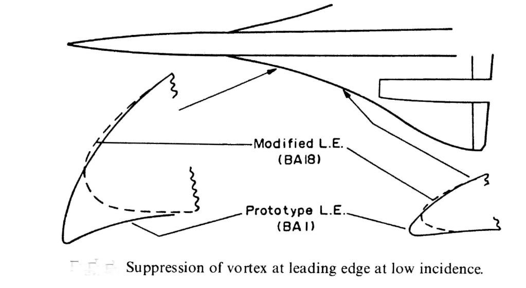
What we were trying to do for subsonic cruise was to have what is known in the trade as 'leading edge suction' acting on a nice bit of forward facing area so that it tried to drag the aircraft forwards as it were. As you can see from the diagram the prototype aircraft had a much more cambered LE so that both suction and forward facing area were very reasonable. This prototype shape was nicely rounded so that LE separation and top surface vortex generation started at a higher AoA than on the production aircraft. Unfortunately this shape, which featured a rather sharp LE on the undersurface, generated a vortex on the undersurface of the wing in supersonic flight and low AoA (near zero 'g'). This vortex got into the intake and caused the engine to surge, so we had to redesign the LE ahead of the intakes as shown. This cost us a little subsonic drag, so you can see from the diagram what you need to do to keep subsonic cruise drag down.
Hope this answers the questions
CliveL
24th Dec 2010, 21:35
permalink Post: 1003
Quote:
|
Originally Posted by
Landroger
I haven't needed to read a diagram like that in .... a whole grown up persons lifetime!
AND gates and OR gates, 'Op Amps' and an Exclusive OR, if I'm not mistaken? |
In my case, it's easier... I've become bitten by the Concorde bug again over the last ten years or so, and pulled dozens of similar diagrams from the documentation to refresh my memory.
Quote:
| Certainly it sounds, from time to time, that there were a million little black boxes dotted all over her airframe. |
Quote:
| I suspect however, that many of the 'terms' and 'laws' spoken about are simply a gate or two, perhaps an op' amp, placed in a larger circuit that modulates the output of that board, thus creating the law or term. |
Op-amps also were used for other functions such as demodulators (converting AC signals to DC) or comparators and level detectors.
I still mean to write some posts on "how to compute without a digital computer", but it'll have to wait until after the holidays.
Quote:
|
Digital control is a hell of a lot easier than Analogue - in my humble opinion.
|
In the 'olden' days we'd draw block diagrams like the one for the SFC, and once we agreed about all the functions we wanted, we just drew the schematics for each of the functions.
No sequencing, no real-time clock, no A/D or D/A conversion, no worries about cycle time or memory allocation. No programming-language issues, no naming of variables, no compiler faults, no software to debug.
You should try it sometime......
The major issue was, of course, that you ended up with a lot more hardware for the same functionalities, hence more weight, and more power consumption.
And the other issue, already alluded to in earlier posts, is that analogue computing is inherently not highly accurate.
In many cases of system control, a percent or two of precision is perfectly acceptable. But if a far higher precision is needed, like for instance in the intertial navigation system, or the core computing for the air intakes, only digital computing can do the job.
Seasons greetings to everyone on this thread from me too.
Christian
27th Dec 2010, 14:04
permalink Post: 1026
A pot pourri of responses after my Christmas reading!
This actually is interesting in that the n umbers show one of the fundamental features that made the Ol 593 such a good choice. If you look closely at the TO and cruise values you will find that at TO the overall compressor pressure ratio is 13.5 the compressor exit temperature 460 degC and the turbine inlet temperaure is 1152 degC. In cruise the pressure ratio is 10.5, the compressor exit is 565 degC and the TET 1100 degC.
Somebody, I can't find the exact post, was asking whether the elevated cruise total temperatures affected engine life, and here we see why this is so. As Christian said in another posting, when you compress air it gets hotter - from 21 degC to 460 degC at take off and from 127 degC to 565 degC in cruise. A fundamental limit on engine operation is the turbine entry temperature. Not only does it affect the maximum TO thrust you can get but also the continued exposure to cruise TETs has a very big effect on engine fatigue life, and engine manufacturers have shown extremes of ingenuity when developing new materials and ways of cooling the blades to increase allowable TET.
The problem with supersonic operations is that you start from an elevated intake delivery temperature so that when the flow exits the compressor it is already very hot 565 instead of 460 to be exact. But the maximum temperature one can stand for fatigue reasons is limited, therefore the amount of fuel you can pour in must be limited also, and the thrust you can develop per pound of airflow is roughly proportional to the fuel input/temperature rise. To get any sensible cruise thrust then one must squeeze the cruise TET as high as you dare for fatigue reasons but also you need to keep the compression ratio down so that the temperature going into the combustion chambers is as low as you can get away with. This tend to drive engines designed for extended supersonic operations to having a low pressure ratio. This is against the trend in subsonic operations where compression ratios have been steadily increasing along with bypass ratios.
The net result then is that the engine must be designed with a low OPR and must operate with cruise TET much closer to its TO TET value than would be necessary, or indeed desirable, on a subsonic design.
Actually, here, as on some other apparent carry-overs, one should look at the equipment supplier rather than the aircraft manufacturer to trace continuity. Here we have Messier supplying Concorde's gear and Dowty (OK they are now part of Messier) supplying the A330. And having worked on both, I seem to remember that the means of doing the shortening are quite different.
Yes, they both came out of the Bristol drawing office. One minor anecdote: the 'ramshorn' stick was a novelty to the Concorde flight test crews but they got to like it, or at least put up with it. All went well until it came to the time when Dave Davies, the ARB Chief Test Pilot, came to put his rubber stamp on the aircraft.
Concorde's seats, just like those on your car, could be moved back and fore to get your legs on the pedals and up and down so you could see over the bonnet (sorry, instrument panel). The control column of course stayed in one place, so the relationship of the 'horns' to ones thighs varied with ones height. Andre Turcat was about 6ft 2in, Trubbie and the others of average height. The smallest regular pilot was Jean Franchi at, I suppose, about 5ft 7 or 5ft 8. No problems. But Dave Davies was short like me and he found that he could not get full back stick and full aileron because the ramshorn fouled his thighs.
Consternation! Completely unacceptable! I don't know what arguments they used to convince him it was all OK really, but it got through certification. I would certainly be interested to learn from the pilots in this group as to whether it was ever a problem.
I can't resist this one!. Has anyone ever noticed/wondered about the tiny bit of the outer elevon that has been chopped off? That was my first real input into the design as a young erk looking at variability of touchdown conditions and coming to the conclusion that if the pilot got into trouble and was trying to pick up a trailing wing with too much AoA as well then he was likely to hit the ground with the downgoing elevon. I persuaded my boss that this was so and we made a small adjustment.
In self defence I am going to plead that this was well before the days of the Type 28 nozzle, so the issue of buckets contacting the ground first never came up!
To the point where an American Airline maintainance engineer, watching a prototype taking off and with full benefit of being located strategically for maximum sideline noise, remarked on what he described as 'visible acoustic radiation'
On another occasion, it was reputed that Stanley Hooker, watching a TO in the company of HRH the Duke of Edinburgh, remarked that "You know Sir that that noise represents less energy than it takes to boil an egg". to which he got the reply "Then I must congratulate you Sir Stanley, on producing so much noise for the expenditure of so little energy".
There was an effect and in consequence the aircraft performance brochures were formally calculated for north/south flight. Pity really, it would sometimes have been nice to be able to fly guarantee performance demonstrations in the most favourable direction
That's enough for today!
CliveL
Quote:
|
Originally Posted by
M2Dude
I hope this one is interesting; it's a Rolls Royce diagram illustrating what the wildly varying differences were in terms of the engine between take off and supersonic cruise. The primary nozzle can be seen at the rear of the engine, together with the reheat assembly and the secondary nozzle (reverser buckets).
|
This actually is interesting in that the n umbers show one of the fundamental features that made the Ol 593 such a good choice. If you look closely at the TO and cruise values you will find that at TO the overall compressor pressure ratio is 13.5 the compressor exit temperature 460 degC and the turbine inlet temperaure is 1152 degC. In cruise the pressure ratio is 10.5, the compressor exit is 565 degC and the TET 1100 degC.
Somebody, I can't find the exact post, was asking whether the elevated cruise total temperatures affected engine life, and here we see why this is so. As Christian said in another posting, when you compress air it gets hotter - from 21 degC to 460 degC at take off and from 127 degC to 565 degC in cruise. A fundamental limit on engine operation is the turbine entry temperature. Not only does it affect the maximum TO thrust you can get but also the continued exposure to cruise TETs has a very big effect on engine fatigue life, and engine manufacturers have shown extremes of ingenuity when developing new materials and ways of cooling the blades to increase allowable TET.
The problem with supersonic operations is that you start from an elevated intake delivery temperature so that when the flow exits the compressor it is already very hot 565 instead of 460 to be exact. But the maximum temperature one can stand for fatigue reasons is limited, therefore the amount of fuel you can pour in must be limited also, and the thrust you can develop per pound of airflow is roughly proportional to the fuel input/temperature rise. To get any sensible cruise thrust then one must squeeze the cruise TET as high as you dare for fatigue reasons but also you need to keep the compression ratio down so that the temperature going into the combustion chambers is as low as you can get away with. This tend to drive engines designed for extended supersonic operations to having a low pressure ratio. This is against the trend in subsonic operations where compression ratios have been steadily increasing along with bypass ratios.
The net result then is that the engine must be designed with a low OPR and must operate with cruise TET much closer to its TO TET value than would be necessary, or indeed desirable, on a subsonic design.
Quote:
|
I
s this another item that Airbus used for the A330/340? I can't remember the exact arrangement for Concorde, but the 330 uses a clever lever arrangement at the top of the leg.
I was not even aware of this A33/340 similarity, sounds yet another case of Airbus using Concorde technology. (Immitation still is the greatest form of flattery I guess). As far as I am aware Concorde had none of the lubrication issues that you describe. M2Dude |
Actually, here, as on some other apparent carry-overs, one should look at the equipment supplier rather than the aircraft manufacturer to trace continuity. Here we have Messier supplying Concorde's gear and Dowty (OK they are now part of Messier) supplying the A330. And having worked on both, I seem to remember that the means of doing the shortening are quite different.
Quote:
|
Originally Posted by
Brit312
The Britannia and now you are talking about the love of my life and yes I do remember the story of the nose and visor selector, but we have forgotten the most obvious. Where do you think they got the idea for the control column from
|
Yes, they both came out of the Bristol drawing office. One minor anecdote: the 'ramshorn' stick was a novelty to the Concorde flight test crews but they got to like it, or at least put up with it. All went well until it came to the time when Dave Davies, the ARB Chief Test Pilot, came to put his rubber stamp on the aircraft.
Concorde's seats, just like those on your car, could be moved back and fore to get your legs on the pedals and up and down so you could see over the bonnet (sorry, instrument panel). The control column of course stayed in one place, so the relationship of the 'horns' to ones thighs varied with ones height. Andre Turcat was about 6ft 2in, Trubbie and the others of average height. The smallest regular pilot was Jean Franchi at, I suppose, about 5ft 7 or 5ft 8. No problems. But Dave Davies was short like me and he found that he could not get full back stick and full aileron because the ramshorn fouled his thighs.
Consternation! Completely unacceptable! I don't know what arguments they used to convince him it was all OK really, but it got through certification. I would certainly be interested to learn from the pilots in this group as to whether it was ever a problem.
Quote:
|
Originally Posted by
exWok
........which was one reason it was so important to touch down with the wings level - even a very small angle of bank could result in bucket contact as they translated to the reverse position. It was a surprise coming to Concorde to find it was even more restrictive than the 747 in this respect
|
I can't resist this one!. Has anyone ever noticed/wondered about the tiny bit of the outer elevon that has been chopped off? That was my first real input into the design as a young erk looking at variability of touchdown conditions and coming to the conclusion that if the pilot got into trouble and was trying to pick up a trailing wing with too much AoA as well then he was likely to hit the ground with the downgoing elevon. I persuaded my boss that this was so and we made a small adjustment.
In self defence I am going to plead that this was well before the days of the Type 28 nozzle, so the issue of buckets contacting the ground first never came up!
Quote:
| As far as your point about the prototype engines; they were way down on thrust anyway, (even without the 'help' of the silencers), produced more black smoke than a 1930's coal fired power station. |
To the point where an American Airline maintainance engineer, watching a prototype taking off and with full benefit of being located strategically for maximum sideline noise, remarked on what he described as 'visible acoustic radiation'
On another occasion, it was reputed that Stanley Hooker, watching a TO in the company of HRH the Duke of Edinburgh, remarked that "You know Sir that that noise represents less energy than it takes to boil an egg". to which he got the reply "Then I must congratulate you Sir Stanley, on producing so much noise for the expenditure of so little energy".
Quote:
|
Originally Posted by
CJ
One example : in theory the aircraft did weigh 1.2 % less, so the lift was 1.2 % less and the drag was 1.2 % less, so the fuel consumption was less too, so did Concorde have another 50-odd miles range thrown in 'free' by flying higher and faster than it's low-down subsonic brethren?
|
There was an effect and in consequence the aircraft performance brochures were formally calculated for north/south flight. Pity really, it would sometimes have been nice to be able to fly guarantee performance demonstrations in the most favourable direction
That's enough for today!
CliveL
6th Jan 2011, 21:06
permalink Post: 1077
CliveL
, You wrote:
"We (BAC) were going to do the AICU development so it made sense for 101 to get the early hybrid units. [If you were cynical you might equally say that there was no way we were going to let AS have them first!]."
Is that a typo and did you mean "it made sense for 102 to get the early hybrid units."?
I think M2dude had more fun with the air intakes at the time than I had with the AFCS, although getting MAX CLIMB and MAX CRUISE to work was, to say the least, "interesting".
Christian
7th Jan 2011, 13:13
permalink Post: 1079
The thar intakes
Clive & Christian
Gentlemen, I think you will find that 102 did indeed have a totally 'unique' analog intake control system. Not only were the RDCUs (not AICUs in this case chaps) totally different, there were major architectural changes over the prototype system too. Also, although the basic intake structure was the same as 101 and all subsequent aircraft, there was still the prototype approach to local pressure sensing adapted, ie. Intake face total pressure P∞ sensed directly via the infamous 'magic holes' rather than using digitally synthesised values based on mainline aircraft manometric probe, total (pitot)pressure. As 101's intakes only went 'live' in mid-march 1973, I assumed that maybe they (AS) wanted an operative intake system from the outset on 102 when it first flew in January of that year. What puzzled me was why they went for this seemingly enhanced (and expensive) analog system on 102 and not the original system. (As 102 used a production type intake, I guess that they would have to have at least made some changes to the control system ; there was no exotic double hinged 'Dump Door', but the far simpler and elegant 'Spill Door' with integral Aux' Inlet Vane that was known and loved by us all). Rumour had it that AS still wanted to pursue the 'magic holes' solution and were dead against the decision to go digital. (This particular decision was taken in October 1970, which makes the 102 AICS route seem all the more strange).
And ChristiaanJ; what you guys achieved with the MAX CLIMB/MAX CRUISE was nothing short of remarkable. Just about the most exotic (and complex) autopilot mode that I've ever seen, that solved so MANY problems.
(Still the only A/P mode I've ever seen where the Autothrottle is engaged in a speed mode at the same time as the AUTOPILOT
).
Best regards
Dude
Last edited by M2dude; 8th Jan 2011 at 09:58 . Reason: 'All I want for Christmas is the ability to spell'
13th Jan 2011, 09:45
permalink Post: 1082
atakacs
Really an answer for CliveL, but I'll have a go. The short answer to your question is 'oh yeah, big time'. Total temperature varies with the SQUARE of Mach number and static temperature. Depending on the height of the tropopause itself as well as other local factors, there can be little or no significant variation of static temperature between FL600 and FL700. The 400\xb0K (127\xb0C) Tmo limit was imposed for reasons of thermal fatigue life, and equates to Mach 2.0 at ISA +5. (Most of the time the lower than ISA +5 static air temperatures kept us well away from Tmo). In a nutshell, flying higher in the stratosphere gains you very little as far as temperature goes. (Even taking into account the very small positive lapse above FL 650 in a standard atmosphere). As far as the MAX SPEED bit goes, Concorde was as we know flown to a maximum of Mach 2.23 on A/C 101, but with the production intake and 'final' AICU N1 limiter law, the maximum achievable Mach number in level flight is about Mach 2.13. (Also theoretically, somewhere between Mach 2.2 and 2.3, the front few intake shocks would be 'pushed' back beyond the lower lip, the resulting flow distortion causing multiple severe and surges).
On C of A renewal test flights (what I always called the 'fun flights') we DID used to do a 'flat' acceleration to Mach 2.1 quite regularly, as part of the test regime, and the aircraft used to take things in her stride beautifully. (And the intakes themselves were totally un-phased by the zero G pushover that we did at FL630). This to me was an absolute TESTAMENT to the designers achievement with this totally astounding aeroplane , and always made me feel quite in awe of chaps such as CliveL.
Well the maximum altitude EVER achieved in testing was I believe by aircraft 102 which achieved 68,000'. As far as the second part of your question goes, not to my knowledge (gulp!!) but perhaps CliveL can confirm.
Shaggy Sheep Driver
So glad you are enjoying the thread, and absolutely loved the description of your flight in OAD and your photo is superb. I don't think it is possible to name a single other arcraft in the world that could be happily flown hands off like this, in a turn with 20\xb0 of bank at Mach 2. (One for you ChristiaanJ; The more observant will notice that we are in MAX CLIMB/MAX CRUISE with the autothrottle cutting in in MACH HOLD. Oh, we are in HDG HOLD too
).
Now for your question
A very good question. The anti-skid system used a fixed simulated nose wheel rolling speed Vo signal as soon as the undercarriage was down and locked, this was confirmed by the illumination of the 8 'R' lights on the anti-skid panel. The illumination of these lights confirmed that there was full ant-skid release from the relevant wheel, due to there being of course zero output initially from the main gear tachos but this simulated Vo output from the nose gear tacho. The Vo signal therefore ensured that the aircraft could not be landed 'brakes on' (all the main wheels think they are on full skid) and that there was anti-skid control pending lowering of the nose-wheel. As the main wheels spin up on landing, their tacho outputs now start to back off the Vo signal, and braking can commence. As the nose leg compresses, the Vo signal is removed and the Nose-wheel tachos(their were 2 wired in parallel) spin up, their output will now replace the Vo signal, and full precise anti skid operates.
As far as your air conditioning question goes, you needed an external air conditioning truck to supply cabin air on the ground. Not needed in the hangars of course, but come departure time if these trucks were not working, then the cabin could become very warm/hot place indeed (depending on the time of year). Oh for an APU
Best regards
Dude
Quote:
| Just wondering was that the maximum speed "in" the design ? I understand that "the higher & the colder = the faster" was the key to the performance and that the Mach +/- 2.0 cruise was implied by limiting altitude to FL 600 in order to mitigate cabin depressurization consequences. I guess there where also thermal issues but was, say, Mach 2.2 @ FL700 "warmer" than Mach 2.0 @ FL600 ? |
Really an answer for CliveL, but I'll have a go. The short answer to your question is 'oh yeah, big time'. Total temperature varies with the SQUARE of Mach number and static temperature. Depending on the height of the tropopause itself as well as other local factors, there can be little or no significant variation of static temperature between FL600 and FL700. The 400\xb0K (127\xb0C) Tmo limit was imposed for reasons of thermal fatigue life, and equates to Mach 2.0 at ISA +5. (Most of the time the lower than ISA +5 static air temperatures kept us well away from Tmo). In a nutshell, flying higher in the stratosphere gains you very little as far as temperature goes. (Even taking into account the very small positive lapse above FL 650 in a standard atmosphere). As far as the MAX SPEED bit goes, Concorde was as we know flown to a maximum of Mach 2.23 on A/C 101, but with the production intake and 'final' AICU N1 limiter law, the maximum achievable Mach number in level flight is about Mach 2.13. (Also theoretically, somewhere between Mach 2.2 and 2.3, the front few intake shocks would be 'pushed' back beyond the lower lip, the resulting flow distortion causing multiple severe and surges).
On C of A renewal test flights (what I always called the 'fun flights') we DID used to do a 'flat' acceleration to Mach 2.1 quite regularly, as part of the test regime, and the aircraft used to take things in her stride beautifully. (And the intakes themselves were totally un-phased by the zero G pushover that we did at FL630). This to me was an absolute TESTAMENT to the designers achievement with this totally astounding aeroplane , and always made me feel quite in awe of chaps such as CliveL.
Quote:
| Also wondering what was the max altitude ? Was high altitude stall (for the lack of a better word) ever experimented during tests or training ? |
Shaggy Sheep Driver
So glad you are enjoying the thread, and absolutely loved the description of your flight in OAD and your photo is superb. I don't think it is possible to name a single other arcraft in the world that could be happily flown hands off like this, in a turn with 20\xb0 of bank at Mach 2. (One for you ChristiaanJ; The more observant will notice that we are in MAX CLIMB/MAX CRUISE with the autothrottle cutting in in MACH HOLD. Oh, we are in HDG HOLD too
).
Now for your question
Quote:
| I understand that the anti-skid used a rotational reference from the unbraked nosewheels to compare to the rotation of the mains, and that with gear down in the air a substiute nose-wheel referance is supplied which, because the mains are not yet rotating, allows the anti-skid to keep the brakes off. But what happens when the mains touch down with the nose wheels still high in the air? What (if anything) inhibits wheel braking until the nosewhels are on the ground (and therefore rotating)? |
As far as your air conditioning question goes, you needed an external air conditioning truck to supply cabin air on the ground. Not needed in the hangars of course, but come departure time if these trucks were not working, then the cabin could become very warm/hot place indeed (depending on the time of year). Oh for an APU
Best regards
Dude
13th Jan 2011, 11:10
permalink Post: 1083
Quote:
|
Originally Posted by
M2Dude
Really an answer for CliveL, but I'll have a go. The short answer to your question is 'oh yeah, big time'. Total temperature varies with the SQUARE of Mach number and static temperature. Depending on the height of the tropopause itself as well as other local factors, there can be little or no significant variation of static temperature between FL600 and FL700. The 400\xb0K (127\xb0C) Tmo limit was imposed for reasons of thermal fatigue life, and equates to Mach 2.0 at ISA +5. (Most of the time the lower than ISA +5 static air temperatures kept us well away from Tmo). In a nutshell, flying higher in the stratosphere gains you very little as far as temperature goes. (Even taking into account the very small positive lapse above FL 650 in a standard atmosphere). As far as the MAX SPEED bit goes, Concorde was as we know flown to a maximum of Mach 2.23 on A/C 101, but with the production intake and 'final' AICU N1 limiter law, the maximum achievable Mach number in level flight is about Mach 2.13. (Also theoretically, somewhere between Mach 2.2 and 2.3, the front few intake shocks would be 'pushed' back beyond the lower lip, the resulting flow distortion causing multiple severe and surges).
On C of A renewal test flights (what I always called the 'fun flights') we DID used to do a 'flat' acceleration to Mach 2.1 quite regularly, as part of the test regime, and the aircraft used to take things in her stride beautifully. (And the intakes themselves were totally un-phased by the zero G pushover that we did at FL630) |
As usual Dude you beat me to it! I really must give up having another life

As Dude says, the 'cruise' condition was set by the aircraft specification for transatlantic range on an 85% (ISA +5) day and the chosen mach Number was 2.0 (of which more anon). This gives a Total Temperature of 400.1 deg K. [Dude, I know your pipe-smoking thermodynamicist and he was having you on - he is quite capable of memorising the square/square root of 407.6 or whatever!]
To give margins for sudden changes in ambient temperature (we had to cater for a 21 deg change in one mile) the Mmo was set at 2.04 which matches 400 degK at ISA +1. In theory then we could have flown faster than our chose Mmo at anything colder than this, but there are two limits:
1) The object is not to fly as fast as you can but to fly with minimum miles/gallon. If you have a nice cold day and enough thrust to go either faster or higher which do you choose? For best specific range you go higher every time.
2) The thing that everyone forgets is that civil aircraft have to have margins around their authorised envelope. In Concorde's case these were set principally by the intake limits and engine surge.
Dude also says quite correctly that 101 flew to 2.23M but the production aircraft was limited to 2.13M. Now you may not believe this, but 101 could fly faster than the production aircraft because she (101) leaked like a sieve!.
I doubt I will get away with that without some explanation

Once you get past a certain Mach Number the airflow into the intake is fixed. The performance (intake pressure recovery and engine face flow distortion) then depends on how this air is shared between the engine and the throat 'bleed'. This bleed was ducted over the engine as cooling air and then exhausted (in principle) throught the annulus formed between the expanding primary jet and the fixed walls of the con-di nozzle. But if you took, or tried to take, more bleed air the intake pressure recovery went up and the primary jet pipe pressure went up with it. This meant that the primary jet expanded more and squeezed the available annulus area which restricted the amount of bleed air one could take.
Obviously if there are alternative exit paths between intake and final nozzle then you can take more bleed air off and the engine face flow distortions will benefit along with the surge margin. 101 was fairly 'leaky' in this respect, particularly around the thrust reverser buckets on the original nozzle design. This meant that 101's intake distortions were lower than the production aircraft so she could fly faster without surge - at least with the first attempt at intake control 'laws'. We managed to tweak most of the margin back eventually. Engine bay leaks were good for surge margin but VERY bad news for m.p.g.!
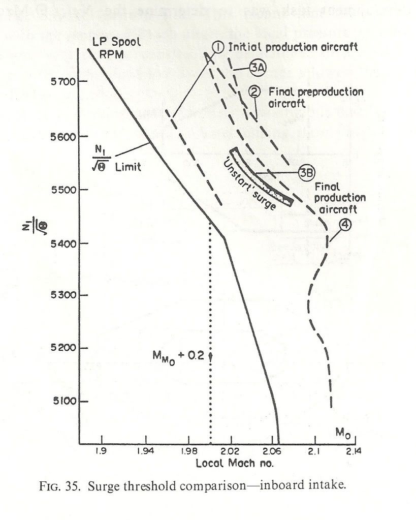
Here are a couple of diagrams to show what I mean. the first shows the surge lines for the various aircraft variants and also the N1 limiter Dude was talking about. NB: the X-axis is LOCAL Mach Number not freestream. The difference comes from the compression of the underwing flow by the bit of the wing ahead of the intake. Mmo + 0.2 is shown
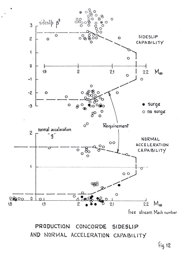
 ">The next shows the surge free boundaries in sideslip and normal acceleration. You can see the zero 'g' capability Dude was enthusing over.
 ">
">
As for 'high speed stall', I don't think we ever contemplated trying it! Our requirements in 'g' capability were defined and that was it. Besides, the aircraft would fly like the proverbial stone-built outbuilding at those sorts of conditions so I don't think one would have been able to get anywhere near a stall in the conventional sense. Stall as commonly defined for subsonics (deterrent buffet) might have been another matter, but I don't remember anything.
Cheers
Last edited by CliveL; 13th Jan 2011 at 11:17 . Reason: additional explanation
13th Jan 2011, 20:23
permalink Post: 1087
If you look at it from straight ahead it's not really a 'kink'.

From the angle the 'kinky' photo was taken the outer sweep of the ogee wing is towards the camera before sweeping aft to the drooped and washed-out tips and it looks like a kink in the LE sweep. The actual shape is seen better in the picture above. I've spent hours studying our G-BOAC at Manchester and to me the wing is a complex and lovely blend of curves and slopes, with no sudden changes such as a kink would require. Standing under the wing and observing it closely, no kink is apparent.
The wash-out on the tips shows particularly well in the above photo (washout is a forward twist of the wing at the tips to reduce the angle of attack of the tips compared to the rest of the wing, to prevent tip-stalling).
A question I have, relating to the photo above, is about the LE. The LE definately 'droops' in the area ahead of the intakes (it doesn't do so nearer the roots or tips). Is this to provoke a clean flow-breakaway in this area at high angles of attack to encourage the votices to form at this point as the wing transitions to vortex lift?
M2Dude Thanks for the kind words and careful explanations. I take it from your description of the anti-skid that once the mains start to rotate the brakes can be used, as the anti-skid comes 'off' (mains no longer think they are skidding).
I thought there was protection to prevent brake use until the nose wheels have landed, else brake application with the nose high would cause a rapid nose-down pitch, slamming the nosewheels on! Is there any such protection?
Last edited by Shaggy Sheep Driver; 13th Jan 2011 at 21:41 .
14th Jan 2011, 08:29
permalink Post: 1092
Quote:
| A question I have, relating to the photo above, is about the LE. The LE definately 'droops' in the area ahead of the intakes (it doesn't do so nearer the roots or tips). Is this to provoke a clean flow-breakaway in this area at high angles of attack to encourage the votices to form at this point as the wing transitions to vortex lift? |
The prototype had even more 'droop' in front of the intakes, but that produced a vortex at low incidence (near zero 'g') that went down the intakes and provoked surge.
Quote:
| The wash-out on the tips shows particularly well in the above photo (washout is a forward twist of the wing at the tips to reduce the angle of attack of the tips compared to the rest of the wing, to prevent tip-stalling). |
Cheers
Clive
PS: Everyone seems to be adding their favourite Concorde photograph so I thought I would be different and add my LEAST favourite
 ">
">
Last edited by CliveL; 14th Jan 2011 at 08:43 . Reason: adding a photo and additional remarks