3rd Apr 2011, 21:17
permalink Post: 1253
How many shockwaves does the concorde's inlet produce? I've been told it was like 3 or so, but looking at some diagrams it looks like there are 7... two stronger ones, three weaker ones, a bendy stronger one, a gap and then the terminal shock.
5th Apr 2011, 08:23
permalink Post: 1256
Jane-DoH
OK here we go:
1) The first shock was generated from the top lip of the intake
2) A second shock is generated from the fwd ramp hinge
3) A third isentropic fan shock is generated from the progressively
curved section of the fwd ramp
4) A 4th shock was generated fron the bottom lip
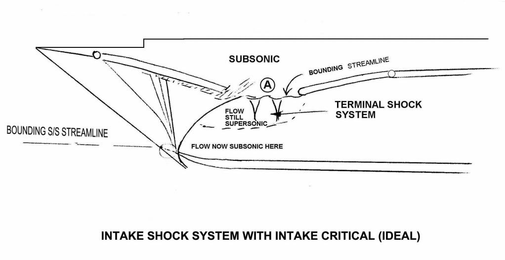
5) A terminal shock system is generated by the coalescence of
still supersonic and now subsonic air at the upper section of the ramp
area.
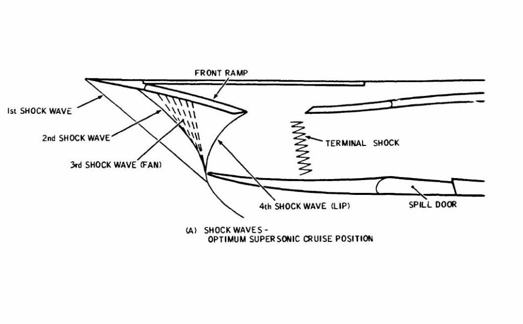
Hopefully these two diagrams will help. The first hand illustration above gives the 'theoretical' shock pattern and the second below gives an illustration of practical flows within the inlet. Both assume critical operation at Mach 2.
I hope all this blurb helps
Best regards
Dude
Quote:
| How many shockwaves does the concorde's inlet produce? I've been told it was like 3 or so, but looking at some diagrams it looks like there are 7... two stronger ones, three weaker ones, a bendy stronger one, a gap and then the terminal shock. |
1) The first shock was generated from the top lip of the intake
2) A second shock is generated from the fwd ramp hinge
3) A third isentropic fan shock is generated from the progressively
curved section of the fwd ramp
4) A 4th shock was generated fron the bottom lip
5) A terminal shock system is generated by the coalescence of
still supersonic and now subsonic air at the upper section of the ramp
area.
Hopefully these two diagrams will help. The first hand illustration above gives the 'theoretical' shock pattern and the second below gives an illustration of practical flows within the inlet. Both assume critical operation at Mach 2.
I hope all this blurb helps
Best regards
Dude
Last edited by M2dude; 5th Apr 2011 at 08:35 .
6th Apr 2011, 23:58
permalink Post: 1268
CliveL
Must have been a highly efficient inlet for a Mach 2 plane: Two traditional oblique waves; a fan-shock (also oblique); a shockwave off the lip that is normal and oblique depending on how far you are away from the lip, and a normal terminal shock.
So, isentropic would, in this context, mean that no shock-losses occurred at all?
Makes sense for an airliner that you would design an inlet this way
Quote:
| The first bit of the moveable front ramp was carefully shaped to give a sequence of weak shocks that reduced the Mach Number so gradually that shock losses were minimised. |
Quote:
| This was close to an isentropic process, hence the name. |
Quote:
| The whole point of the intake geometry was that the purely aerodynamic boundary between main duct and ramp void was infinitely flexible in shape, which made the design very tolerant of flow disturbances. |
7th Apr 2011, 11:16
permalink Post: 1270
Quote:
| Must have been a highly efficient inlet for a Mach 2 plane: Two traditional oblique waves; a fan-shock (also oblique); a shockwave off the lip that is normal and oblique depending on how far you are away from the lip, and a normal terminal shock. |
Quote:
| So, isentropic would, in this context, mean that no shock-losses occurred at all? |
8th Apr 2011, 01:00
permalink Post: 1277
Unique design.
Quote:
| I can think of no other design in the world, before or since, civil or military, where a supersonic engine/intake marriage gave such incredidable levels of performance, stability and predictability. |
Quote:
|
Without proper scheduling, disturbances inside the inlet could result
in the shock wave being expelled forward--a phenomenon known as an "inlet unstart." That causes an instantaneous loss of engine thrust, explosive banging noises and violent yawing of the aircraft--like being in a train wreck. Unstarts were not uncommon at that time in the SR-71's development, |
Basically, a relatively small failure within the intake/spike structure of the SR71 engine, was enough to simply tear the airframe apart within seconds of onset. The scale of forces within these structures therefore, must be almost beyond imagination and yet the Concorde design was such that she did not suffer such destructive failures.
My admiration for everyone who worked on her is endless.
8th Apr 2011, 03:42
permalink Post: 1279
M2Dude
Well, the XB-70 had an inlet with an efficiency in the 90% range but it wasn't as stable/predictable (it suffered unstarts).
911slf
What kind of vibration issue occurred?
Quote:
| I can think of no other design in the world, before or since, civil or military, where a supersonic engine/intake marriage gave such incredidable levels of performance, stability and predictability. |
911slf
Quote:
| I believe that engine #4 was limited to somewhat less than max power until 60kt because of a vibration issue. |
8th Apr 2011, 07:13
permalink Post: 1280
Jane-DoH
One of the real beauties of the Concorde intake was that it was completely self-startiing, and so unstarts as such were never heard of.
Regarding the vibrations thing, here is my post #80:
I seem to remember that Rolls Royce proposed a solution of their own, whre the right hand pair of engines would rotate ant-clockwise (viewed from the front) rather than the clockwise norm for just about any 'Roller' that I can think of. Although this would have completely solved the vibration problem, and was great business for the folks at RR in Patchway (just about doubling the required number of engines) it was a pretty lousy idea if you were an airline and required a much latger holding of spare engines.
One of the real beauties of the Concorde intake was that it was completely self-startiing, and so unstarts as such were never heard of.
Regarding the vibrations thing, here is my post #80:
Quote:
| The reason that #4 engine was limited to 88% N1 on take-off was an interesting one, down to something known as 'foldover effect'. This was discovered during pre-entry into service trials in 1975, when quite moderate levels of first stage LP compressor vibrations were experienced at take-off, but on #4 engine only. Investigations revealed that the vibrations were as the result of vorticies swirling into #4 intake, in an anti-clockwise direction, coming off the R/H wing leading edge. As the engine rotated clockwise (viewed from the front) these vorticies struck the blades edgewise, in the opposite DOR, thus setting up these vibrations. The vorticies were as a result of this 'foldover effect', where the drooping leading edge of the wing slightly shielded the streamtube flowing into the engine intake. #1 engine experienced identical vorticies, but this time, due to coming off of the L/H wing were in a clockwise direction, the same as the engine, so were of little consequence. It was found that by about 60 KTS the vorticies had diminished to the extent that the N1 limit could be automatically removed. Just reducing N1 on it's own was not really enough however; some of this distorted airflow also entered the air intake through the aux' inlet door (A free floating inward opening door that was set into the spill door at the floor of the intake. It was only aerodynamically operated). The only way of reducing this part of the problem was to mechanically limit the opening angle of the aux' inlet door, which left the intake slightly choked at take off power. (The aux' inlet door was purely aerodynamically operated, and diff' pressure completely it by Mach 0.93). |
12th Apr 2011, 05:47
permalink Post: 1295
Quote:
| Basically, a relatively small failure within the intake/spike structure of the SR71 engine, was enough to simply tear the airframe apart within seconds of onset. |
Quote:
|
Jim Zwayer, Lockheed flight-test specialist, and I were evaluating systems on an SR-71 Blackbird test from Edwards. We also were investigating procedures designed to reduce trim drag and improve high-Mach cruise performance. The latter involved flying with the center-of-gravity (CG) located further aft than normal, reducing the Blackbird's longitudinal stability.
On the planned test profile, we entered a programmed 35-deg. bank turn to the right. An immediate unstart occurred on the right engine, forcing the aircraft to roll further right and start to pitch up. I jammed the control stick as far left and forward as it would go. No response. I instantly knew we were in for a wild ride. The cumulative effects of system malfunctions, reduced longitudinal stability, increased angle-of-attack in the turn, supersonic speed, high altitude and other factors imposed forces on the airframe that exceeded flight control authority and the Stability Augmentation System's ability to restore control. The next day, our flight profile was duplicated on the SR-71 flight simulator at Beale AFB, Calif. The outcome was identical. Steps were immediately taken to prevent a recurrence of our accident. Testing at a CG aft of normal limits was discontinued, and trim-drag issues were subsequently resolved via aerodynamic means. The inlet control system was continuously improved and, with subsequent development of the Digital Automatic Flight and Inlet Control System, inlet unstarts became rare. |
9th Sep 2011, 19:27
permalink Post: 1450
Saw BOAG this weekend
I was in Seattle for a wedding this weekend, and got to see BOAG at the Museum of Flight.
It was gratifying, but I can't say she's in stellar condition. I'd give her a solid "B" grade. For one thing, it drives me nuts that all the literature and display placards all say "the Concorde." I far prefer Concorde to stand on her own. Her paint was dull and oxidized, and the exhibit sort of stands alone, without much in the way of history or surrounding material. It pained me a bit to see her outside in the Seattle weather, too. The interior is nice, being cordoned off by plexiglass that could stand a replacement sometime soon. I didn't see peeling paint.
That said, it was a spectacularly more enjoyable experience than the last time I saw Concorde F-BVFA at the Udvar Hazy museum in DC, thanks completely to this thread. I noticed things I'd never seen before, and took a much more profound appreciation of things like the curve and droop of the wing leading edge and the complexity of the engine intakes... and I loved seeing the difference in fuel consumption numbers between Concorde and the SR-71 also on display. My wife thinks I'm a genius because I knew why #4 engine was N1 limited below 60kt and what the little 3/4 tag to the left of the engine EGT gauges was for.
Thanks again to all the knowledgeable individuals on this thread.
24th Nov 2011, 05:21
permalink Post: 1492
CJ - AC does indeed have all 4 engines in place and complete. I wouldn't want to drop an engine as that would make her an incomplete aeroplane, and actually you can clearly see the compressors deep inside the intakes during tours, which is nice. She'd look odd with one intake blanked off.
Ideally I'd like a sectioned 593 on display, as there's not a lot to see on the outside of a turbojet engine except the ancilliaries - and you can see those by opening the engine bay doors.
Ideally I'd like a sectioned 593 on display, as there's not a lot to see on the outside of a turbojet engine except the ancilliaries - and you can see those by opening the engine bay doors.
5th Dec 2011, 14:32
permalink Post: 1507
Sorry to have caused some confusion....
BN2A is right : some of the pipes, pumps, generators, ancillariy gearboxes, connectors and suchlike on the outside of the 'round peg' are installed either on the left or the right side of the engine, so that they fit inside the 'square hole' while remaining accessible for inspection/maintenance.
911slf , all engines rotate in the same direction. However, the vortices rolling off the leading edges of the wings into the air intakes rotate in opposite directions.
Now if you look at a photo or a model, you'll see that the intakes of the outboard engines (#1 and #4) are quite close to the leading edges.
No problem for engine #1, because the rotation of the air entering the intake is the same as that of the engine itself, but for engine #4 there is a conflict between the senses of rotoation, leading to vibration at low speed.
Engine #3 is further back from the wing leading edge, so the airflow into the intake has already been 'straightened out' more, hence the problem doesn't occur there.
Maybe M2dude has some more details?
CJ
5th Dec 2011, 16:55
permalink Post: 1510
Christiaan,
To be honest, it was all a long time ago
#4 intake was marginally worse than #1 in several ways. Obviously this particular problem was linked to the engine face distortion pattern and may have been associated with the combination of the 'handedness' of the incoming vortex with the non-radial inlet guide vanes which together could have given some subtle variations in distortions between sides. But it was all pretty fine drawn stuff, and the problem disappeared by 60 kts or thereabouts.
CliveL
1st Feb 2012, 20:43
permalink Post: 1552
Quote:
| Two shock waves - the main one located on the nose, then an expansion field over the wing and a final shock at the tail where the flow was recompressed. [That is ignoring all the intake shocks!] The two compression shocks are what gives rise to the characteristic Boom-boom on the ground. |
Thanks.
Also, how was the flow re-compressed at the tail? What is the aerodynamic explanation of this?
As the intakes produced shocks, what about other protruberances such a aerials and drain masts etc? Did these also produce (small) shocks?
3rd Feb 2012, 18:31
permalink Post: 1555
Concorde shock waves
SSD: [quote]Thanks for this, CliveL. Could you please explain 'expansion field over the wing '?
Thanks.
Also, how was the flow re-compressed at the tail? What is the aerodynamic explanation of this?
As the intakes produced shocks, what about other protruberances such a aerials and drain masts etc? Did these also produce (small) shocks?[unquote]
I was generalising a bit and referring to the shocks as heard on the ground which take the form of a classic 'N' wave. This is a sudden rise in static pressure followed by a drop in static pressure to below atmospheric and then another sharp pressure rise. In supersonic flow any increase in static pressure is associated usually described as some sort of compression and conversely a drop in static pressure as an expansion. Since this happens over the region where the wing sits I described it as an expansion field over the wing.
The N wave is OK for the 'far field' shock characteristics, but as you hint, the flow near the aircraft is more complex than that - all the separate shocks gradually. merge into the bow and tail shocks. In the near field all the aerials, drain masts etc have their own little shock waves of course.
I have never seen a completely satisfactory explanation for the drop in static pressure, but if you will accept a much simplified description .....
I think there are two parts to the explanation.
The pressure over the upper wing surface will be below atmospheric static in the usual sense when lift is being generated - this will depend on the amount of lift (and hence weight)
Besides that there is a term related to the volume of the aircraft. One graphic description I have seen is that flying along at 2.0M the aircraft 'tears a hole' in the atmosphere that the surrounding air, being limited to 1.0M cannot fill. Consequently there is a drop in static pressure around the airframe. When the aircraft is past the 'void' is filled up and the resulting rapid increase in static pressure goes with the rearmost shock. This tail shock is sometimes described as the rarefaction shock.
This may not be scientifically accurate, but it satisfies me
CliveL
9th Jul 2012, 19:30
permalink Post: 1652
I have a query about the thrust of Concorde's engines. The quoted static thrust of the Olympus 593 is 32,000lb, but it has been frequently stated that in supercruise, the majority of the thrust was provided by the intakes. That being so, how much thrust was actually produced overall at Mach 2, and how was this measured (if indeed it ever was)?
4th Aug 2012, 11:43
permalink Post: 1663
Brian,
I don't think there is any published explanation, but maybe this will help.
Basically the problem with #4 intake was that it was on the RHS of the airplane. We are talking about low speed right? and especially zero forward speed when the engine is trying to suck as much air as it can get from wherever it can get it. That means that the induced angle of attack on all the intake leading edges is going to be high.
The best drawing I can find that shows the flow into the right hand pair is this
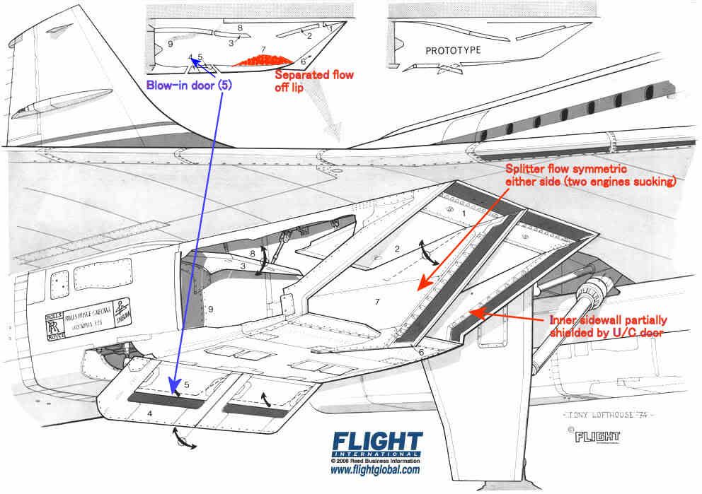
The intake leading edges were all sharp, so the flow would separate if subjected to a high AoA. The upper lip was protected a little by the wing leading edge, and we were obliged to modify the prototype LE ahead of the intakes to prevent underwing vortices developing at low AoA in cruise which also helped a bit.
The lower lip had a substantial separated flow 'bubble' at low forward speed as shown in red, but this cleared up quite quickly as the aircraft gathered speed. It was'cured' by the blow-in doors.
The inner sidewalls were shielded by the landing gear doors, so the AoAs on the sidewall on that side were quite modest.
The splitter was of course subject to equal flow demands on either side so the flow over that was pretty well symmetric.
That leaves the two outer sidewalls which, look for all the world like highly swept delta wings with sharp LEs mounted vertically.
Like all such wings when operated at high AoA they develop powerful vortices on the 'leeward' side. Looking back towards the engine the vortex on #4 engine was anticlockwise and that on #1 was clockwise. [Hope I got that one the right way round ]
]
The OL593 rotates clockwise looking aft so the induced incremental AoA on the compressor blades was different on #1 and #4. The difference was enough to trigger some mild blade vibration - hence the rpm restriction until the intake capture was good enough to reduce the vortex strength.
I don't think there is any published explanation, but maybe this will help.
Basically the problem with #4 intake was that it was on the RHS of the airplane. We are talking about low speed right? and especially zero forward speed when the engine is trying to suck as much air as it can get from wherever it can get it. That means that the induced angle of attack on all the intake leading edges is going to be high.
The best drawing I can find that shows the flow into the right hand pair is this
The intake leading edges were all sharp, so the flow would separate if subjected to a high AoA. The upper lip was protected a little by the wing leading edge, and we were obliged to modify the prototype LE ahead of the intakes to prevent underwing vortices developing at low AoA in cruise which also helped a bit.
The lower lip had a substantial separated flow 'bubble' at low forward speed as shown in red, but this cleared up quite quickly as the aircraft gathered speed. It was'cured' by the blow-in doors.
The inner sidewalls were shielded by the landing gear doors, so the AoAs on the sidewall on that side were quite modest.
The splitter was of course subject to equal flow demands on either side so the flow over that was pretty well symmetric.
That leaves the two outer sidewalls which, look for all the world like highly swept delta wings with sharp LEs mounted vertically.
Like all such wings when operated at high AoA they develop powerful vortices on the 'leeward' side. Looking back towards the engine the vortex on #4 engine was anticlockwise and that on #1 was clockwise. [Hope I got that one the right way round
]
The OL593 rotates clockwise looking aft so the induced incremental AoA on the compressor blades was different on #1 and #4. The difference was enough to trigger some mild blade vibration - hence the rpm restriction until the intake capture was good enough to reduce the vortex strength.
1st Sep 2012, 00:31
permalink Post: 1665
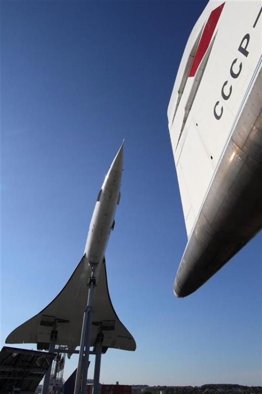
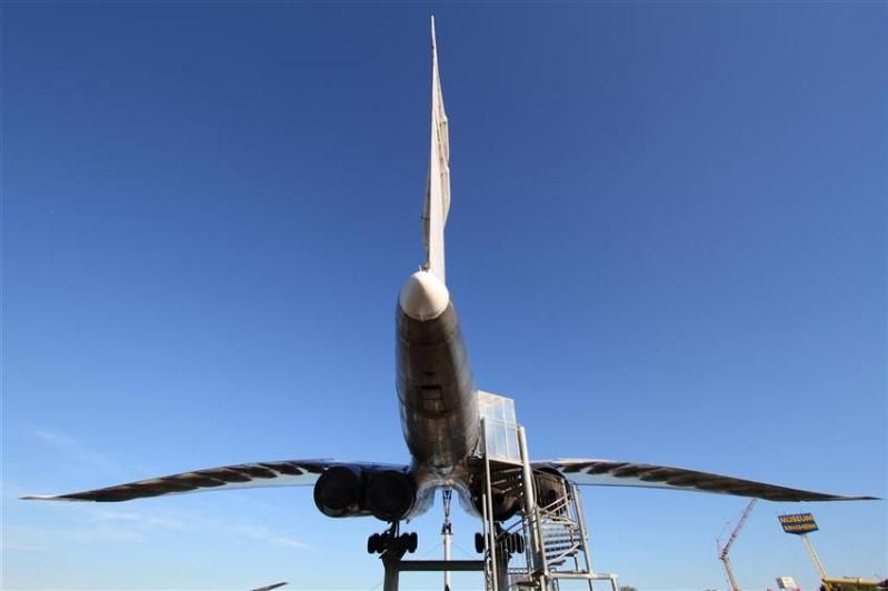
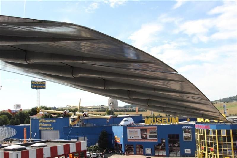
Concorde and TU-144 at Sinsheim
Earlier this week I had the great pleasure of a late afternoon followed by a full day at the Sinsheim technical museum near Heidelberg. Highly recommended and much more than just a museum; just ask my children what they thought of the helter-skelter from elevated Ilyushin IL-18 back down to the ground, or the twisting and turning stainless steel tubular slide from museum roof mounted DC3, through a hole in the roof, and back to the ground level entrance! The staff I encountered were all friendly and informed and I now look forwards to a day at the sister museum in Speyer - replete with 747-200 on the roof on which visitors can walk the wing.
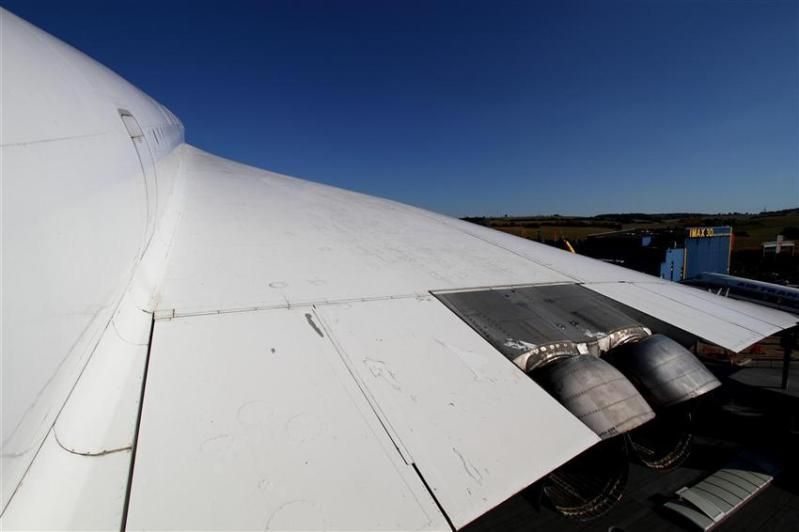
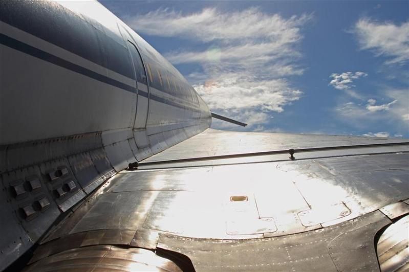
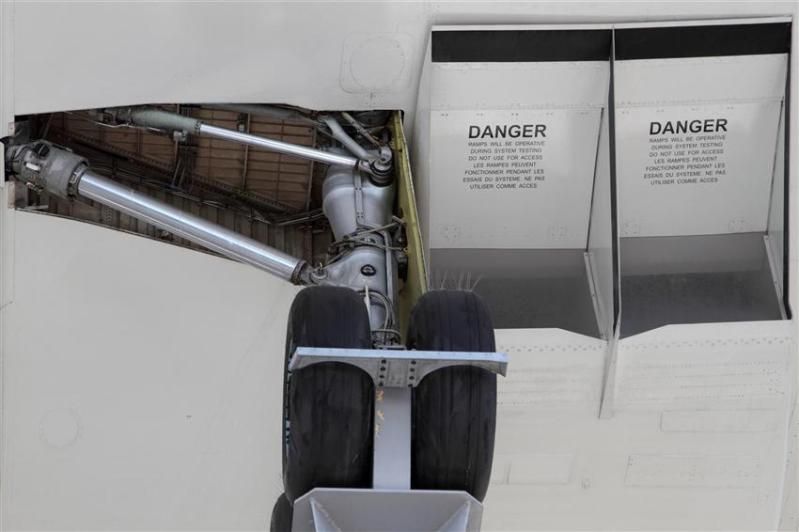
Anyway, of relevance to this thread I thought I'd shared some of my photos of Concorde F-BVFB and Tupolev TU-144 77112. It was tremendous to be able to walk backwards and forwards between the two, directly comparing design features and relative elegance of execution. Both are achievements for mankind but I have to say that to me not being an aeronautical engineer, Concorde won every time - dreary Air France cabin notwithstanding - with the larger Tupolev coming over as somewhat clumsy; let alone knowing engine technologies to be a world apart, just compare the wheel bogies as one example, and then the cleanliness of wing design as another. Yes, the Tupolev canards were a novel feature, but I understand they were only necessary in the first place because of lower speed control issues as a result of more basic aerodynamics.
Like any aircraft on static display exposed to the elements both airframes could do with some TLC, but here are the photos:
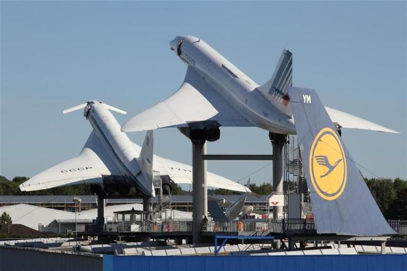
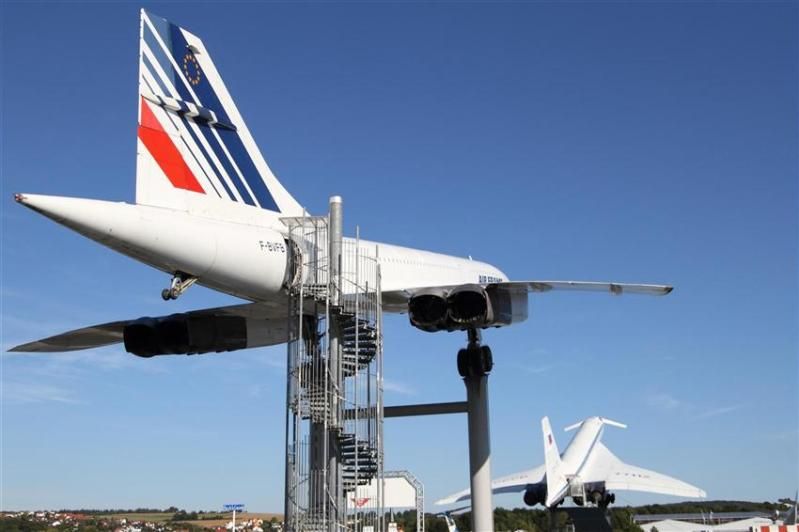
Concorde aft cabin door
TU-144 aft cabin door
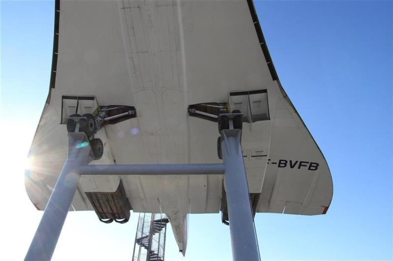
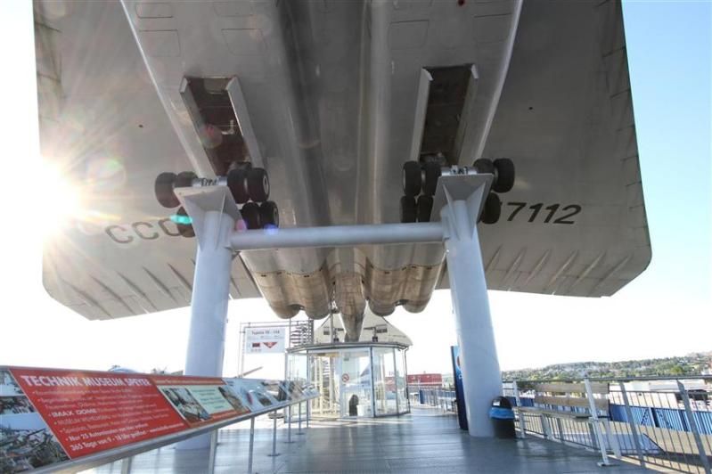
TU-144 No 4 engine location viewed from exhaust towards inlet (and directly in to the sun!)
To be continued in separate post as I have hit the photo count ceiling in this one.
Anyway, of relevance to this thread I thought I'd shared some of my photos of Concorde F-BVFB and Tupolev TU-144 77112. It was tremendous to be able to walk backwards and forwards between the two, directly comparing design features and relative elegance of execution. Both are achievements for mankind but I have to say that to me not being an aeronautical engineer, Concorde won every time - dreary Air France cabin notwithstanding - with the larger Tupolev coming over as somewhat clumsy; let alone knowing engine technologies to be a world apart, just compare the wheel bogies as one example, and then the cleanliness of wing design as another. Yes, the Tupolev canards were a novel feature, but I understand they were only necessary in the first place because of lower speed control issues as a result of more basic aerodynamics.
Like any aircraft on static display exposed to the elements both airframes could do with some TLC, but here are the photos:
Concorde aft cabin door
TU-144 aft cabin door
TU-144 No 4 engine location viewed from exhaust towards inlet (and directly in to the sun!)
To be continued in separate post as I have hit the photo count ceiling in this one.
28th Oct 2012, 08:16
permalink Post: 1691
@ peter kent
As you say, a complex subject!
Maybe the missing link is that a plane shock is not the only way to decelerate through Mach 1.0. If the nose of a body is blunt, or if the angle you are trying to turn the flow through is too big then the shock wave becomes detached from the leading edge of the body. The bit of the shock on the 'cusp' is then actually a very strong plane (normal) shock and the flow immediately behind that part is subsonic. In the case of a sharp surface with a large tuning angle this subsonic flow allows air to escape from the high pressure side of the surface to the low pressure side. This would be the case for example if the flow onto the leading edge of an intake hit it at too big an angle.
Supersonic intakes come in two basic guises - external compression and internal compression. The ramjet intakes you have been reading about are the latter type in which all the deceleration/compression takes place inside the intake. In these designs the final compression is through a normal shock situated at the minimum area 'throat' of the intake where the flow is close to Mach 1.0. This flow is delicately balanced and if some engine disturbance causes the shock to move into the converging supersonic bit of the intake the whole shock system can be expelled giving all sorts of problems (inlet unstart). Generally they are used for high Mach numbers where their higher theoretical efficiency and low external/spillage drag count for more than the additional control system complexity and performance requirements.
In external compression intakes (a simple pitot intake would be an extreme example), all the compression is done by a system of shock waves that sit outside the intake. These intakes are less efficient than internal compression intakes and they also spill a lot of air which produces external drag. Usually restricted to low supersonic Mach numbers.
Concorde's intake was a "mixed compression" design which had some features of each type. At low engine mass flow demands the flow coming on to the cowl lip could be at too great an angle to maintain attached shock waves so it behaved a bit like that described earlier. You can see this most clearly in the left hand picture where the lower efficiency and higher spillage can be seen in the graph of efficiency against intake capture (epsilon). In this state the intake behaved more like an external compression type and there was no appreciable final normal shock.
At high engine demand the angle of flow hitting the cowl was such that the shock waves remained attached and the intake functioned more like an internal compression design. Again you can see this in the right hand picture which shows most of the intake throat covered by a normal shock and in the graph where total intake flow (engine plus bleed) is constant.
On condition there was a bit of each, but since it was designed to minimise spillage you cannot see the detachment of the cowl lip shock at the scale of the diagram.
Hope this is helpful rather than additionally confusing!
PS: Looking at the centre picture again, it occurs to me that the curved shock running from the lip back and up to the reversed "D" would actually be normal to the approaching local flow which was being turned by the ramps and the isentropic compression. This would be the shock you are looking for to decelerate the flow to subsonic conditions. In other words the intake was functioning as an external compression design over this part.
Last edited by CliveL; 28th Oct 2012 at 08:28 .
8th May 2013, 16:05
permalink Post: 1714
For the french speaking (or reading) people here, I just found a mine of very interesting informations about Concorde on this website:
Accueil
This site has a database of thousand of concorde flights with the following datas: Date and time of the flight, airframe used, technical and commercial crews, guests, departure/arrival airports and flight type (regular, charter world tour...).
On top of that, many infos and stories around Concorde can also be found there.
I can't resist to translate one of those stories (I'm far from being a native english speaker or a professional translator; so forgive me for the misspellings and other translation mistakes). It is a report about one of the biggest incident that happened to the prototype 001 during the flight tests:
Shock of shockwaves
We were flying with Concorde at Mach 2 since 3 month already on both side of the Channel. The prototype 001 did outstrip 002 which was supposed to be the first to reach Mach 2.
Unfortunately, a technical issue delayed 002 and Brian Trubshaw fairly let Andr\xe9 Turcat be the first to reach Mach 2 with the 001 which was ready to go.
The flight tests were progressing fast and we were discovering a part of the atmosphere that military aircrafts hardly reached before. With Concorde, we were able to stay there for hours although limited by the huge fuel consumption of the prototypes.
The Olympus engines did not reached their nominal performance yet and, most of the time, we had to turn on the reheat in supersonic cruise to maintain Mach 2.
The reheat is what we call afterburner on military aircrafts. Fuel is injected between the last compressor stage of the low pressure turbine and the first exhaust nozzle. This increases the thrust for the whole engine and its nozzle.
The 4 reheats, one for each engine, are controlled by the piano switches behind the thrust leavers on the center pedestal between the two pilots. Air was fed into the engines through 4 air intakes, one for each engine, attached 2 by 2 to the 2 engine nacelle, one under each wing. The advantage in terms of drag reduction was obvious.
However, tests in wind tunnel showed that, at supersonic speed, if a problem happens on one engine, there was a great chance for the adjacent engine to be affected as well by the shockwave interference from one air intake to the other despite the presence the dividing wall between the two intakes. So we knew that an engine failure at mach 2 would result in the loss of 2 engines on the same side, resulting in a lateral movement leading to a strong sideslip that would likely impact the 2 remaining engines and transform the aircraft into the fastest glider in the world.
This is why an automatic anti sideslip device was developed and installed on the aircrafts.
The air intakes are very sophisticated. At mach 2, it creates a system of shockwaves that slows down the air from 600 m/sec in front of the aircraft to 200 m/sec in front of the engine while maintaining a very good thermodynamic performance. In supersonic cruise, the engines, operating at full capacity all the time, were sensitive to any perturbation and reacted violently with engine surge: the engine refusing the incoming air.
Stopping suddenly a flow of almost 200kg of air per second traveling at 600m/sec causes a few problems. As a result, a spill door was installed under the air intake and automatically opened in such event.
To control the system of shockwaves and obtain an efficiency of 0,96 in compression in the air intake, 2 articulated ramps, controlled by hydraulic jacks, are installed on the top of the air intakes in front of the engines. Each ramp is roughly the size of a big dining room table, and the 2 ramps, mechanically synchronized, move up or down following the instruction of an highly sophisticated computer that adapts the ramp position according to the mach number, the engine rating and other parameters such as skidding.
At that time, it was the less known part of the aircraft, almost only designed through calculation since no simulator, no wind tunnel, did allow a full scale test of the system.
The control of the system was analog and very complex but it was not easy to tune and we were moving ahead with a lot of caution in our test at mach 2.
On the 26th of January 1971, we were doing a nearly routine flight to measure the effect of a new engine setting supposed to enhance the engine efficiency at mach 2. It was a small increase of the rotation speed of the low pressure turbine increasing the air flow and, as a result, the thrust.
The flight test crews now regularly alternate their participation and their position in the cockpit for the pilots.
Today, Gilbert Defer is on the left side, myself on the right side, Michel R\xe9tif is the flight engineer, Claude Durand is the main flight engineer and Jean Conche is the engine flight engineer. With them is an official representative of the flight test centre, Hubert Guyonnet, seated in the cockpit's jump seat, he is in charge of radio testing.
We took off from Toulouse, accelerated to supersonic speed over the Atlantic near Arcachon continuing up to the north west of Ireland.
Two reheats, the 1 and the 3, are left on because the air temperature does not allow to maintain mach 2 without them.
Everything goes fine. During the previous flight, the crew experienced some strong turbulence, quite rare in the stratosphere and warned us about this. No problem was found on the aircraft.
We are on our way back to Toulouse off the coast of Ireland. Our program includes subsonic tests and we have to decelerate.
Gilbert is piloting the aircraft. Michel and the engineers notify us that everything is normal and ready for the deceleration and the descent.
We are at FL500 at mach 2 with an IAS of 530 kt, the maximum dynamic pressure in normal use.
On Concorde, the right hand seat is the place offering the less possibility to operate the systems. But here, we get busy by helping the others to follow the program and the checklists and by manipulating the secondary commands such as the landing gear, the droop nose, the radio navigation, comms, and some essential engine settings apart from the thrust leavers such as the reheat switches.
The normal procedure consists in stopping the reheat before lowering the throttle.
Gilbert asks me to do it. After, he will slowly reduce the throttle to avoid temporary heckler. Note that he did advise us during the training on the air intake to avoid to move the thrust leaver in case of engine surge.
As a safety measure, I shut down the reheat one by one, checking that everything goes fine for each one. Thus I switch off the reheat 1 with the light shock marking the thrust reduction. Then the 3\x85
Instantly, we are thrown in a crazy situation.
Deafening noise like a canon firing 300 times a minute next to us. Terrible shake. The cockpit, that looked like a submarine with the metallic and totally opaque visor obviously in the upper position, is shaken at a frequency of 5 oscillation a second and a crazy amplitude of about 4 to 5 G. To the point that we cannot see anymore, our eyes not being able to follow the movements.
Gilbert has a test pilot reaction, we have to get out of the maximum kinetic energy zone as fast as possible and to reduce speed immediately. He then moves the throttle to idle without any useless care.
During that time, I try, we all try to answer the question: what is going on? What is the cause of this and what can we do to stop it?
Suspecting an issue with the engines, I try to read the indicators on the centre control panel through the mist of my disturbed vision and in the middle of a rain of electric indicators falling from the roof. We cannot speak to each other through the intercom.
I vaguely see that the engines 3 and 4 seem to run slower than the 2 others, especially the 4. We have to do something. Gilbert is piloting the plane and is already busy. I have a stupid reaction dictated by the idea that I have to do something to stop that, while I can only reach a few commands that may be linked to the problem.
I first try to increase the thrust on number 4 engine. No effect so I reduce frankly and definitively. I desperately look for something to do from my right hand seat with a terrible feeling of being helpless and useless.
Then everything stops as suddenly as it started. How long did it last, 30 seconds, one minute?
By looking at the flight data records afterward, we saw that it only last\x85 12 seconds!
However, I have the feeling that I had time to think about tons of things, to do a lot of reasoning, assumption and to have searched and searched and searched\x85! It looked like my brain suddenly switched to a fastest mod of thinking. But, above all, it's the feeling of failure, the fact that I was not able to do anything and that I did not understand anything that remains stuck in my mind forever.
To comfort me, I have to say that nobody among the crew did understand anything either and was able to do anything, apart from Gilbert.
The aircraft slows down and the engine 3 that seemed to have shut down restart thanks to the auto ignition system. But the 4 is off indeed.
Michel makes a check of his instruments. He also notes that the engine 4 has shut down but the 4 air intakes work normally, which makes us feel better. After discussing together, we start to think that we probably faced some stratospheric turbulence of very high intensity, our experience in this altitude range being quite limited at that time. But nobody really believes in this explanation. Finally, at subsonic speed, mach 0.9, with all instruments looking normal, we try to restart engine 4 since we still have a long way to go to fly back to Toulouse.
Michel launches the process to restart the engine. It restarts, remains at a medium rotation speed and shuts down after 20 seconds, leaving us puzzled and a bit worried despite the fact that the instrument indicators are normal.
Gilbert then decide to give up and won't try to restart this engine anymore and Claude leaves his engineer station to have a look in a device installed on the prototype to inspect the landing gear and the engines when needed: an hypo-scope, a kind of periscope going out through the floor and not through the roof.
After a few seconds, we can hear him on the intercom:
"Shit! (stuttering) we have lost the intake number 4."
He then describes a wide opening in the air intake, the ramp seems to be missing and he can see some structural damages on the nacelle.
Gilbert reacts rapidly by further reducing the speed to limit even more the dynamic pressure.
But we don't know exactly the extent of the damage. Are the wing and the control surfaces damaged? What about engine 3?
We decide to fly back at a speed of 250 kts at a lower altitude and to divert toward Fairford where our british colleagues and the 002 are based. I inform everybody about the problem on the radio and tell them our intentions. However, I add that if no other problems occur, we will try to reach Toulouse since we still have enough fuel.
Flying off Fairford, since nothing unusual happened, we decide to go on toward Toulouse. All the possible diversion airport on the way have been informed by the flight test centre who follows us on their radar.
At low speed, knowing what happened to us and having nothing else to do but to wait for us, time passes slowly, very slowly and we don't talk much, each one of us thinking and trying to understand what happened. However, we keep watching closely after engine 3.
Personally, I remember the funny story of the poor guy who sees his house collapse when he flushes his toilets. I feel in the same situation.
Gilbert makes a precautionary landing since we don't rely much on engine 3 anymore. But everything goes fine.
At the parking, there is a lot of people waiting for us and, as soon as the engines stop, we can see a big rush toward the nacelles of the right hand side engines.
Gilbert and myself are the first to get off the plane and we are welcomed down the stairs by Andr\xe9 Turcat and Jean Franchi who came out from the crowd watching at the right hand side nacelle.
They both behave the same way, with a slow pace attitude, the same look, a mix of disbelief and frustration.
Andr\xe9 is the first to speak: "I can't believe we were not on this flight, really unlucky\x85". Yes, this flight was supposed to be just a routine flight\x85!
The condition of the nacelle is impressive. We come closer and everybody move aside for us with a look of disbelief and respect as if we were hell survivors.
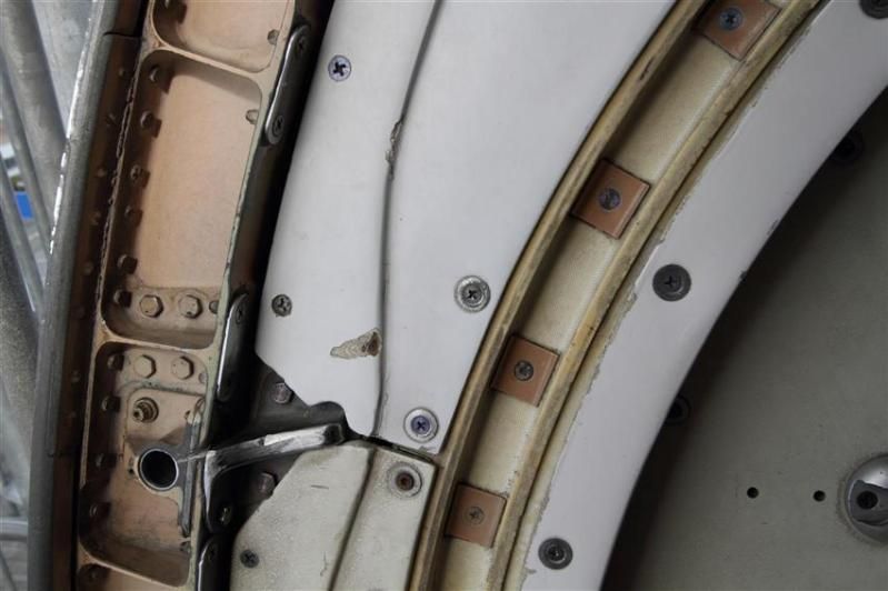
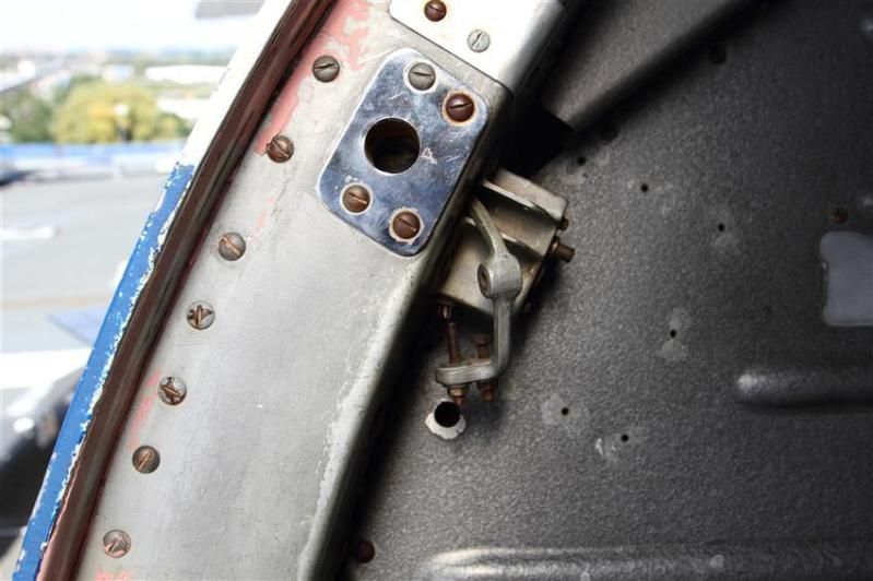
The ramps of the intake 4, those 2 "dining tables", have completely disappeared leaving a hole where we can see the hydraulic jacks and the stub rod where the ramps were attached.
Indeed, only the ramps were missing, apparently ejected forward which was unbelievable knowing how fast we were flying. The ramp slipped under the nacelle causing some damages on it and on the hood of one of the elevon's servo control. Fortunately, the control did not suffer any damage.
What is left of the rear ramp seems to be blocked down inside the intake in front of the engine and we can see behind it the first blades of the compressor, or what is left of it, not much.
The engine swallowed a huge amount of metal but no vital parts of the aircraft has been damaged, no hydraulic leaks, no fuel leaks. I remembered at that time the stories of some B58 Hustler accident where the loss of an engine at mach 2 almost certainly ended with the complete loss of the aircraft. Our Concorde has only been shaken. This incident strengthened the trust I had in this plane. And I was not unhappy to have experienced this ordeal, especially when I saw the frustration on the face of Andr\xe9 Turcat and Jean Franchi.
But we had to understand what happened and how; and also why the ramp's fixing broke.
It didn't take much time to get the answers.
I unintentionally triggered the problem when shutting down the reheat of engine 3. The sudden stop of the fuel flow did of course stop the combustion and the back pressure behind the low pressure turbine. But, probably because of the modification made on the engine before the flight, the stop of the reheat has not been followed by the normal closing movement of the primary nozzle to compensate the pressure drop. So the low pressure turbine ran out of control, dragging down the low pressure compressor which reacts by surging.
Despite the opening of the spill door, the engine surge led to a sudden movement of the shockwaves in the air intake creating a surge in the intake itself. A similar surge happened in the adjacent intake 4 followed by a surge of the corresponding engine. This caused an excessive pressure above the ramps and the fixings of the intake 4 did not hold.
Since it was the first time we experienced a surge in the air intake, we had little knowledge of the stress it would create on the ramps. This led to miscalculation of the strength of the ramps's frames and they did brake.
Another mistake: instead of installing the motion detectors on the ramp itself, to make the production easier, they have been placed on the arms of the hydraulic jacks. This is why Michel R\xe9tif thought that the position of the ramps were correct. The hydraulic jacks did not suffer any damage and were still working normally even if the ramps were missing.
All the data recorded during this event helped us in redesigning the air intakes and the flight test program resumed three month later.
After this, we deliberately created dozen and dozen of air intake surge to fine tune the way to regulate them with digital calculator this time.
From now on, even if it was still very impressive, it was safe and their intensity was not comparable with what we experienced with the missing ramps.
However, a french president may kept a lasting memory of this, much later, during a flight back from Saudi Arabia. This time, I was on the left side, Gilbert on the right and Michel was still in the third seat\x85 But that's another story.
For me, the lasting impression of failing and being helpless during this incident made me wonder what a commercial pilot would have done in this situation. This plane was designed to be handled by standard commercial pilots and not only by the flight test pilots.
At that time, I was interested in taking in charge the management of a training center for the pilots of the future Airbus's clients. This event pushed me that way and I made it clear that I wanted to add the flight training on Concorde in this project. This has been agreed and I did it.
And the Concorde training program now covers the air intake surges and how to deal with them.
Jean PINET
Former test pilot
Member and former president of the Air and Space Academy
Accueil
This site has a database of thousand of concorde flights with the following datas: Date and time of the flight, airframe used, technical and commercial crews, guests, departure/arrival airports and flight type (regular, charter world tour...).
On top of that, many infos and stories around Concorde can also be found there.
I can't resist to translate one of those stories (I'm far from being a native english speaker or a professional translator; so forgive me for the misspellings and other translation mistakes). It is a report about one of the biggest incident that happened to the prototype 001 during the flight tests:
Shock of shockwaves
We were flying with Concorde at Mach 2 since 3 month already on both side of the Channel. The prototype 001 did outstrip 002 which was supposed to be the first to reach Mach 2.
Unfortunately, a technical issue delayed 002 and Brian Trubshaw fairly let Andr\xe9 Turcat be the first to reach Mach 2 with the 001 which was ready to go.
The flight tests were progressing fast and we were discovering a part of the atmosphere that military aircrafts hardly reached before. With Concorde, we were able to stay there for hours although limited by the huge fuel consumption of the prototypes.
The Olympus engines did not reached their nominal performance yet and, most of the time, we had to turn on the reheat in supersonic cruise to maintain Mach 2.
The reheat is what we call afterburner on military aircrafts. Fuel is injected between the last compressor stage of the low pressure turbine and the first exhaust nozzle. This increases the thrust for the whole engine and its nozzle.
The 4 reheats, one for each engine, are controlled by the piano switches behind the thrust leavers on the center pedestal between the two pilots. Air was fed into the engines through 4 air intakes, one for each engine, attached 2 by 2 to the 2 engine nacelle, one under each wing. The advantage in terms of drag reduction was obvious.
However, tests in wind tunnel showed that, at supersonic speed, if a problem happens on one engine, there was a great chance for the adjacent engine to be affected as well by the shockwave interference from one air intake to the other despite the presence the dividing wall between the two intakes. So we knew that an engine failure at mach 2 would result in the loss of 2 engines on the same side, resulting in a lateral movement leading to a strong sideslip that would likely impact the 2 remaining engines and transform the aircraft into the fastest glider in the world.
This is why an automatic anti sideslip device was developed and installed on the aircrafts.
The air intakes are very sophisticated. At mach 2, it creates a system of shockwaves that slows down the air from 600 m/sec in front of the aircraft to 200 m/sec in front of the engine while maintaining a very good thermodynamic performance. In supersonic cruise, the engines, operating at full capacity all the time, were sensitive to any perturbation and reacted violently with engine surge: the engine refusing the incoming air.
Stopping suddenly a flow of almost 200kg of air per second traveling at 600m/sec causes a few problems. As a result, a spill door was installed under the air intake and automatically opened in such event.
To control the system of shockwaves and obtain an efficiency of 0,96 in compression in the air intake, 2 articulated ramps, controlled by hydraulic jacks, are installed on the top of the air intakes in front of the engines. Each ramp is roughly the size of a big dining room table, and the 2 ramps, mechanically synchronized, move up or down following the instruction of an highly sophisticated computer that adapts the ramp position according to the mach number, the engine rating and other parameters such as skidding.
At that time, it was the less known part of the aircraft, almost only designed through calculation since no simulator, no wind tunnel, did allow a full scale test of the system.
The control of the system was analog and very complex but it was not easy to tune and we were moving ahead with a lot of caution in our test at mach 2.
On the 26th of January 1971, we were doing a nearly routine flight to measure the effect of a new engine setting supposed to enhance the engine efficiency at mach 2. It was a small increase of the rotation speed of the low pressure turbine increasing the air flow and, as a result, the thrust.
The flight test crews now regularly alternate their participation and their position in the cockpit for the pilots.
Today, Gilbert Defer is on the left side, myself on the right side, Michel R\xe9tif is the flight engineer, Claude Durand is the main flight engineer and Jean Conche is the engine flight engineer. With them is an official representative of the flight test centre, Hubert Guyonnet, seated in the cockpit's jump seat, he is in charge of radio testing.
We took off from Toulouse, accelerated to supersonic speed over the Atlantic near Arcachon continuing up to the north west of Ireland.
Two reheats, the 1 and the 3, are left on because the air temperature does not allow to maintain mach 2 without them.
Everything goes fine. During the previous flight, the crew experienced some strong turbulence, quite rare in the stratosphere and warned us about this. No problem was found on the aircraft.
We are on our way back to Toulouse off the coast of Ireland. Our program includes subsonic tests and we have to decelerate.
Gilbert is piloting the aircraft. Michel and the engineers notify us that everything is normal and ready for the deceleration and the descent.
We are at FL500 at mach 2 with an IAS of 530 kt, the maximum dynamic pressure in normal use.
On Concorde, the right hand seat is the place offering the less possibility to operate the systems. But here, we get busy by helping the others to follow the program and the checklists and by manipulating the secondary commands such as the landing gear, the droop nose, the radio navigation, comms, and some essential engine settings apart from the thrust leavers such as the reheat switches.
The normal procedure consists in stopping the reheat before lowering the throttle.
Gilbert asks me to do it. After, he will slowly reduce the throttle to avoid temporary heckler. Note that he did advise us during the training on the air intake to avoid to move the thrust leaver in case of engine surge.
As a safety measure, I shut down the reheat one by one, checking that everything goes fine for each one. Thus I switch off the reheat 1 with the light shock marking the thrust reduction. Then the 3\x85
Instantly, we are thrown in a crazy situation.
Deafening noise like a canon firing 300 times a minute next to us. Terrible shake. The cockpit, that looked like a submarine with the metallic and totally opaque visor obviously in the upper position, is shaken at a frequency of 5 oscillation a second and a crazy amplitude of about 4 to 5 G. To the point that we cannot see anymore, our eyes not being able to follow the movements.
Gilbert has a test pilot reaction, we have to get out of the maximum kinetic energy zone as fast as possible and to reduce speed immediately. He then moves the throttle to idle without any useless care.
During that time, I try, we all try to answer the question: what is going on? What is the cause of this and what can we do to stop it?
Suspecting an issue with the engines, I try to read the indicators on the centre control panel through the mist of my disturbed vision and in the middle of a rain of electric indicators falling from the roof. We cannot speak to each other through the intercom.
I vaguely see that the engines 3 and 4 seem to run slower than the 2 others, especially the 4. We have to do something. Gilbert is piloting the plane and is already busy. I have a stupid reaction dictated by the idea that I have to do something to stop that, while I can only reach a few commands that may be linked to the problem.
I first try to increase the thrust on number 4 engine. No effect so I reduce frankly and definitively. I desperately look for something to do from my right hand seat with a terrible feeling of being helpless and useless.
Then everything stops as suddenly as it started. How long did it last, 30 seconds, one minute?
By looking at the flight data records afterward, we saw that it only last\x85 12 seconds!
However, I have the feeling that I had time to think about tons of things, to do a lot of reasoning, assumption and to have searched and searched and searched\x85! It looked like my brain suddenly switched to a fastest mod of thinking. But, above all, it's the feeling of failure, the fact that I was not able to do anything and that I did not understand anything that remains stuck in my mind forever.
To comfort me, I have to say that nobody among the crew did understand anything either and was able to do anything, apart from Gilbert.
The aircraft slows down and the engine 3 that seemed to have shut down restart thanks to the auto ignition system. But the 4 is off indeed.
Michel makes a check of his instruments. He also notes that the engine 4 has shut down but the 4 air intakes work normally, which makes us feel better. After discussing together, we start to think that we probably faced some stratospheric turbulence of very high intensity, our experience in this altitude range being quite limited at that time. But nobody really believes in this explanation. Finally, at subsonic speed, mach 0.9, with all instruments looking normal, we try to restart engine 4 since we still have a long way to go to fly back to Toulouse.
Michel launches the process to restart the engine. It restarts, remains at a medium rotation speed and shuts down after 20 seconds, leaving us puzzled and a bit worried despite the fact that the instrument indicators are normal.
Gilbert then decide to give up and won't try to restart this engine anymore and Claude leaves his engineer station to have a look in a device installed on the prototype to inspect the landing gear and the engines when needed: an hypo-scope, a kind of periscope going out through the floor and not through the roof.
After a few seconds, we can hear him on the intercom:
"Shit! (stuttering) we have lost the intake number 4."
He then describes a wide opening in the air intake, the ramp seems to be missing and he can see some structural damages on the nacelle.
Gilbert reacts rapidly by further reducing the speed to limit even more the dynamic pressure.
But we don't know exactly the extent of the damage. Are the wing and the control surfaces damaged? What about engine 3?
We decide to fly back at a speed of 250 kts at a lower altitude and to divert toward Fairford where our british colleagues and the 002 are based. I inform everybody about the problem on the radio and tell them our intentions. However, I add that if no other problems occur, we will try to reach Toulouse since we still have enough fuel.
Flying off Fairford, since nothing unusual happened, we decide to go on toward Toulouse. All the possible diversion airport on the way have been informed by the flight test centre who follows us on their radar.
At low speed, knowing what happened to us and having nothing else to do but to wait for us, time passes slowly, very slowly and we don't talk much, each one of us thinking and trying to understand what happened. However, we keep watching closely after engine 3.
Personally, I remember the funny story of the poor guy who sees his house collapse when he flushes his toilets. I feel in the same situation.
Gilbert makes a precautionary landing since we don't rely much on engine 3 anymore. But everything goes fine.
At the parking, there is a lot of people waiting for us and, as soon as the engines stop, we can see a big rush toward the nacelles of the right hand side engines.
Gilbert and myself are the first to get off the plane and we are welcomed down the stairs by Andr\xe9 Turcat and Jean Franchi who came out from the crowd watching at the right hand side nacelle.
They both behave the same way, with a slow pace attitude, the same look, a mix of disbelief and frustration.
Andr\xe9 is the first to speak: "I can't believe we were not on this flight, really unlucky\x85". Yes, this flight was supposed to be just a routine flight\x85!
The condition of the nacelle is impressive. We come closer and everybody move aside for us with a look of disbelief and respect as if we were hell survivors.
The ramps of the intake 4, those 2 "dining tables", have completely disappeared leaving a hole where we can see the hydraulic jacks and the stub rod where the ramps were attached.
Indeed, only the ramps were missing, apparently ejected forward which was unbelievable knowing how fast we were flying. The ramp slipped under the nacelle causing some damages on it and on the hood of one of the elevon's servo control. Fortunately, the control did not suffer any damage.
What is left of the rear ramp seems to be blocked down inside the intake in front of the engine and we can see behind it the first blades of the compressor, or what is left of it, not much.
The engine swallowed a huge amount of metal but no vital parts of the aircraft has been damaged, no hydraulic leaks, no fuel leaks. I remembered at that time the stories of some B58 Hustler accident where the loss of an engine at mach 2 almost certainly ended with the complete loss of the aircraft. Our Concorde has only been shaken. This incident strengthened the trust I had in this plane. And I was not unhappy to have experienced this ordeal, especially when I saw the frustration on the face of Andr\xe9 Turcat and Jean Franchi.
But we had to understand what happened and how; and also why the ramp's fixing broke.
It didn't take much time to get the answers.
I unintentionally triggered the problem when shutting down the reheat of engine 3. The sudden stop of the fuel flow did of course stop the combustion and the back pressure behind the low pressure turbine. But, probably because of the modification made on the engine before the flight, the stop of the reheat has not been followed by the normal closing movement of the primary nozzle to compensate the pressure drop. So the low pressure turbine ran out of control, dragging down the low pressure compressor which reacts by surging.
Despite the opening of the spill door, the engine surge led to a sudden movement of the shockwaves in the air intake creating a surge in the intake itself. A similar surge happened in the adjacent intake 4 followed by a surge of the corresponding engine. This caused an excessive pressure above the ramps and the fixings of the intake 4 did not hold.
Since it was the first time we experienced a surge in the air intake, we had little knowledge of the stress it would create on the ramps. This led to miscalculation of the strength of the ramps's frames and they did brake.
Another mistake: instead of installing the motion detectors on the ramp itself, to make the production easier, they have been placed on the arms of the hydraulic jacks. This is why Michel R\xe9tif thought that the position of the ramps were correct. The hydraulic jacks did not suffer any damage and were still working normally even if the ramps were missing.
All the data recorded during this event helped us in redesigning the air intakes and the flight test program resumed three month later.
After this, we deliberately created dozen and dozen of air intake surge to fine tune the way to regulate them with digital calculator this time.
From now on, even if it was still very impressive, it was safe and their intensity was not comparable with what we experienced with the missing ramps.
However, a french president may kept a lasting memory of this, much later, during a flight back from Saudi Arabia. This time, I was on the left side, Gilbert on the right and Michel was still in the third seat\x85 But that's another story.
For me, the lasting impression of failing and being helpless during this incident made me wonder what a commercial pilot would have done in this situation. This plane was designed to be handled by standard commercial pilots and not only by the flight test pilots.
At that time, I was interested in taking in charge the management of a training center for the pilots of the future Airbus's clients. This event pushed me that way and I made it clear that I wanted to add the flight training on Concorde in this project. This has been agreed and I did it.
And the Concorde training program now covers the air intake surges and how to deal with them.
Jean PINET
Former test pilot
Member and former president of the Air and Space Academy
Last edited by NHerby; 9th May 2013 at 17:24 .
18th Oct 2013, 21:59
permalink Post: 1736
BA was able to make money on Concorde as in positive cash flow. But they were basically given the airplanes. The commercial failure aspect comes from the simple fact that no one wanted them to build any more (what I've heard is that at least one production Concorde was built but never put into service - basically becoming a donor for spares - not sure if that's true). I also suspect it was too much of a point design - it didn't have the range to be useful in the Pacific.
If BA (and Air France) honestly thought Concorde was a profit center (rather than brand prestige), they would have wanted more .
.
BTW, my comments about the flight deck were not intended as criticism - no doubt it was state of the art when it was designed. I was just commenting on how much things have changed since then.
I don't mean to dispute that the Concorde was an incredible airplane and engineering achievement. Just saying that it never really had a chance to be successful. The same thing would have applied to the Boeing SST if it hadn't been cancelled (I knew a guy that worked on the Boeing SST inlet control system - talk about complex ). Cancelling the SST is probably the best thing that ever happened to Boeing - it likely would have bankrupted the company.

If BA (and Air France) honestly thought Concorde was a profit center (rather than brand prestige), they would have wanted more
.
BTW, my comments about the flight deck were not intended as criticism - no doubt it was state of the art when it was designed. I was just commenting on how much things have changed since then.
I don't mean to dispute that the Concorde was an incredible airplane and engineering achievement. Just saying that it never really had a chance to be successful. The same thing would have applied to the Boeing SST if it hadn't been cancelled (I knew a guy that worked on the Boeing SST inlet control system - talk about complex
). Cancelling the SST is probably the best thing that ever happened to Boeing - it likely would have bankrupted the company.
Last edited by tdracer; 18th Oct 2013 at 22:01 .