28th Oct 2010, 15:26
permalink Post: 623
Volume
,
Here are the drawings that should help with your last photo of Concorde "0001".
Not very good quality, since they're scans of xerox copies of xerox copies of microfilm ...
Prototype drawing dated July 1965, which in particular shows the location of the emergency exits.
Production drawing (two cut-outs from the same drawing at the same scale) which (schematically) does actually show the 'sloped areas' both at the front and the rear of the main landing gear bay.
Note 1 : both frame 54 and frame 60 were 'production breaks'.
Note 2 : the tanks were numbered differently on the prototypes ; tank N\xb0 9 on the prototype became tank n\xb0 6 on the production aircraft.
CJ
30th Oct 2010, 12:46
permalink Post: 642
Fuel Saving Landing
Requirements :
Not permitted with :
Notes
3-engine landings were permitted. For all landings the landing gear would be lowered earlier than normal to ensure the brakes were stone cold to start with, maximum reverse thrust would be used on landing, and braking modulated so as to use (nearly) all of the full length of the runway. Landing performance figures at 130,000 kgs were in the performance manual for most runways. Any runway for which this procedure had not been pre-authorised required some rather tedious calculations, using the generalised basic data and graphs found in the performance manual.
If manual performance calculations were necessary, the F/E and I usually seemed to find that another problem that required our urgent and undivided attention had come up, and we would reluctantly be compelled to hand over all the manuals, charts and graphs for the F/O to perform the calculations!
If the aircraft had an AFT ZFW CG (perhaps loaded with a lot of heavy bags in the rear hold), and given the specific fuel distribution requirements for a fuel saving landing, it was possible that the landing weight might have to be reduced below 130,000 kgs, in order to achieve a landing CG of 53.5%.
After landing, record the actual landing weight in the Maintenance Log using code 2899XXOO, sign it, and then leg it swiftly, to avoid M2Dude and the boys, who somehow always managed to imply that you were responsible for anything that had gone wrong with their pride and joy since they last handed her over to you!
Reasons
The clue is in the name! A possible saving of roughly 5,200 gallons of fuel, nearly 19,000 kgs, which need not be jettisoned, thus reducing the time spent in the air before re-landing, fuel costs and pollution.
Best Regards
Bellerophon
Requirements :
- Manual landing, at V REF , only
- Minimum of one autothrottle operative at start of approach
- Contingency power available
- Specific fuel distribution achieved
- Record in Maintenance Log
Not permitted with :
- Slippery runway
- Precipitation covered runway
- 3-engine ferry
- 2-engine approach and landing
- Reduced noise approach
- Fuelled with wide-cut fuel
- Secondary nozzle locked out
- Brake unit isolated
- Total loss of Electric Trim
- Total loss of Pitch Stab
- Total loss of Electrical Signalling
- Suspected tyre failure
Notes
3-engine landings were permitted. For all landings the landing gear would be lowered earlier than normal to ensure the brakes were stone cold to start with, maximum reverse thrust would be used on landing, and braking modulated so as to use (nearly) all of the full length of the runway. Landing performance figures at 130,000 kgs were in the performance manual for most runways. Any runway for which this procedure had not been pre-authorised required some rather tedious calculations, using the generalised basic data and graphs found in the performance manual.
If manual performance calculations were necessary, the F/E and I usually seemed to find that another problem that required our urgent and undivided attention had come up, and we would reluctantly be compelled to hand over all the manuals, charts and graphs for the F/O to perform the calculations!
If the aircraft had an AFT ZFW CG (perhaps loaded with a lot of heavy bags in the rear hold), and given the specific fuel distribution requirements for a fuel saving landing, it was possible that the landing weight might have to be reduced below 130,000 kgs, in order to achieve a landing CG of 53.5%.
After landing, record the actual landing weight in the Maintenance Log using code 2899XXOO, sign it, and then leg it swiftly, to avoid M2Dude and the boys, who somehow always managed to imply that you were responsible for anything that had gone wrong with their pride and joy since they last handed her over to you!
Reasons
The clue is in the name! A possible saving of roughly 5,200 gallons of fuel, nearly 19,000 kgs, which need not be jettisoned, thus reducing the time spent in the air before re-landing, fuel costs and pollution.
Best Regards
Bellerophon
21st Dec 2010, 18:09
permalink Post: 929
quote
 uring landing, Concorde isn't flared at all, it is flown onto the ground at a constant pitch attitude.
What does happen is that the ground effect over the last 50 ft or so of height considerably flattens the trajectory, so you do not touch down with the same vertical speed as during the final approach !
What also happens is that the ground effect produces a pitch-up moment, so the pilot has to push forward on the stick to maintain the same pitch attitude.
Putting the nosewheel down after touchdown is enough to completely \x93ruin\x94 the lift, so that there is no need for \x93lift-dumpers\x94 or spoilers.unquote
Sorry Christan, but I did the original pre first flight work on this one, so I know you are mistaken here. You are abolutely correct in saying that the ground effect cushions the aircraft beautifully so that all the pilot needs to do is to hold constant attitude, but the ground effect also produces a nose DOWN moment, so the pilot must exert a steadily increasing pull on the stick to maintain the correct attitude.
So far as lift on the ground is concerned, the aircraft attitude (and therefore the AoA) is substantially zero. without any flaps then the lift is also zero so, as you say, leif dumpers would be useless. They could of course act as airbrakes but you wouldn't add their weight and complexity just for that.
I see I have covered about 10 pages out of the 45 or so, but I don't want to hog this thread so I had better shut up for a while
CliveL
uring landing, Concorde isn't flared at all, it is flown onto the ground at a constant pitch attitude.
What does happen is that the ground effect over the last 50 ft or so of height considerably flattens the trajectory, so you do not touch down with the same vertical speed as during the final approach !
What also happens is that the ground effect produces a pitch-up moment, so the pilot has to push forward on the stick to maintain the same pitch attitude.
Putting the nosewheel down after touchdown is enough to completely \x93ruin\x94 the lift, so that there is no need for \x93lift-dumpers\x94 or spoilers.unquote
Sorry Christan, but I did the original pre first flight work on this one, so I know you are mistaken here. You are abolutely correct in saying that the ground effect cushions the aircraft beautifully so that all the pilot needs to do is to hold constant attitude, but the ground effect also produces a nose DOWN moment, so the pilot must exert a steadily increasing pull on the stick to maintain the correct attitude.
So far as lift on the ground is concerned, the aircraft attitude (and therefore the AoA) is substantially zero. without any flaps then the lift is also zero so, as you say, leif dumpers would be useless. They could of course act as airbrakes but you wouldn't add their weight and complexity just for that.
I see I have covered about 10 pages out of the 45 or so, but I don't want to hog this thread so I had better shut up for a while
CliveL
21st Dec 2010, 18:39
permalink Post: 931
Ref the landing manoeuvre: CliveL is quite correct - there was a distinct nosedown pitch generated by descent into gnd effect.
The machine was very light in pitch on approach (spring feel only and not much positive stability, especially with the A/T active owing to its destabilising effect) so minimal pitch input was the order of the day. Then you descended into gnd effect and a steadily increasing pull was reqd to hold the desired attitude (any nose down change at this stage was a prelude to disaster!).
The overall effect was not unnatural, since it was similar to a flare and hold off in a conventional aircraft (although more Stearman than 747).
AFTER touchdown, selection of reverse caused a distinct pitch up, and if this was allowed to get hold it was a real problem to get the nose back down. As explained pages earlier this deprived you of braking ability.....for this reason both pilots pushed the control column firmly forward after nosewheel touchdown, and I'm guessing that's what ChristiaanJ meant .
12th Jan 2011, 20:45
permalink Post: 1081
Wow, what a great thread! I started reading it yesterday and am up to page 19 so far! I flew on the wonderful white bird once, in 1999, a Manchester - round the bay at Mach 2 - Paris flight in G-BOAD. And the wonderful thing was I did the entire flight, push back at Manchester to parking at Paris, in the jump seat! What a fabulous experience - thank you Roger!
Here's a picture I took as the aircraft turne left towards the French coast:

One memory is climbing through 50,000 feet over South Wales before turning down the Bristol Channel. It was glorious August day and I had a great view forward past the captain and particularly out of the left window. The speed over the ground at Mach 0.95 seemed noticably faster than a subsonic jet, and that view was breathtaking! The Bristol Channel was edged in golden yellow beaches, and I could see right across south west England to the English Channel. In my headset the controller called another aircraft; "Speedbird 123 if you look up now you will see you are about to be overflown by Concorde". I leaned towards my side window and there was Speedbird 123, a tiny scurrying beetle miles below us. From this height the fair-weather cu looked as if they were on the ground - like small white splodges from some celestial artist's paint brush.
We cruised at Mach 2 and 60,000' over the Bay for a while and the pax came forward to view the flightdeck. I was amazed how patient was the supernumery captain who was answering the same questions over and over again was (the flight crew were too busy to chat).
The approach to CDG looked far steeper than other airliner approaches I had witnessed from the flight deck; more like one of my glide approaches in the Chipmunk! But it wasn't, of course, as we were following the 3 degree glideslope. I guess it was an illusion brought about by the steep pitch angle.
I remember the captain resting his hands on the throttles as they shuttled back and forth under autothrottle control, the smooth touchdown, the 'landing' of the nosewheel followed by full forward stick, and thinking "we'll never make that turn off". Then on came the powerful reverse and the brakes, I was thrust foreward in my harness, the speed disappeared, and we made the turnoff easily!
Oh, and that stange bouncy ride in the flight deck on the ground as the long nose forward of the nosewheel flexed over every joint in the taxyway. So bad at times it was difficult to take a photograph!
What an experience!
I have a question which I hope hasn't been answered in the pages (20 to this one) that I've yet to read.
From an earlier post I understand that the anti-skid used a rotational reference from the unbraked nosewheels to compare to the rotation of the mains, and that with gear down in the air a substiute nose-wheel referance is supplied which, because the mains are not yet rotating, allows the anti-skid to keep the brakes off.
But what happens when the mains touch down with the nosewheels still high in the air? What (if anything) inhibits wheel braking until the nosewhels are on the ground (and therefore rotating)?
Also, this thread started with a question about the lack of an APU. When Concorde was parked could the aircon and cabin lighting be powered by external electrical power, or did the cabin aircon without engine power require an external 'aircon unit' to be connected? Or was aircon simply not available without at least one engine running?
And one for Landlady or any other CC. If a table top was set up between the cabins during service, how did the 'front' crew service the first 2 rows of the rear cabin?
Being 'up front' for my entire flight, I missed out on the cabin service. But superb though I'm sure that was, under the circumstances it's not something I regret!
Here's a picture I took as the aircraft turne left towards the French coast:
One memory is climbing through 50,000 feet over South Wales before turning down the Bristol Channel. It was glorious August day and I had a great view forward past the captain and particularly out of the left window. The speed over the ground at Mach 0.95 seemed noticably faster than a subsonic jet, and that view was breathtaking! The Bristol Channel was edged in golden yellow beaches, and I could see right across south west England to the English Channel. In my headset the controller called another aircraft; "Speedbird 123 if you look up now you will see you are about to be overflown by Concorde". I leaned towards my side window and there was Speedbird 123, a tiny scurrying beetle miles below us. From this height the fair-weather cu looked as if they were on the ground - like small white splodges from some celestial artist's paint brush.
We cruised at Mach 2 and 60,000' over the Bay for a while and the pax came forward to view the flightdeck. I was amazed how patient was the supernumery captain who was answering the same questions over and over again was (the flight crew were too busy to chat).
The approach to CDG looked far steeper than other airliner approaches I had witnessed from the flight deck; more like one of my glide approaches in the Chipmunk! But it wasn't, of course, as we were following the 3 degree glideslope. I guess it was an illusion brought about by the steep pitch angle.
I remember the captain resting his hands on the throttles as they shuttled back and forth under autothrottle control, the smooth touchdown, the 'landing' of the nosewheel followed by full forward stick, and thinking "we'll never make that turn off". Then on came the powerful reverse and the brakes, I was thrust foreward in my harness, the speed disappeared, and we made the turnoff easily!
Oh, and that stange bouncy ride in the flight deck on the ground as the long nose forward of the nosewheel flexed over every joint in the taxyway. So bad at times it was difficult to take a photograph!
What an experience!
I have a question which I hope hasn't been answered in the pages (20 to this one) that I've yet to read.
From an earlier post I understand that the anti-skid used a rotational reference from the unbraked nosewheels to compare to the rotation of the mains, and that with gear down in the air a substiute nose-wheel referance is supplied which, because the mains are not yet rotating, allows the anti-skid to keep the brakes off.
But what happens when the mains touch down with the nosewheels still high in the air? What (if anything) inhibits wheel braking until the nosewhels are on the ground (and therefore rotating)?
Also, this thread started with a question about the lack of an APU. When Concorde was parked could the aircon and cabin lighting be powered by external electrical power, or did the cabin aircon without engine power require an external 'aircon unit' to be connected? Or was aircon simply not available without at least one engine running?
And one for Landlady or any other CC. If a table top was set up between the cabins during service, how did the 'front' crew service the first 2 rows of the rear cabin?
Being 'up front' for my entire flight, I missed out on the cabin service. But superb though I'm sure that was, under the circumstances it's not something I regret!
Last edited by Shaggy Sheep Driver; 12th Jan 2011 at 22:07 .
13th Jan 2011, 09:45
permalink Post: 1082
atakacs
Really an answer for CliveL, but I'll have a go. The short answer to your question is 'oh yeah, big time'. Total temperature varies with the SQUARE of Mach number and static temperature. Depending on the height of the tropopause itself as well as other local factors, there can be little or no significant variation of static temperature between FL600 and FL700. The 400\xb0K (127\xb0C) Tmo limit was imposed for reasons of thermal fatigue life, and equates to Mach 2.0 at ISA +5. (Most of the time the lower than ISA +5 static air temperatures kept us well away from Tmo). In a nutshell, flying higher in the stratosphere gains you very little as far as temperature goes. (Even taking into account the very small positive lapse above FL 650 in a standard atmosphere). As far as the MAX SPEED bit goes, Concorde was as we know flown to a maximum of Mach 2.23 on A/C 101, but with the production intake and 'final' AICU N1 limiter law, the maximum achievable Mach number in level flight is about Mach 2.13. (Also theoretically, somewhere between Mach 2.2 and 2.3, the front few intake shocks would be 'pushed' back beyond the lower lip, the resulting flow distortion causing multiple severe and surges).
On C of A renewal test flights (what I always called the 'fun flights') we DID used to do a 'flat' acceleration to Mach 2.1 quite regularly, as part of the test regime, and the aircraft used to take things in her stride beautifully. (And the intakes themselves were totally un-phased by the zero G pushover that we did at FL630). This to me was an absolute TESTAMENT to the designers achievement with this totally astounding aeroplane , and always made me feel quite in awe of chaps such as CliveL.
Well the maximum altitude EVER achieved in testing was I believe by aircraft 102 which achieved 68,000'. As far as the second part of your question goes, not to my knowledge (gulp!!) but perhaps CliveL can confirm.
Shaggy Sheep Driver
So glad you are enjoying the thread, and absolutely loved the description of your flight in OAD and your photo is superb. I don't think it is possible to name a single other arcraft in the world that could be happily flown hands off like this, in a turn with 20\xb0 of bank at Mach 2. (One for you ChristiaanJ; The more observant will notice that we are in MAX CLIMB/MAX CRUISE with the autothrottle cutting in in MACH HOLD. Oh, we are in HDG HOLD too ).
).
Now for your question
A very good question. The anti-skid system used a fixed simulated nose wheel rolling speed Vo signal as soon as the undercarriage was down and locked, this was confirmed by the illumination of the 8 'R' lights on the anti-skid panel. The illumination of these lights confirmed that there was full ant-skid release from the relevant wheel, due to there being of course zero output initially from the main gear tachos but this simulated Vo output from the nose gear tacho. The Vo signal therefore ensured that the aircraft could not be landed 'brakes on' (all the main wheels think they are on full skid) and that there was anti-skid control pending lowering of the nose-wheel. As the main wheels spin up on landing, their tacho outputs now start to back off the Vo signal, and braking can commence. As the nose leg compresses, the Vo signal is removed and the Nose-wheel tachos(their were 2 wired in parallel) spin up, their output will now replace the Vo signal, and full precise anti skid operates.
As far as your air conditioning question goes, you needed an external air conditioning truck to supply cabin air on the ground. Not needed in the hangars of course, but come departure time if these trucks were not working, then the cabin could become very warm/hot place indeed (depending on the time of year). Oh for an APU
Best regards
Dude
Quote:
| Just wondering was that the maximum speed "in" the design ? I understand that "the higher & the colder = the faster" was the key to the performance and that the Mach +/- 2.0 cruise was implied by limiting altitude to FL 600 in order to mitigate cabin depressurization consequences. I guess there where also thermal issues but was, say, Mach 2.2 @ FL700 "warmer" than Mach 2.0 @ FL600 ? |
Really an answer for CliveL, but I'll have a go. The short answer to your question is 'oh yeah, big time'. Total temperature varies with the SQUARE of Mach number and static temperature. Depending on the height of the tropopause itself as well as other local factors, there can be little or no significant variation of static temperature between FL600 and FL700. The 400\xb0K (127\xb0C) Tmo limit was imposed for reasons of thermal fatigue life, and equates to Mach 2.0 at ISA +5. (Most of the time the lower than ISA +5 static air temperatures kept us well away from Tmo). In a nutshell, flying higher in the stratosphere gains you very little as far as temperature goes. (Even taking into account the very small positive lapse above FL 650 in a standard atmosphere). As far as the MAX SPEED bit goes, Concorde was as we know flown to a maximum of Mach 2.23 on A/C 101, but with the production intake and 'final' AICU N1 limiter law, the maximum achievable Mach number in level flight is about Mach 2.13. (Also theoretically, somewhere between Mach 2.2 and 2.3, the front few intake shocks would be 'pushed' back beyond the lower lip, the resulting flow distortion causing multiple severe and surges).
On C of A renewal test flights (what I always called the 'fun flights') we DID used to do a 'flat' acceleration to Mach 2.1 quite regularly, as part of the test regime, and the aircraft used to take things in her stride beautifully. (And the intakes themselves were totally un-phased by the zero G pushover that we did at FL630). This to me was an absolute TESTAMENT to the designers achievement with this totally astounding aeroplane , and always made me feel quite in awe of chaps such as CliveL.
Quote:
| Also wondering what was the max altitude ? Was high altitude stall (for the lack of a better word) ever experimented during tests or training ? |
Shaggy Sheep Driver
So glad you are enjoying the thread, and absolutely loved the description of your flight in OAD and your photo is superb. I don't think it is possible to name a single other arcraft in the world that could be happily flown hands off like this, in a turn with 20\xb0 of bank at Mach 2. (One for you ChristiaanJ; The more observant will notice that we are in MAX CLIMB/MAX CRUISE with the autothrottle cutting in in MACH HOLD. Oh, we are in HDG HOLD too
).
Now for your question
Quote:
| I understand that the anti-skid used a rotational reference from the unbraked nosewheels to compare to the rotation of the mains, and that with gear down in the air a substiute nose-wheel referance is supplied which, because the mains are not yet rotating, allows the anti-skid to keep the brakes off. But what happens when the mains touch down with the nose wheels still high in the air? What (if anything) inhibits wheel braking until the nosewhels are on the ground (and therefore rotating)? |
As far as your air conditioning question goes, you needed an external air conditioning truck to supply cabin air on the ground. Not needed in the hangars of course, but come departure time if these trucks were not working, then the cabin could become very warm/hot place indeed (depending on the time of year). Oh for an APU
Best regards
Dude
12th Mar 2011, 21:49
permalink Post: 1239
The engine starting sequence was also in airline operation 3-4-2-1. At the gate the altered sequence was 3-2 prior the pushback and 4-1 after due to safety reasons for ground crew and for noise restrictions at some airport stands.
Brit312 explained in post #140:
I must admit that I am no expert (not yet
), but it seems both sequences follow the logic to feed the blue hydraulic by engine#3 first, then one of the two yellow systems (2 or 4) and the green hydraulic (engines 1&2) which supplies power to some more services than the blue (droop nose and visor, landing gear, main wheel brakes with anti-skid and nosewheel steering).
Well, I hope, this was not a stupid answer before I took a chance for a nonstupid question - but I am so exited about this thread and just want a little bit to give back!
Thanks for the probably best thing ever I have found in the internet. Thank you M2dude, Brit312, ChristiaanJ, Exwok, Bellerophon, Landlady et al.!
Brit312 explained in post #140:
Quote:
|
Yes we always started just the two inboard engines prior to push back and the outers when the push back was complete. This was for a number of reasons, but I do seem to remember it was not unheard of to break the tow bar shear pin on the initial push, so the less power the better
Remember that Concorde had no APU and no across the ship ducting for stating engines, therefore prior to push an air start unit was plugged into each pair of engines and the inboard engines would be started. This allowed, after push back, air from each inboard engine to be used to start it's outboard engine. The other good reason for starting the inboards prior to push was that with no APU the cabin temp would rise quite quickly [specially in places like Bahrain in summer] and never mind the passengers comfort, but some of M2dude and ChristiaanJ fancy electronic equipment was very temp sensitive , especially those intake control units down the rear galley. With Two engines running we could use their bleed air to at least try and hold the cabin air temp during the push back |
), but it seems both sequences follow the logic to feed the blue hydraulic by engine#3 first, then one of the two yellow systems (2 or 4) and the green hydraulic (engines 1&2) which supplies power to some more services than the blue (droop nose and visor, landing gear, main wheel brakes with anti-skid and nosewheel steering).
Well, I hope, this was not a stupid answer before I took a chance for a nonstupid question
- but I am so exited about this thread and just want a little bit to give back!
Thanks for the probably best thing ever I have found in the internet. Thank you M2dude, Brit312, ChristiaanJ, Exwok, Bellerophon, Landlady et al.!
9th Apr 2011, 17:17
permalink Post: 1292
If I may be permitted to tread drift a bit re engine rotation effects: prop-driven aircraft suffer a range of unpleasant effects that jets don't. Not least is the prop slipstream effect; the propwash spirals around the aeroplane and pushes on the fin inducing a turn. This is at its worst at take off, with no slipstream and high power; even our Chipmunk needs a bootful of left rudder to keep straight when full power is applied at the start of the take-off roll. A really powerful aeroplane like a Spitfire cannot use full power until there is sufficient airspeed to make the rudder effective enough to keep straight; one reason why later Spits had contra-rotating props.
Then, for a taildragger like the Chippy, there's the 'assymetric blade effect' or 'p' factor, where with the tail down the down-going prop blade produces more thrust than the up-going one. And the engine torque effect particularly noticable on soft runways with powerful aeroplane where one mainwheel tyre is pushed into the ground with more force than the other, and finally the gyroscopic swing induced in a taildragger as the tail comes up and the prop disc is tilted to the vertical.
All of these effects are cumulative, and it's one reason why tail-wheel prop pilots learn to use their feet! All are obviated by contra-rotating props or, for twins, 'handed' engines which rotate in opoosite directions to each other.
When I had a share in a Yak52 I used to use the 'engine torque effect' to steer the aeroplane on Barton's muddy winter surface; using the conventional method (braking the appropriate mainwheel; the nosewheel was free-castoring) didn't work as the (quite thin) wheel would just lock and slide along, not inducing a change of direction at all. But whack on a fistful of Vendeneyef and 360hp would dig the right main into the ground and she'd turn right. Pull the power off suddenly and the left main would dig in, turning her left. Worked a treat!
18th May 2011, 09:44
permalink Post: 1371
Quote:
| .... brakes set to park and all wheels chocked |

4 years ago Spanner Turner came to my rescue on ground runs with -
Quote below is from the Maintenance Manual. (a 747 manual, but you get the picture).
C. Prepare for Engine Operation.
(1) Check that airplane is parked in clean area with wheels on areas
that are free of oil, grease, or other slippery substances.
(2) Make sure the wheel chocks are installed at the main landing gear
wheels and ground locks are installed.
(a) Do these steps if you will operate the engines for a high power
engine run.
1) Make sure that the forward wheel chock is six to twelve
inches in front of the tires.
NOTE: This will cause the thrust of the engine to be held
by the frictional force between the airplane tires and the
ground, and not the wheel chock. The wheel
chocks do not have the same frictional force as the
tires. If the tires touch the wheel chock, some of
the frictional force between the tires and the
ground is lost, and the airplane can skid. The
wheel chocks are only used to prevent the airplane
from rolling if the airplane brakes were
accidentally released before or after the engine run.
11th Aug 2011, 11:46
permalink Post: 1422
hissinsid
I have to admit, this is one superb image (and a nice high resolution one also) of my old friend Alpha Alpha.
As far as the trip switches to the rear of the captain, not quite sure what you are refering to I'm afraid unless you mean the area on 213 circuit breaker panels? Also located here are the Audio Selector Panel, the emergency windshield de-ice switches (quite hairy really , 200 volts placed straight on the main windshield heating film with no temperature regulation or overheat protection). As well we also have the lighting controls for the panel and a fully deployed observer's coffee cup holder.
As far as the bits either side of the E/O's table, well there is a fair bit, but I'll do my best:
To the left we have the engine start panel, the air conditioning test panel (also encompassing the fuel vent suppression test and indication and gauge limit reset button) and door warning panel. Below these panels are the mode selector panels for the Inertial Navigation Systems and the artificial feel test and Ram Air Turbine control panels. At the very bottom we have the air intake test and diagnostic panels, as well as the anti ice indicator panel. The E/O's Audio Selector Panel and last of all we have the radiation meter and landing gear fault annunciator. (This item is not fitted to aircraft G-BOAG or any Air France aircraft).
To the right we have the Aircraft Integrated Data System panel and immediately below that the compass control panel. (Concorde was one of the very last aircraft to have a magnetic heading reference system, modern aircraft synthesise magnetic heading against true heading and geographic position). Below that we have the oxygen indication panel and to the top right of the section we have the engine and fire test panel. Immediately below this we have the automatic test panel for Automatic Flight Control System and below this the smoke detector test panel. Below this we have the cockpit voice recorder panel and last of all the current monitor panel for the intake secondary air doors.
WHEW!! I hope this helps but if not please ask away.
Regards
Dude
Last edited by M2dude; 13th Aug 2011 at 00:43 .
4th Aug 2012, 11:43
permalink Post: 1663
Brian,
I don't think there is any published explanation, but maybe this will help.
Basically the problem with #4 intake was that it was on the RHS of the airplane. We are talking about low speed right? and especially zero forward speed when the engine is trying to suck as much air as it can get from wherever it can get it. That means that the induced angle of attack on all the intake leading edges is going to be high.
The best drawing I can find that shows the flow into the right hand pair is this
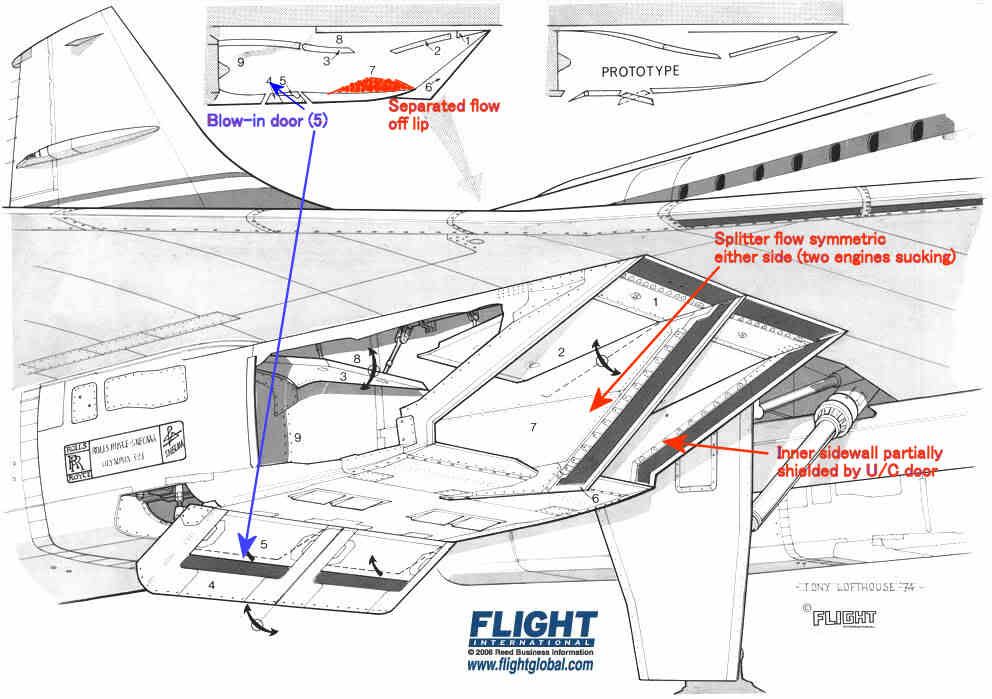
The intake leading edges were all sharp, so the flow would separate if subjected to a high AoA. The upper lip was protected a little by the wing leading edge, and we were obliged to modify the prototype LE ahead of the intakes to prevent underwing vortices developing at low AoA in cruise which also helped a bit.
The lower lip had a substantial separated flow 'bubble' at low forward speed as shown in red, but this cleared up quite quickly as the aircraft gathered speed. It was'cured' by the blow-in doors.
The inner sidewalls were shielded by the landing gear doors, so the AoAs on the sidewall on that side were quite modest.
The splitter was of course subject to equal flow demands on either side so the flow over that was pretty well symmetric.
That leaves the two outer sidewalls which, look for all the world like highly swept delta wings with sharp LEs mounted vertically.
Like all such wings when operated at high AoA they develop powerful vortices on the 'leeward' side. Looking back towards the engine the vortex on #4 engine was anticlockwise and that on #1 was clockwise. [Hope I got that one the right way round
]
The OL593 rotates clockwise looking aft so the induced incremental AoA on the compressor blades was different on #1 and #4. The difference was enough to trigger some mild blade vibration - hence the rpm restriction until the intake capture was good enough to reduce the vortex strength.
I don't think there is any published explanation, but maybe this will help.
Basically the problem with #4 intake was that it was on the RHS of the airplane. We are talking about low speed right? and especially zero forward speed when the engine is trying to suck as much air as it can get from wherever it can get it. That means that the induced angle of attack on all the intake leading edges is going to be high.
The best drawing I can find that shows the flow into the right hand pair is this
The intake leading edges were all sharp, so the flow would separate if subjected to a high AoA. The upper lip was protected a little by the wing leading edge, and we were obliged to modify the prototype LE ahead of the intakes to prevent underwing vortices developing at low AoA in cruise which also helped a bit.
The lower lip had a substantial separated flow 'bubble' at low forward speed as shown in red, but this cleared up quite quickly as the aircraft gathered speed. It was'cured' by the blow-in doors.
The inner sidewalls were shielded by the landing gear doors, so the AoAs on the sidewall on that side were quite modest.
The splitter was of course subject to equal flow demands on either side so the flow over that was pretty well symmetric.
That leaves the two outer sidewalls which, look for all the world like highly swept delta wings with sharp LEs mounted vertically.
Like all such wings when operated at high AoA they develop powerful vortices on the 'leeward' side. Looking back towards the engine the vortex on #4 engine was anticlockwise and that on #1 was clockwise. [Hope I got that one the right way round
]
The OL593 rotates clockwise looking aft so the induced incremental AoA on the compressor blades was different on #1 and #4. The difference was enough to trigger some mild blade vibration - hence the rpm restriction until the intake capture was good enough to reduce the vortex strength.
8th May 2013, 16:05
permalink Post: 1714
For the french speaking (or reading) people here, I just found a mine of very interesting informations about Concorde on this website:
Accueil
This site has a database of thousand of concorde flights with the following datas: Date and time of the flight, airframe used, technical and commercial crews, guests, departure/arrival airports and flight type (regular, charter world tour...).
On top of that, many infos and stories around Concorde can also be found there.
I can't resist to translate one of those stories (I'm far from being a native english speaker or a professional translator; so forgive me for the misspellings and other translation mistakes). It is a report about one of the biggest incident that happened to the prototype 001 during the flight tests:
Shock of shockwaves
We were flying with Concorde at Mach 2 since 3 month already on both side of the Channel. The prototype 001 did outstrip 002 which was supposed to be the first to reach Mach 2.
Unfortunately, a technical issue delayed 002 and Brian Trubshaw fairly let Andr\xe9 Turcat be the first to reach Mach 2 with the 001 which was ready to go.
The flight tests were progressing fast and we were discovering a part of the atmosphere that military aircrafts hardly reached before. With Concorde, we were able to stay there for hours although limited by the huge fuel consumption of the prototypes.
The Olympus engines did not reached their nominal performance yet and, most of the time, we had to turn on the reheat in supersonic cruise to maintain Mach 2.
The reheat is what we call afterburner on military aircrafts. Fuel is injected between the last compressor stage of the low pressure turbine and the first exhaust nozzle. This increases the thrust for the whole engine and its nozzle.
The 4 reheats, one for each engine, are controlled by the piano switches behind the thrust leavers on the center pedestal between the two pilots. Air was fed into the engines through 4 air intakes, one for each engine, attached 2 by 2 to the 2 engine nacelle, one under each wing. The advantage in terms of drag reduction was obvious.
However, tests in wind tunnel showed that, at supersonic speed, if a problem happens on one engine, there was a great chance for the adjacent engine to be affected as well by the shockwave interference from one air intake to the other despite the presence the dividing wall between the two intakes. So we knew that an engine failure at mach 2 would result in the loss of 2 engines on the same side, resulting in a lateral movement leading to a strong sideslip that would likely impact the 2 remaining engines and transform the aircraft into the fastest glider in the world.
This is why an automatic anti sideslip device was developed and installed on the aircrafts.
The air intakes are very sophisticated. At mach 2, it creates a system of shockwaves that slows down the air from 600 m/sec in front of the aircraft to 200 m/sec in front of the engine while maintaining a very good thermodynamic performance. In supersonic cruise, the engines, operating at full capacity all the time, were sensitive to any perturbation and reacted violently with engine surge: the engine refusing the incoming air.
Stopping suddenly a flow of almost 200kg of air per second traveling at 600m/sec causes a few problems. As a result, a spill door was installed under the air intake and automatically opened in such event.
To control the system of shockwaves and obtain an efficiency of 0,96 in compression in the air intake, 2 articulated ramps, controlled by hydraulic jacks, are installed on the top of the air intakes in front of the engines. Each ramp is roughly the size of a big dining room table, and the 2 ramps, mechanically synchronized, move up or down following the instruction of an highly sophisticated computer that adapts the ramp position according to the mach number, the engine rating and other parameters such as skidding.
At that time, it was the less known part of the aircraft, almost only designed through calculation since no simulator, no wind tunnel, did allow a full scale test of the system.
The control of the system was analog and very complex but it was not easy to tune and we were moving ahead with a lot of caution in our test at mach 2.
On the 26th of January 1971, we were doing a nearly routine flight to measure the effect of a new engine setting supposed to enhance the engine efficiency at mach 2. It was a small increase of the rotation speed of the low pressure turbine increasing the air flow and, as a result, the thrust.
The flight test crews now regularly alternate their participation and their position in the cockpit for the pilots.
Today, Gilbert Defer is on the left side, myself on the right side, Michel R\xe9tif is the flight engineer, Claude Durand is the main flight engineer and Jean Conche is the engine flight engineer. With them is an official representative of the flight test centre, Hubert Guyonnet, seated in the cockpit's jump seat, he is in charge of radio testing.
We took off from Toulouse, accelerated to supersonic speed over the Atlantic near Arcachon continuing up to the north west of Ireland.
Two reheats, the 1 and the 3, are left on because the air temperature does not allow to maintain mach 2 without them.
Everything goes fine. During the previous flight, the crew experienced some strong turbulence, quite rare in the stratosphere and warned us about this. No problem was found on the aircraft.
We are on our way back to Toulouse off the coast of Ireland. Our program includes subsonic tests and we have to decelerate.
Gilbert is piloting the aircraft. Michel and the engineers notify us that everything is normal and ready for the deceleration and the descent.
We are at FL500 at mach 2 with an IAS of 530 kt, the maximum dynamic pressure in normal use.
On Concorde, the right hand seat is the place offering the less possibility to operate the systems. But here, we get busy by helping the others to follow the program and the checklists and by manipulating the secondary commands such as the landing gear, the droop nose, the radio navigation, comms, and some essential engine settings apart from the thrust leavers such as the reheat switches.
The normal procedure consists in stopping the reheat before lowering the throttle.
Gilbert asks me to do it. After, he will slowly reduce the throttle to avoid temporary heckler. Note that he did advise us during the training on the air intake to avoid to move the thrust leaver in case of engine surge.
As a safety measure, I shut down the reheat one by one, checking that everything goes fine for each one. Thus I switch off the reheat 1 with the light shock marking the thrust reduction. Then the 3\x85
Instantly, we are thrown in a crazy situation.
Deafening noise like a canon firing 300 times a minute next to us. Terrible shake. The cockpit, that looked like a submarine with the metallic and totally opaque visor obviously in the upper position, is shaken at a frequency of 5 oscillation a second and a crazy amplitude of about 4 to 5 G. To the point that we cannot see anymore, our eyes not being able to follow the movements.
Gilbert has a test pilot reaction, we have to get out of the maximum kinetic energy zone as fast as possible and to reduce speed immediately. He then moves the throttle to idle without any useless care.
During that time, I try, we all try to answer the question: what is going on? What is the cause of this and what can we do to stop it?
Suspecting an issue with the engines, I try to read the indicators on the centre control panel through the mist of my disturbed vision and in the middle of a rain of electric indicators falling from the roof. We cannot speak to each other through the intercom.
I vaguely see that the engines 3 and 4 seem to run slower than the 2 others, especially the 4. We have to do something. Gilbert is piloting the plane and is already busy. I have a stupid reaction dictated by the idea that I have to do something to stop that, while I can only reach a few commands that may be linked to the problem.
I first try to increase the thrust on number 4 engine. No effect so I reduce frankly and definitively. I desperately look for something to do from my right hand seat with a terrible feeling of being helpless and useless.
Then everything stops as suddenly as it started. How long did it last, 30 seconds, one minute?
By looking at the flight data records afterward, we saw that it only last\x85 12 seconds!
However, I have the feeling that I had time to think about tons of things, to do a lot of reasoning, assumption and to have searched and searched and searched\x85! It looked like my brain suddenly switched to a fastest mod of thinking. But, above all, it's the feeling of failure, the fact that I was not able to do anything and that I did not understand anything that remains stuck in my mind forever.
To comfort me, I have to say that nobody among the crew did understand anything either and was able to do anything, apart from Gilbert.
The aircraft slows down and the engine 3 that seemed to have shut down restart thanks to the auto ignition system. But the 4 is off indeed.
Michel makes a check of his instruments. He also notes that the engine 4 has shut down but the 4 air intakes work normally, which makes us feel better. After discussing together, we start to think that we probably faced some stratospheric turbulence of very high intensity, our experience in this altitude range being quite limited at that time. But nobody really believes in this explanation. Finally, at subsonic speed, mach 0.9, with all instruments looking normal, we try to restart engine 4 since we still have a long way to go to fly back to Toulouse.
Michel launches the process to restart the engine. It restarts, remains at a medium rotation speed and shuts down after 20 seconds, leaving us puzzled and a bit worried despite the fact that the instrument indicators are normal.
Gilbert then decide to give up and won't try to restart this engine anymore and Claude leaves his engineer station to have a look in a device installed on the prototype to inspect the landing gear and the engines when needed: an hypo-scope, a kind of periscope going out through the floor and not through the roof.
After a few seconds, we can hear him on the intercom:
"Shit! (stuttering) we have lost the intake number 4."
He then describes a wide opening in the air intake, the ramp seems to be missing and he can see some structural damages on the nacelle.
Gilbert reacts rapidly by further reducing the speed to limit even more the dynamic pressure.
But we don't know exactly the extent of the damage. Are the wing and the control surfaces damaged? What about engine 3?
We decide to fly back at a speed of 250 kts at a lower altitude and to divert toward Fairford where our british colleagues and the 002 are based. I inform everybody about the problem on the radio and tell them our intentions. However, I add that if no other problems occur, we will try to reach Toulouse since we still have enough fuel.
Flying off Fairford, since nothing unusual happened, we decide to go on toward Toulouse. All the possible diversion airport on the way have been informed by the flight test centre who follows us on their radar.
At low speed, knowing what happened to us and having nothing else to do but to wait for us, time passes slowly, very slowly and we don't talk much, each one of us thinking and trying to understand what happened. However, we keep watching closely after engine 3.
Personally, I remember the funny story of the poor guy who sees his house collapse when he flushes his toilets. I feel in the same situation.
Gilbert makes a precautionary landing since we don't rely much on engine 3 anymore. But everything goes fine.
At the parking, there is a lot of people waiting for us and, as soon as the engines stop, we can see a big rush toward the nacelles of the right hand side engines.
Gilbert and myself are the first to get off the plane and we are welcomed down the stairs by Andr\xe9 Turcat and Jean Franchi who came out from the crowd watching at the right hand side nacelle.
They both behave the same way, with a slow pace attitude, the same look, a mix of disbelief and frustration.
Andr\xe9 is the first to speak: "I can't believe we were not on this flight, really unlucky\x85". Yes, this flight was supposed to be just a routine flight\x85!
The condition of the nacelle is impressive. We come closer and everybody move aside for us with a look of disbelief and respect as if we were hell survivors.
The ramps of the intake 4, those 2 "dining tables", have completely disappeared leaving a hole where we can see the hydraulic jacks and the stub rod where the ramps were attached.
Indeed, only the ramps were missing, apparently ejected forward which was unbelievable knowing how fast we were flying. The ramp slipped under the nacelle causing some damages on it and on the hood of one of the elevon's servo control. Fortunately, the control did not suffer any damage.
What is left of the rear ramp seems to be blocked down inside the intake in front of the engine and we can see behind it the first blades of the compressor, or what is left of it, not much.
The engine swallowed a huge amount of metal but no vital parts of the aircraft has been damaged, no hydraulic leaks, no fuel leaks. I remembered at that time the stories of some B58 Hustler accident where the loss of an engine at mach 2 almost certainly ended with the complete loss of the aircraft. Our Concorde has only been shaken. This incident strengthened the trust I had in this plane. And I was not unhappy to have experienced this ordeal, especially when I saw the frustration on the face of Andr\xe9 Turcat and Jean Franchi.
But we had to understand what happened and how; and also why the ramp's fixing broke.
It didn't take much time to get the answers.
I unintentionally triggered the problem when shutting down the reheat of engine 3. The sudden stop of the fuel flow did of course stop the combustion and the back pressure behind the low pressure turbine. But, probably because of the modification made on the engine before the flight, the stop of the reheat has not been followed by the normal closing movement of the primary nozzle to compensate the pressure drop. So the low pressure turbine ran out of control, dragging down the low pressure compressor which reacts by surging.
Despite the opening of the spill door, the engine surge led to a sudden movement of the shockwaves in the air intake creating a surge in the intake itself. A similar surge happened in the adjacent intake 4 followed by a surge of the corresponding engine. This caused an excessive pressure above the ramps and the fixings of the intake 4 did not hold.
Since it was the first time we experienced a surge in the air intake, we had little knowledge of the stress it would create on the ramps. This led to miscalculation of the strength of the ramps's frames and they did brake.
Another mistake: instead of installing the motion detectors on the ramp itself, to make the production easier, they have been placed on the arms of the hydraulic jacks. This is why Michel R\xe9tif thought that the position of the ramps were correct. The hydraulic jacks did not suffer any damage and were still working normally even if the ramps were missing.
All the data recorded during this event helped us in redesigning the air intakes and the flight test program resumed three month later.
After this, we deliberately created dozen and dozen of air intake surge to fine tune the way to regulate them with digital calculator this time.
From now on, even if it was still very impressive, it was safe and their intensity was not comparable with what we experienced with the missing ramps.
However, a french president may kept a lasting memory of this, much later, during a flight back from Saudi Arabia. This time, I was on the left side, Gilbert on the right and Michel was still in the third seat\x85 But that's another story.
For me, the lasting impression of failing and being helpless during this incident made me wonder what a commercial pilot would have done in this situation. This plane was designed to be handled by standard commercial pilots and not only by the flight test pilots.
At that time, I was interested in taking in charge the management of a training center for the pilots of the future Airbus's clients. This event pushed me that way and I made it clear that I wanted to add the flight training on Concorde in this project. This has been agreed and I did it.
And the Concorde training program now covers the air intake surges and how to deal with them.
Jean PINET
Former test pilot
Member and former president of the Air and Space Academy
Last edited by NHerby; 9th May 2013 at 17:24 .
8th Apr 2015, 20:40
permalink Post: 1856
Ruddman -
No autobrakes.
(And - with my pedant's hat on - no 'manual' brakes either. Pedal brakes, yes. I know that the 'manual brakes' has become an accepted term, but the nonsense of it just bugs me….)
Stopping distances were good; from a higher Vapp we stopped rather shorter than a 'classic' 747. Filton was tightish, Bournemouth was worse….
First gen carbon brakes did not like being 'feathered' so we used them pretty firmly on every landing. At Filton, Bournemouth, E Midlands etc. you'd put the pedals to the floor after nose wheel touchdown. Allegedly no more wear doing this than feathering them along a long runway.
Reverse was pretty effective - more so than a modern bypass engine. We idled the outboards at 100kts and the inboards at 75kts so they weren't in play for the whole landing (reverse is most effective at higher speeds anyway).
It was a good 'stopper'. Thankfully.
25th Feb 2016, 13:01
permalink Post: 1931
Tiny Items
Hi Dear Guys,
Amazing thread on an amazing aircraft! Red through all the posts. What an immense amount of knowledge/experience on this bird! Your valuable inputs triggerd my curiousity to the extent that I have started to study Concorde manuals trying to understand systems and operating details. Not an easy job! I think a more detailed Traning Manual would help me greatly.
Here is my question:
Going through the FM exterior inspection chapter I have run into tiny details what are really hard to find even on close-up external photos. Just to name a few: "nose gear free fall dump valve vent", "engine oil tank vent" or "hydraulic-driven fuel transfer pump drain". Was there a "pictorial" external inspection guide available on the Concorde for crew training (similar to Boeing or Airbus training aids)? If yes, could somehow, somebody send me a copy of that?
Appreciate your help,
Tamas