13th Aug 2010, 18:53
permalink Post: 4
Point taken GF, but it was discovered during development flying that that the Olympus 593 could be relit, given sufficient IAS, at almost any altitude within the normal flight envelope. The variable inlet would even be automatically scheduled, as a funcion of N1, in order to improve relight performance at lower Mach numbers. I certainly agree that you would decelerate and lose altitude fairly quickly under these conditions, however a multiple flame out was never experienced during the entire 34 years of Concorde flight testing and airline operation. There was, as a matter of interest an un-commanded deployment of a Concorde RAT AT MACH 2!! (The first indications of the event were when the cabin crew complained about 'a loud propeller sound under the rear cabin floor'. A quick scan of the F/E's panel revealed the truth of the matter). The aircraft landed at JFK without incident, and the RAT itself, apart from a very small leak on one of the hydraulic pumps, was more or less un-phased by the event. Although it sounds horrific, a prop rotating in a Mach 2 airstream, the IAS it 'felt' would be no more than 530 KTS at any time. The RAT was of course replaced before the aircraft flew back to LHR.
Not quite sure about your reference to the RAT on an F16 being Hydrazine powered; a Ram Air Turbine is just that, using the freely rotatting propellor to power hydraulics, electrics or both. Or do you mean the the F16 has an emergency power unit? Either way, it's fascinating stuff.
Yes, I do remember that the Germans used Hydrazine as a fuel during WW2: The father of one of our Concorde pilots was on an air raid to destroy one o the production plants there, this aviation business is such a small world.
20th Aug 2010, 12:06
permalink Post: 34
Biggles78
I know these fuel flows seem crazy (If take-off fuel flows had been maintained the endurance of the aircraft would have been about 55 minutes!!). But as the majority of the flight was carried out at Mach 2 and above, with the relatively miniscule fuel flows, you can see how we were able to cross the Atlantic with relative ease. It was the subsonic bit that was the pain.
The powerplant was as you say truly amazing. We had an, as yet, unmatched engine/intake combination, with a variable primary and secondary nozzles. The variable intake allowed supersonic operation with maximum pressure recovery, minimum aerodynamic drag, as well as extreme operational stability. (Extreme temperature shears, that would have caused surge/unstarts in military installations) were dealt with as a total non event). It's astonishing to believe, but at Mach 2 cruise, the intake provided approximately 63% of the powerplant thrust. It was controlled by the world's first airborne digital control system. (The system computers were built by the Guided Weapons Division of what was then BAC). The combination of the variable intake, plus the LP and HP compressors gave an overall compression ratio of 80:1.
The engine itself, being supplied with air at an ideal pressure, could run at an almost conststant TET, thanks to the variable primary nozzle. This also allowed N1 and N2 (corrected for total temperature) to be controlled more or less independently and run as close as possible to their separate surge lines throughout the entire flight envelope.
The variable secondary nozzle (wide open above Mach 1.1) allowed the jet efflux to gently expand against a cushion of air that was passed over the rear ramp of the intake, through the engine bay and into the annulus of the nozzle itself. This prevented thrust being wasted by the jet efflux widely splaying as it met ambient air that was at a pressure of as little as 1.04 PSIA.
It was this integrated powerplant that made true supersonic cruise possible
The airframe life issue was sort of like 'how long is a piece of string?'. The airframes are lifed in supersonic cycles, (which had been extended before, with modifications) and studies were always underway as far as further life extensions were concerned. (Basically the airframe was as tough as a brick outhouse in structural terms). The only real area of concern was the crown area (the roof
 ). There was a design flaw here in that the structure had not been designed fail-safe (allegedly by designed a Korean designer at A\xe9rospatiale who, it was said, went a bit loopy). When the FAA evaluated the design (in order for the aircraft to be registered in the USA, for Braniff operations out of IAD) they wanted 'crown planking' to be fitted externally, which would have added over a tonne to the weight of the aircraft, as well as producing some not inconsiderable drag. Fortunately a compromise was reached and additional NDT inspections were carried out, as well as more limited structural modifications. There was a long term, cost effective solution being studied, which would have cured the problem altogether. (The changes would have been mandated, over new requirements for ageing aircraft)
Nick Thomas
Nick, the whole expansion issue was one of the biggest issues that had to be addressed. Wiring looms would 'snake' in some underfllor areas to take up expansion, but the biggest difficulty of all were the mulitudes of hydraulic lines. These required sliding expansion joints, with of course seals to prevent leakage. When a seal deteriorated YPU GOT A LEAK!! (Fluid at 4000 PSI tends torun for freedom very quickly ). As far as fittings go, ChristiaanJ is quite right, you tried to anchor at one end only. I seem to remember that the passenger seat rails travelled over a roller afair. Fuel lines wer less of a problem, because their relative lengths were less.
I also agree wholeheartedly with ChristiaansJ's explanation about the 'friction' thing, I never really liked those stories. As a matter of interest, 127 deg's, for Mach 2, that would be at ISA +5 (-51.5 deg's C). Any warmer than that and we could not achieve Mach 2, due to the Tmo limit of 127. I remember one year, for several weeks we had unusually high north Atlantic temperatures; these impacted both the flight time AND the fuel burn. The further away you were from Mach 2, the higher the fuel consumption. (The faster you flew, the less fuel you burnt. How's that for a paradox?).
At ISA (-56.5 deg's C) temperatures, the total temperature was at around 118 deg's C.
ChristiaanJ
I remember the 17.5 degree position on the nose; it always looked as if the aircraft was trying to eat ants to me . I can not recall personally anyone removing the 12.5 deg' stops for access, although this could of course have been done on your side of the 'puddle' I guess.
As far as the APU ducting issue goes (hee, hee, not often we disagree Christiaan ) we are just going to have to agree to disagee about this, although I accept that two 4" diameter pipes (PLUS THERMAL INSULATION) might have done it, BUT I still stand by the other points.
Stlton
Unfortunately not; the keel beam area was extremely thin and there was not anywhere near enough room. Interesting solution on the 727 though, I never knew that one.
Quote:
Mate, if you could have seen my jaw drop when I read the T/O burn you would probably hurt yourself laughing to much. That is just incredible but the cruise flow seems like stuff all especially considering the speed. The idle flow was also a bit of a jaw dropper.

|
Quote:
| Was surprised, yet again, that Mach 2 was achieved without reheat. They really were/are an amazing powerplant. |
The engine itself, being supplied with air at an ideal pressure, could run at an almost conststant TET, thanks to the variable primary nozzle. This also allowed N1 and N2 (corrected for total temperature) to be controlled more or less independently and run as close as possible to their separate surge lines throughout the entire flight envelope.
The variable secondary nozzle (wide open above Mach 1.1) allowed the jet efflux to gently expand against a cushion of air that was passed over the rear ramp of the intake, through the engine bay and into the annulus of the nozzle itself. This prevented thrust being wasted by the jet efflux widely splaying as it met ambient air that was at a pressure of as little as 1.04 PSIA.
It was this integrated powerplant that made true supersonic cruise possible
Quote:
| On my list of regrets, not getting a flight on Concorde would be in the top 5. If they hadn't grounded them what sort of life did the airframes have left in them? |
). There was a design flaw here in that the structure had not been designed fail-safe (allegedly by designed a Korean designer at A\xe9rospatiale who, it was said, went a bit loopy). When the FAA evaluated the design (in order for the aircraft to be registered in the USA, for Braniff operations out of IAD) they wanted 'crown planking' to be fitted externally, which would have added over a tonne to the weight of the aircraft, as well as producing some not inconsiderable drag. Fortunately a compromise was reached and additional NDT inspections were carried out, as well as more limited structural modifications. There was a long term, cost effective solution being studied, which would have cured the problem altogether. (The changes would have been mandated, over new requirements for ageing aircraft)
Nick Thomas
Nick, the whole expansion issue was one of the biggest issues that had to be addressed. Wiring looms would 'snake' in some underfllor areas to take up expansion, but the biggest difficulty of all were the mulitudes of hydraulic lines. These required sliding expansion joints, with of course seals to prevent leakage. When a seal deteriorated YPU GOT A LEAK!! (Fluid at 4000 PSI tends torun for freedom very quickly
). As far as fittings go, ChristiaanJ is quite right, you tried to anchor at one end only. I seem to remember that the passenger seat rails travelled over a roller afair. Fuel lines wer less of a problem, because their relative lengths were less.
I also agree wholeheartedly with ChristiaansJ's explanation about the 'friction' thing, I never really liked those stories. As a matter of interest, 127 deg's, for Mach 2, that would be at ISA +5 (-51.5 deg's C). Any warmer than that and we could not achieve Mach 2, due to the Tmo limit of 127. I remember one year, for several weeks we had unusually high north Atlantic temperatures; these impacted both the flight time AND the fuel burn. The further away you were from Mach 2, the higher the fuel consumption. (The faster you flew, the less fuel you burnt. How's that for a paradox?).
At ISA (-56.5 deg's C) temperatures, the total temperature was at around 118 deg's C.
ChristiaanJ
I remember the 17.5 degree position on the nose; it always looked as if the aircraft was trying to eat ants to me
. I can not recall personally anyone removing the 12.5 deg' stops for access, although this could of course have been done on your side of the 'puddle' I guess.
As far as the APU ducting issue goes (hee, hee, not often we disagree Christiaan
) we are just going to have to agree to disagee about this, although I accept that two 4" diameter pipes (PLUS THERMAL INSULATION) might have done it, BUT I still stand by the other points.
Stlton
Quote:
|
Not to beat a dead horse, but, on the choice of location for APU, the 727 had a problem with this but for different reasons. Because of the location of the engines that were all mounted at the rear, the Aircraft was quite tail heavy and adding more weight with an APU in the tail section was not desirable.The solution found that I have not seen in any other Aircraft was to mount it in the wheel well transversely across the keel beam with the exhaust out and over the right wing. Quite unusual but it worked fine with the restriction that it could only be operated on the ground.
Its all academic now but, just out of curiosity could this have worked on the Concorde |
23rd Aug 2010, 13:20
permalink Post: 80
The reason that #4 engine was limited to 88% N1 on take-off was an interesting one, down to something known as 'foldover effect'. This was discovered during pre-entry into service trials in 1975, when quite moderate levels of first stage LP compressor vibrations were experienced at take-off, but on #4 engine only. Investigations revealed that the vibrations were as the result of vorticies swirling into #4 intake, in an anti-clockwise direction, coming off the R/H wing leading edge. As the engine rotated clockwise (viewed from the front) these vorticies struck the blades edgewise, in the opposite DOR, thus setting up these vibrations. The vorticies were as a result of this 'foldover effect', where the drooping leading edge of the wing slightly shielded the streamtube flowing into the engine intake. #1 engine experienced identical vorticies, but this time, due to coming off of the L/H wing were in a clockwise direction, the same as the engine, so were of little consequence. It was found that by about 60 KTS the vorticies had diminished to the extent that the N1 limit could be automatically removed. Just reducing N1 on it's own was not really enough however; some of this distorted airflow also entered the air intake through the aux' inlet door (A free floating inward opening door that was set into the spill door at the floor of the intake. It was only aerodynamically operated). The only way of reducing this part of the problem was to mechanically limit the opening angle of the aux' inlet door, which left the intake slightly choked at take off power. (The aux' inlet door was purely aerodynamically operated, and diff' pressure completely it by Mach 0.93).
Last edited by M2dude; 24th Aug 2010 at 08:31 . Reason: A few corrections
24th Aug 2010, 22:49
permalink Post: 101
ChristiaanJ
aaah yes, Max Climb/Max Cruise modes. I'd not forgotten this my friend, I was going to say a few words about that in a future post, but maybe we can do that now. (And I'd love to hear more of your comments on this here too, ChristiaanJ). The intake and autopilot modifications were in a way complimentary it's true, but really dealt with separate problems, at least in my view:
The intake control unit software change (a change to the control law that limited engine N1 as a function of intake local Mach number, Mo, and inlet total temperature, T1) was able to put an absolute limit on aircraft achievable Mach number during Mmo overshoots, but it would not PREVENT Mmo overshoots occurring altogether, it was more of a safety brake. This particular overspeed problem manifested itself well before route proving, and in fact the intake system 'fix' resulted in the Thrust Auto Reduce System being deleted, electronic control boxes and all. The TAR system was fitted on all development aircraft equiped with the digital intake system, and it tried (in vain) to limit extreme Mach overshoots. The production aircraft retained the TAR wiring and locked out circuit breakers, as well as two vacant spaces on the electronic racks. The prime reason for all these efforts were that some of the rapid excessive Mach overshoots quite often drove the intake into surge; the modification to this N1 limiter control enabled engine mass flow to be controlled in such a way that these surges could be prevented during temperature shears. The aircraft Mach limit was an extremely useful fringe benefit.
The AFCS mode change from what was Max Op and Max Op Soft (always loved that name) to Max Climb/Max Cruise was at a stroke able to deal with the regular Mmo overspeeds that kept on occuring during, as you say, the route proving trials of 1975, when British aircraft G-BOAC and the French aircrfraft F-BTSD carried out pre entry into service evaluation flights, SD sadly was the aircraft that was tragically lost at Gonez in July 2000). The Max Climb/Max Cruise AFCS mode combo is a mode like no other that I've personally seen before or since anywhere, (it for instance resulted an elsewhere taboo; an autopilot and an autothrotte working together IN A SPEED MODE).
This problem encountered primarily at lower lattitudes, (for example, G-BOAC doing route proving flights out of Singapore), occurring initially as the aircraft reached Mach 2. It was termed 'the insurmountable problem', but the AFCS designers (such as ChristiaanJ) fortunately did not have 'insurmountable problems' in their vocabulary. The issue was that the aircraft would have been climbing rapidly at Vmo of 530 KTS, with throttles at the gate as usual, At exactly 50,189' we hit what was known as 'the corner point' in the flight envelope, where 530 KTS IAS equated to Mach 2 exactly. Max Op mode would then 'let go' of the Vmo segment, and try and control the aircraft to Mach 2. (As the aircraft climbed, Vmo itself would progreesively decrease in order to equate to Mmo, or 2.04 Mach). But in very cold conditions, the aircraft still 'wanting' to accelerate, and the simple Max Op/Max Op Soft modes just could not cope with gentle pitch changes alone. The problem became even bigger during the cruise/climb when severe temperature shears occured, and routinely regular Mmo exceedences occured. Something had to be done, and something WAS done and how; enter Max Climb/Max Cruise. It was really a classic piece of design, where the aircraft would do the initial supersonic climb in Max Climb mode. This mode itself was relatively simple, in that it was more or less a Vmo -Vc hold mode. That meant that the difference at selection between indicated airspeed, Vc and Vmo would be maintained, with a vernier datum adjust to this being available. In practice this mode was selected pretty much at Vmo, so datum adjusting was not always required. Now comes the clever part; the autothrottle, this would operate in standy mode at this point, just waiting there doing nothing, with the throttles at maximum as before. So the aircraft would now climb as Vmo increased to 530 KTS, and then following a now constant Vmo of 530 KTS until the magic 'corner point' (51, 189' remember). Now all hell would break loose; the mode would automatically change to Max Cruise, the autothrottle would also be automaically selected to Mach Hold mode (initially datumed here to Mach 2) and the throttles would retard, attempting to hold this Mach 2 datum, and the autopilot is commands a 'fly up' signal, over a 20 second lag period to 600'/minute. Now comes an even cleverer (?) part; the autothrottle Mach Hold datum is gradually increased over a 100 second period towards Mach 2.02, and so in stable conditions the throttles would now gradually increase again until they once more reach the maximum limit. At this point, the autothrottles now come out of Mach Hold mode and back into the waiting in the wings standby mode. The autopilot would now cancel it's 600' fly up, demand, returning to a datum of Mach 2. There was a little more complexity built in also, where the difference between the 'commanded' and actual vertical speeds offset the autoplilot Mach 2 datum. This would apply whether the autothrottle had cut in (+600'/min demand) or with the throttles back at maximum (0'/minute demand. A positive climb error tweaked the cruise Mach up slightly, a negative error (eg. in a turn) the converse was true. The effect of all of this complexity was that the aircraft itself could 'scan' until it settled at a point where the throttles could be at maximum, and the speed between Mach 2 and 2.02. On the North Atlantic, with warmer ISA temperatures, there was usually just the initial routine with the autothrottle as you hit the corner point. However at lower lattitudes (eg. LHR BGI) there could be a few initial autothrottle intercepts before things settled down. This whole incredible routine completely took care of the insurmountable problem, a problem that was shown not only to be insurmountable, but was put to bed forever, by people like ChristiaanJ.
I hope that my explanation here does not sound too much like gibberish.
EXWOK
I think you've guessed right as far as my identity goes; it's great that it's not just Concorde pilots I can bore the socks off now
PS. I bet the ex-SEOs LOVED your comments
Dude
Last edited by M2dude; 25th Aug 2010 at 01:14 . Reason: missed out some info' (sorry)
8th Oct 2010, 14:18
permalink Post: 534
Feathers, these are the joys of afterburning; a totally gas guzzling way of extracting some more thrust from an engine. With Concorde, at 15 degrees TAT, you got a 78% increase in take off fuel flow for, as you say, about a 6000lb increase in thrust. Normaly adding an afterburning/reheat system is a fairly complex and heavy affair; you need both the system itself plus a variable exhaust nozzle. Because Concorde already required the primary nozzle for N1 control, the addition of reheat was at least a relatively simple and lightweight afair. The original Olympus 593-22R engine was really a little lacking in terms of dry thrust, and the addition of the reheat system was deemed essential. Concorde only had a single reheat spray ring and flame-holder, military systems often have several, with a corresponding increase in thrust growth as well as a hyper increase in fuel burn.
Further development plans for the Olypus 593 included a large increase in dry thrust; the reheat being retained only for transonic acceleration. It is such a pity that it was not to be.
Dude
Further development plans for the Olypus 593 included a large increase in dry thrust; the reheat being retained only for transonic acceleration. It is such a pity that it was not to be.
Dude
20th Oct 2010, 10:56
permalink Post: 594
Quote:
| What engine parameters were monitored to provide this indication and how was this done ? |
BLUE reverse light --- this reflected the correct operation of the
reverse thrust.
Flashing, rev selected but buckets in transit
On steady reverse selected and achieved
Amber Configuration
[CON] light----------- ON if reheat fails with no loss of engine RPM
On if reverse selected and primary nozzle greater
than 15%
Green Go light---------- This light monitored the engine for correct power
for take-off in that
Fuel flow and P7 had to match or exceed a pre
calculated figures, which were preset on their
individual gauges prior to take off.
The secondary nozzles had to within their
take-off limits
The CON light is off
In the case of No 4 engine the N1 limiter has
returned to normal position
Now normally there was a call of 100kts and at that point there had to be 4 green GO lights illuminated otherwise the t/off would be aborted. There was a concession to this in that if runway/ conditions /weight allowed the takeoff could continue with only 3 green lights illuminated at 100 kts as long as the
affected basic engine was OK[ this covered the loss of one reheat]
The green lights were considered necessary if the aircraft was using a rough runway and nose nodding could interfer with correct engine instruement monitoring and were also handy as the pilots could at a glance check whether they had at least minimum eng power for t/off.
To keep things simply their use was standard on all T/offs rough or otherwise
22nd Oct 2010, 09:26
permalink Post: 597
OK guys, here are the answers. If you disagree about any of them then fire away, the old memory certainly 'aint perfect.
As many of you have guessed, there were 22: The 14 production airframes, the 2 production series development aircraft (201 & 202), the 2 pre-production airframes (101 & 102) and the 2 prototypes 001 & 002. PLUS, the major fatigue test specimen at the RAE Farnborough and the static test specimen at CEAT in Toulouse. The CEAT tests actually tested the wing to destruction; I seem to remember it was something like a 200% overload before the wing failed at the root. And great but rather sad pictures
VOLUME
, never seen these before.
OK, from MY memory
 , we have: London LHR (duhhh!!), Bahrein BAH, Singapore SIN, New York JFK, Washington IAD, Dallas DFW, Miami MIA, Toronto YYZ, Barbados BGI, and Riyadh RUH. As well as charters being ommited, so are some of the special 'surprise' shuttle appearances that Concorde would make, substituting a subsonic to and from destinations such as Manchester and Edinburgh.
11:15
The BA193 and BA 195.
OK, there were 12 engine feed pumps (3 per engine) 8 main transfer tank pumps (2 each for the transfer tanks 5, 6, 7 & 8), 4 'A' tank pumps (2 each for 5A & 7A), 8 trim-transfer tank pumps (2 electric pumps each for tanks 9, 10 & 11 PLUS 2 hydraulically driven pumps for tank 9), 4 electric engine start pumps (there was a single electric start pump per engine that delivered fuel to it's own dedicated start atomiser in the combustion chamber. The pump automatically ran when the engine HP valve was set to OPEN and would continue running for 30 seconds after the DEBOW switch was returned to the 'normal' position), 4 engine first stage pumps (a single mechanically driven pump per engine), 4 second stage pumps (a single pneumatically driven pump, sometimes termed 'the turbopump, per engine. This would cut out at around 20,000'), our scavenge tank pump (triggered automatically when there was 7 US gallons in the tank; pumping it back into tank 2. This pump was identical to an 'A' tank transfer pump), and FINALLY, a single de-air pump for tank 10. The pump would drive the fuel through a mesh, removing air bubbles from the fuel. Tank 11 used the L/H trim pump for de-air (similar principle)and would be switched on during take-off. This is why the tank 5 trim inlet valve being set to over-ride OPEN would result in the tank being highly pressurised in the case of the Gonesse disaster; the pump would obviously pressurise the L/H trim gallery and any tank on that side with an open inlet valve!!!
G-AXDN, aircraft 101. (A production wing, fuselage, droop nose and intakes, but with the short tail section and secondary nozzles of the prototypes.
Ready ChristiaanJ? There were 18....Yes, the single SFENA standby horizon, 9 INS gyros (one per X,Y and Z platform in each of the 3 INUs), 8 autostab' rate gyros (one per axis for each of the 2 autostab' computers PLUS a monitor gyro for the pitch axis). The radar by the way used attitude signals from the INS.
9. One per main wheel plus the single 'in flight braking' nose wheel brake.
Mach 0.7!!! Between this and Mach 1.26 the intake surfaces were positioned as a function of engine N1 if the engine was shut down for any reason. (Otherwise of course the intake surfaces were fully up). You needed a sub idle N1 of 57% and below for all this to happen, and it was to assist relight performance and reduce buffet. Between Mach 1.26 and 1.32 the ramps were driven down slightly to about 5%, full supersonic scheduling itself commencing at Mach 1.32.
Already brilliantly answered by Brit312 (as well as the FSLabs diagram). Yep, Geen GO, T/O monitor armed, fuel flow and P7 at or above datum, A/C on ground, reverse not selected and CON light not on. Amber CON (Reheat selected and not detected, N1 OK or reverse selected and primary nozzle (Aj) not at minimum. Blue REV; steady buckets at reverse, flashing buckets in transit.
Fairford, followed by Brize Norton, and then a host of airfields from Prestwick and Shannon to Chateauroux.
OK, probably no surprises now:
Landing - 27L & R, 9L & R (prior to LHR mag' deviation update were 28L & R & 10L & R) together with 23/05.
Take off - 27L (28L), 9R (10R) and 9L. (10L never happened as take offs on this runway only occurred in 2003).
It was FedEx, they planned to operate two stripped out aircraft, leased from BA, between Shannon and JFK as high value parcel carriers. The idea was that parcels would be flown in from all over Europe by small FedEx feeder aircraft and the parcels transferred to Concorde which would then speed on to JFK in around 2 1/2 hours. It never happened because of a combination of economics appraisal by FedEx and BA deciding that it could would not release the aircraft anyway.
A/C 101, G-AXDN first flew on 17th December 1971 with FIXED INTAKES!! (101 was going to be the launch vehicle for the new digital intake control system, but the 'boxes' were still being designed). This placed an operating limit of Mach 1.5 on the aircraft, limiting her ability with such a restricted flight envelope. She returned to Filton in late 1972 for installation of the system, as well as the new Olympus 593-602 engine. (The engine, very similar to the production Mk 610 version, used a quite revolutionary annular combustion chamber, and eliminated at a stroke the thick smoke exhaust that had up to then been Concorde's unwanted visual signiture). The aircraft flew more or less smokeless on 15 March 1973, achieving Mach 2 soon afterwards. As ChristiaanJ pointed out, the British prototype 002 had a similar gap, actually significantly higher, of 19 months. (The French aircraft 001 had an even longer gap of some 20 months).
I hope you guys had fun with this one, regards to all
Dude
Quote:
| 1) How many Concorde airframes were built? |
Quote:
| 2) As far as the British constructed aircraft went, name the destinations that were served?. Regular flight numbers only, excludes charters etc. |
, we have: London LHR (duhhh!!), Bahrein BAH, Singapore SIN, New York JFK, Washington IAD, Dallas DFW, Miami MIA, Toronto YYZ, Barbados BGI, and Riyadh RUH. As well as charters being ommited, so are some of the special 'surprise' shuttle appearances that Concorde would make, substituting a subsonic to and from destinations such as Manchester and Edinburgh.
Quote:
| 3) What was the departure time for the ORIGINAL morning LHR-JFK Concorde services? (Not called the BA001 then either). |
Quote:
| 4) Further to question 3 above, what WERE the original flight numbers for the BA001 and BA003? (The morning and evening LHR-JFK services?). |
Quote:
5) There were no less than FORTY SIX fuel pumps on Concorde. What was the breakdown for these? (Clue; don't forget the scavenge pump
 ).
).
|
Quote:
| 6) What was the only development airframe to have a TOTALLY unique shape? |
Quote:
| 7) This one is particularly aimed at ChristiaanJ. What was the total number of gyros on the aircraft? |
Quote:
| 8) How many wheel brakes? |
Quote:
| 9) What Mach number was automatic engine variable intake control enabled? |
Quote:
| 10) Above each bank of engine instruments were three lights, a blue, a green and an amber. What did they each signify? |
Quote:
| 11) At what airfield were the first BA crew base training details held? |
Quote:
| 12) What LHR runways did Concorde use for landing and take-off? (Trick question, not as obvious as it might seem). |
Landing - 27L & R, 9L & R (prior to LHR mag' deviation update were 28L & R & 10L & R) together with 23/05.
Take off - 27L (28L), 9R (10R) and 9L. (10L never happened as take offs on this runway only occurred in 2003).
Quote:
| 13) What operator had serious plans to operate Concorde from SNN to JFK in the early 1980's? |
Quote:
| 14) What development aircraft did not exceed Mach 2 until fifteen months after her maiden flight? |
I hope you guys had fun with this one, regards to all
Dude
Last edited by M2dude; 22nd Oct 2010 at 11:21 . Reason: oops, misssed out question 2
24th Oct 2010, 22:18
permalink Post: 602
Consider it done Feathers.

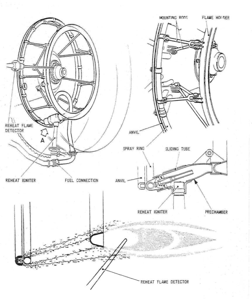
As promised, here are a few diagrams of the Concorde reheat (afterburner, for our American friends) system. The ORIGINAL design was done by SNECMA, but due to them getting into all sorts of trouble with the fuel injection system and flame stabilisation, Rolls Royce baled them out, and it became a Rolls Royce/SNECMA design. (The core engine was a 100% Rolls design, with no French input whatsoever. However some engine sub-assembles were manufactured by SNECMA).
The basic way the afterburner worked was by spraying the fuel FORWARDS intially at high pressure, against the jet stram about one inch, until it hit the anvil. . As the fuel strikes the anvil it is blown back by the jet stram and atomises, passing over the of the spray ring and the over the flame holder. The ignition operated by passing 15KV across a dual cylindrical tube, the resulting arc was 'swirlied' into the fuel stream by blowing engine 5th stage HP compressor air into the tube (there were 7 stages in all).
The key to successful ignition was a healthy spark, a good supply of air to the ignitor and accurate scheduling of fuel flow. (This was scheduled against dry engine flow as a funtion of total temperature). The other important factor (as with any afterburner) was correct and rapid operation of the exhaust nozzle. Fortunately, Concorde used it's primary nozzle for control of engine N1 anyway, so adapting this to operate as an afterburning nozzle also was a relative walk in the park, and it operated superbly.
During the light up phase of 3.5 seconds, the fuel ratio is a fixed 0.45 (ie. reheat fuel is 45% of dry fuel). After the light up phase the full scheduling commenced. As far as the FLIGHT RATING figures go (not take-off) the ratios were 0.6 at a TAT of 54 deg's C, falling linearly to 0.3 at 107 deg's C and above. (Remember that Concorde used afterburning really sparingly, just for take-off and then transonic acceleration; cut off at Mach 1.7 altogether.
Dude
29th Oct 2010, 19:13
permalink Post: 635
Brit312
mm I guess they were not to blame for flying for over one hour with a red throttle light on (the engine is under no electronic control), resulting in the severe engine overspeed (N1 overspeed protection amplifier already disabled) and the subsequent scrapping (on the orders of Rolls Royce) of the entire rotating assembly of the engine. Or for omitting TWO intake trunnion blocks during a ramp actuator replacement, and then the E/O continually and cyclically operating the intake lane selector switch, following a spill door runaway, until he manages a double engine surge and near destruction of the 'forgotton parts' intake and engine also. I suppose they are not to blame for the experimental tripping of the LPOG circuit breaker by the E/O, during an engine power mismatch, resulting in serious damage to the engine and intake due to the resulting massive over-fueling surge. I suppose again, that they were not to blame for ignoring
for over 6 months
a simple electrical load defect, eventually resulting in a not too minor fire in the electronics racks that had to be extinguished by the crew with extinguishers. And yet again, I suppose they are not to blame for putting skydrol into Concorde hydraulics systems, almost resulting in the loss of the aircraft, as well as a 9 month grounding while all of the hydraulic components were replaced. And it was not Air France that hammered Fox Delta twice into the runway at Dacca, resulting in so much airframe distortion that the aircraft performance was seriously compromised (and eventually broken up). And of course they were not responsible for the technical and operational failures, including the (forgotton
AGAIN
) missing spacer and overweight take-off etc.) on 25th July 2000. Silly me.
And although I might have said 'precautionary engine shut-down', we are talking about a quite an eventful episode here indeed, you can NOT excuse the further mistakes made on that day, 'just because they are poor old Air France. With the greatest of respect Brit, there are 3 crew members on that flight deck, do you not think that the loss of over over 5 tonnes of fuel over a period of time might just be noticed????? The subsonic 3 engined leg was carried out for quite a time before it computed to them that they were still losing fuel. There is no excuse for flying with your eyes closed, I'm sorry.
For goodness sake, this is probably the biggest single episode that was behind the demise of Concorde, poor Air France my eye!!!
Dude
Quote:
|
1] It seems to me thet poor old Air France are blamed when
1] They deviate from the checklist as was suggested in the crash OR 2] Stick to the checklist as in this case |
And although I might have said 'precautionary engine shut-down', we are talking about a quite an eventful episode here indeed, you can NOT excuse the further mistakes made on that day, 'just because they are poor old Air France. With the greatest of respect Brit, there are 3 crew members on that flight deck, do you not think that the loss of over over 5 tonnes of fuel over a period of time might just be noticed????? The subsonic 3 engined leg was carried out for quite a time before it computed to them that they were still losing fuel. There is no excuse for flying with your eyes closed, I'm sorry.
For goodness sake, this is probably the biggest single episode that was behind the demise of Concorde, poor Air France my eye!!!
Dude
Last edited by M2dude; 29th Oct 2010 at 22:55 . Reason: more spelling :-(
5th Nov 2010, 11:56
permalink Post: 663
I have to admit that some of the subsonic fuel burn figures for Concorde were truly eye watering, and without massive engine and airframe modifications there was precious little in service that could be done to improve things. Paradoxically improvements to the
supersonic
efficiency of the powerplant were easier to implement, and several modifications were implemented, tried or proposed to improve fuel burn:
Way back in the late 1970's we did a major modification to the intakes that increased capture area by 2.5% and gave us typically a 1.6% improvement in trans-Atlantic fuel burn, and although this was our biggest performance improvement modification, there were more:
The famous elevon and rudder trailing edge extension modifications (that due to poor design, produced in later life the water ingress induced honeycomb failures) together with the re-profiled fin leading edge modification, I never saw the performance gains quantified (anyone have any ideas?).
Can anyone here remember the riblet trial? In the mid 1990's Airbus supplied 'stick on' plastic riblets, applied to various areas on the under-side of the wing on G-BOAG. These riblets had very fine undulations moulded into the surface; the idea being that as the air flowed through and around the riblet patches, boundary layer turbulence, and hence induced drag would be reduced. Now, the performance gains (if any) were never quantified, mainly because the riblet patches either peeled off or the surface deteriorated with the continuous thermal cycle. (I was over in JFK when the aircraft first arrived after having the riblets fitted, and as the crew were trying to proudly show me these amazing aerodynamic devices, they were sadly embarassed, as several had dissapeared in the course of a single flight).
There was one modification, proposed by Rolls Royce in the late 1990's that did have quite a lot of potential; this was to increase the engine N1 by around 1.5%. This would have had the effect of increasing engine mass flow and therefore reducing the drag inducing spill of supersonic air over the lower lip of the intake. Depending on the temperature, the performance gains were in the order of a 1.5% improvement in fuel burn at ISA Plus upper atmosphere temperatures ('normal' LHR-JFK) to none at all at significant ISA Minus temperatures (LHR -BGI). The modifacation had been trialed on G-BBDG before her retirement in the early eighties, and was proven in terms of performance enhancement and engine stability. In order to keep TET at the pre-modification level, there was a small increase in N2 commanded also. (The higher N1 required an increase in primary nozzle area, reducing TET). The main reason for the modification not being implemented was one of cost; The Ultra Electronics Engine Control Units were analog units, and the modification was a simple replacement of two resistors per unit. However because ultimate mass flow limitation was also controll by the digital AICU (built by British Aerospace Guided Weapons Division) the cost of getting a software update for this exremely 'mature' unit was found to be prohibitive.
A certain 'brainy' SEO and myself were working on a modification to improve fuel burn on ISA minus sectors. The idea was to force the autopilot, in Max Cruise at low temperatures only , to fly the aircraft close to Mmo, rather than at Max Cruise speed of Mach 2 - 2.02; this would have given us gains of up to 1%, depending on the temperature. The basic electronics involved for the modification were relatively straightforward, but it was never pursued due to the complexity of dealing with temperature shears and the cost of certification.
Dude
Last edited by M2dude; 5th Nov 2010 at 15:49 .
17th Nov 2010, 03:44
permalink Post: 718
Hello all to all members and Concorde Expert,
I have been read this thread and it is so great. I'm enjoy reading it all day long!!
I have some question that I'm wonder about the Concorde.
1. I've heard that Concorde use the primary nozzle to modulate the noise and
the speed of the N1 compressor. How does it work? and does it help to reduce
the noise a lot?
2.Another thing about Primary nozzle. If i recall it correctly, the primary nozzle
can also use to control the Inlet Turbine temperature. Is that true? How is that work?
3.Finally, does some one have a schematic or the fuel vent system?
That's all of it. I will transform in to a nerd man reading a Concorde book in
the next couple days.
Thanks for all of yours reply.
18th Nov 2010, 00:32
permalink Post: 719
Mr Vortex
First of all, 'welcome aboard'; I'll do my best to answer your queries.
The area of the primary nozzle Aj, was varied for 2 'primary' purposes
:
a) To act as a military type 'reheat' or 'afterburning' nozzle; opening up to control the rise in jet pipe pressure P7, as reheat is in operated.
b) To match the INLET TOTAL TEMPERATURE RELATED (T1) speed of the LP compressor N1 to the HP compressor N2 against a series of schedules, ensuring easch spool is as close as safely possible to its respective surge boundary, (with a constant TET, see below) and therefore at peak efficiency.
Now, in doing this a complex set of variables were in place. As the nozzle is opened there is a REDUCED pressure and temperature drop across the LP turbine. This has the effect of enabling a HIGHER N1,as less work is being done by the turbine. Also the change (in this case a decrease) in the temperature drop across the turbine will obviously affect the turbine entry temperature, TET. A closing down of the nozzle would obviously have the opposite effect, with a DECREASE in N1 and an INCREASE in TET.
In practice at a given T1 there was always an ideal N1 versus N2 on the control schedule (known as the E Schedule), the TET staying more or less constant from TAKE-OFF to SUPERSONIC CRUISE!!
As far as noise abatement went; when reheat was cancelled and power reduced after take-off, an E Schedule known as E Flyover was automatically invoked. This had the effect of driving the primary nozzle nearly wide open, reducing both the velocity of the jet efflux and in essence the noise below the aircraft.
The real beauty of this primary nozzle system was that it really did not care if the engine was operating dry or with afterburning ('it' did not even know). P7 was controlled against a varying compressor outlet pressure, the variable being controlled by a needle valve operated by the electronic engine controller. (If this is unclear I can post a diagram here that shows this control in action).
As soon as I receive back the majority of my technical notes that I have out on long-term loan (I've requested their return) I will post a schematic here. But for now; The tanks were vented to atmosphere via tandem vent galleries, the two vents openings being on the left hand side of the tail-cone. At an absolute static pressure of 2.2 PSIA (around 44,000') twin electrically operated vent valves, also in the tail-cone, would automatically close; the tanks now being pressurised via a small NACA duct on the right side of the fin. A tank pressure of around 1.5 PSIG was maintained by the action of a small pneumatic valve at the rear of the aircraft. There was massive protection built in to guard against over-pressure (eg. if a tank over-filled in cruise).
I hope this answers some of your queries
Best Regards
Dude
Quote:
|
1. I've heard that Concorde use the primary nozzle to modulate the noise and the speed of the N1 compressor. How does it work? and does it help to reduce the noise a lot?
2.Another thing about Primary nozzle. If i recall it correctly, the primary nozzle can also use to control the Inlet Turbine temperature. Is that true? How is that work |
The area of the primary nozzle Aj, was varied for 2 'primary' purposes
:
a) To act as a military type 'reheat' or 'afterburning' nozzle; opening up to control the rise in jet pipe pressure P7, as reheat is in operated.
b) To match the INLET TOTAL TEMPERATURE RELATED (T1) speed of the LP compressor N1 to the HP compressor N2 against a series of schedules, ensuring easch spool is as close as safely possible to its respective surge boundary, (with a constant TET, see below) and therefore at peak efficiency.
Now, in doing this a complex set of variables were in place. As the nozzle is opened there is a REDUCED pressure and temperature drop across the LP turbine. This has the effect of enabling a HIGHER N1,as less work is being done by the turbine. Also the change (in this case a decrease) in the temperature drop across the turbine will obviously affect the turbine entry temperature, TET. A closing down of the nozzle would obviously have the opposite effect, with a DECREASE in N1 and an INCREASE in TET.
In practice at a given T1 there was always an ideal N1 versus N2 on the control schedule (known as the E Schedule), the TET staying more or less constant from TAKE-OFF to SUPERSONIC CRUISE!!
As far as noise abatement went; when reheat was cancelled and power reduced after take-off, an E Schedule known as E Flyover was automatically invoked. This had the effect of driving the primary nozzle nearly wide open, reducing both the velocity of the jet efflux and in essence the noise below the aircraft.
The real beauty of this primary nozzle system was that it really did not care if the engine was operating dry or with afterburning ('it' did not even know). P7 was controlled against a varying compressor outlet pressure, the variable being controlled by a needle valve operated by the electronic engine controller. (If this is unclear I can post a diagram here that shows this control in action).
Quote:
3.Finally, does some one have a schematic or the fuel vent system?

|
I hope this answers some of your queries
Best Regards
Dude
18th Nov 2010, 03:13
permalink Post: 721
Hi M2 Dude
Thanks very very much for your long reply and good explanation.
- So once we select the Engine schedule to mode Hi or F/O the Prim nozzle will
open wider causing the pressure at the Prim nozzle to drop and hence the
higher flow of the exhaust through the LP turbine = Higher N1 RPM.
Am I understand it correctly?
- According to your reply, the E schedule that will provide the most thrust is
the Low mode since the prim nozzle area will be the smallest among all of the
other mode which mean the highest pressure and temperature.
Am I understand it correctly? And if so why do BA [as far as I know] told the FE
to use Hi mode? Because the higher thrust can be obtain with higher N1?
- Also does the the Hi mode can deliver the higher N1 RPM, does that mean
the Engine control unit must deliver the higher fuelflow rate in order to keep
N2 run at the constant speed [higher N1 speed => higher pressure => more resistance
=> higher Fuelflow require to keep N2 run at constant speed]
Thanks for all of your reply!
Best Regards
Vortex
18th Nov 2010, 12:25
permalink Post: 724
Mr Vortex
More or less you are correct yes, but remember that schedule selection was more or less automatic. (
E Flyover
was armed prior to take-off, and
E-MID
during approach by the E/O, otherwise it was more or less a 'hands off' afair).
Oooo no, we are way adrift here I'm afraid. I'm trying not to get too 'heavy' with this explanation, and I've enclosed below the Rolls-Royce E Shedule diagram to try and help clarify everything. (I've edited out the exact equation figures in deference to Rolls-Royce). Where N1/√θ and N2/√θ is quoted, the term '
θ
' related to
T1 in degrees K/288
. (288 deg's K being 15 deg's C). The hotter things are the higher the spool speed scheduled is, and visa-versa for lower temperatures. Only at a T1 of 15 deg's. C (Standard day temperature) does N/√θ equate to N. (But remamber that T1 is TOTAL temperature, that varies with Mach Number).
The use of E LOW above 220KIAS was not only strictly inhibited by the automatics, if you over-rode the automatics and 'hard selected' E LOW , the aircraft would fall out of the sky when reheat was cancelled at Mach 1.7. This was because the low N1/√θ scheduled by E LOW would now invoke an N2/√θ limit (The E3 Limiter in the diagram) and claw off fuel flow by the tonne.
The most efficient schedule for supersonic cruise was E HI which again would be automatically selected.
E-MID was automatically selected during afterburning operation, to minimise the chance of an N1 overspeed on cancellation of reheat. E-MID could also be selected by the E/O for noise abatement approach.
E Flyover was as we discussed before used for take-off flyover noise abatement as well as subsonic cruise if desired. (If Mach 1 was exceeded with E Flyover still selected, a yellow NOZZLE light illuminated and E HI would be automatically selected.
I sincerely hope that this blurb is not clear as mud, feel free to ask away.
Nope, that is the beauty of it all. Because of the part choking of the LP turbine section of the engine, the pressure changes due to Aj variation were felt exclusively by N1 and not N2. (Clever, these Rolls-Royce guys
).
Regards
Dude

Quote:
| - So once we select the Engine schedule to mode Hi or F/O the Prim nozzle will open wider causing the pressure at the Prim nozzle to drop and hence the higher flow of the exhaust through the LP turbine = Higher N1 RPM. Am I understand it correctly? |
Quote:
| According to your reply, the E schedule that will provide the most thrust is the Low mode since the prim nozzle area will be the smallest among all of the other mode which mean the highest pressure and temperature. Am I understand it correctly? And if so why do BA [as far as I know] told the FE to use Hi mode? Because the higher thrust can be obtain with higher N1? |
The use of E LOW above 220KIAS was not only strictly inhibited by the automatics, if you over-rode the automatics and 'hard selected' E LOW , the aircraft would fall out of the sky when reheat was cancelled at Mach 1.7. This was because the low N1/√θ scheduled by E LOW would now invoke an N2/√θ limit (The E3 Limiter in the diagram) and claw off fuel flow by the tonne.
The most efficient schedule for supersonic cruise was E HI which again would be automatically selected.
E-MID was automatically selected during afterburning operation, to minimise the chance of an N1 overspeed on cancellation of reheat. E-MID could also be selected by the E/O for noise abatement approach.
E Flyover was as we discussed before used for take-off flyover noise abatement as well as subsonic cruise if desired. (If Mach 1 was exceeded with E Flyover still selected, a yellow NOZZLE light illuminated and E HI would be automatically selected.
I sincerely hope that this blurb is not clear as mud, feel free to ask away.
Quote:
|
- Also does the the Hi mode can deliver the higher N1 RPM, does that mean the Engine control unit must deliver the higher fuelflow rate in order to keep N2 run at the constant speed [higher N1 speed => higher pressure => more resistance
=> higher Fuelflow require to keep N2 run at constant speed] |
).
Regards
Dude
Last edited by M2dude; 18th Nov 2010 at 15:04 . Reason: I goofed.. (another sign of age)
19th Nov 2010, 22:00
permalink Post: 742
Mr Vortex
Not quite; remember that the N1s and N2s in the E SCHEDULE graph are non-dimentional. ie. they vary with temperature. As the temperature rises (with increasing Mach Number) the scheduled spool speeds increase. What really happens (I did not explain it correctly first time) is that the much lower N1 demanded by the use of E LOW at high speed results in a much further closed primary nozzle than normal, pushing up TET (and EGT) and we run hard into the EGT limiter, which claws fuel flow off, to the extent that the ramps and spill doors come down to their preset limits, almost as if there is a flame-out. The net result is a huge reduction in thrust. The condi was formed as the primary nozzle naturally took up a near fully open position in supersonic cruise and the wide open secondary nozzle buckets completed the picture. The schedule used here was E HIGH. I've noticed a couple of errors on the graph, the main one being that E HIGH is used with reheat off but with Vc
>
220 KIAS
Apart from being set as a variable limit, EGT normally played no role in the control loops (there were 2 loops, the 'governor' and 'positioner' loops). P7 played no part whatsoever in any case, the main variables were; N2, throttle valve position, throttle transmitter position, T1, total pressure and static temperature..
Feathers McGraw
Oh nooooo... I've been outed
Best regards
Dude
Quote:
|
So if we select E Low at M>1.7 the N2 will ovespeed and hence higher fuelflow. Am I understand it right? Also, what E mode provide the
best config shape [lest sat suitable] that provide a con-di nozzle for maximize thrust. [Not open to wide that exhaust can't reach M1 at the throat of Prim nozzle]. |
Quote:
| And another quesrion here, the engine control unit use which parameter to control the thrsut. The EGT, or N2, or P7. |
Feathers McGraw
Quote:
| If you watch some of the more recent Concorde programmes, such as "Concorde's Last Flight", you'll hear and see the reaction of the various people (including our very own Dude) from the BA side of things as they talk about their charge. |
Best regards
Dude
Last edited by M2dude; 20th Nov 2010 at 05:10 .
27th Nov 2010, 09:24
permalink Post: 791
Nick Thomas
Oh the Rolls Royce EGT Trend Monitoring Programwas an incredible piece of kit indeed Nick. The idea was that you would input Mach, TAT, N1, N2 and EGT itself. The computer program written in BASIC (I still have a copy) would then calculate the 'brochure' EGT for those conditions (the brochure itself being based on a 127\xb0 ISA +5 day), and what the
delta
from this brochure figure actually was. This delta EGT trend over the last few flights was then plotted (it was the delta rather than the actual brochure itself that we were interested in) and if there was a sudden jump or dip from the previous flights, it was indicative of something wrong with the engine. A severe dip was indicative of compressor damage and a severe jump indicative of turbine damage. Boroscope inspections would be carried out in such a case, and the Trend Program was better than 90% accurate in terms of predicting engine problems, although these problems became less and less common as the engine design became more mature. (As a result of modifications embodied in the engine over the years). FOD damage ended up being the most common cause of headaches here.
The obvious remedy for confirmed compressor or turbine damage was to 'pull' the engine and replace it with a 'new' one; the damaged engine was then sent to Treforest in Pontypridd for overhaul. (These guys by the way did a really superb job
).
Best Regards
Dude
Quote:
|
Looking at the readings it appeared that he had recorded a lot more readings than just the EGT. He also added that the readings were handed to the ground engineers at the end of each flight.
It would be interesting to know what readings were recorded and the significance of them to the ground engineers. Also could the FE deduce anything form the EGT trend graph? |
The obvious remedy for confirmed compressor or turbine damage was to 'pull' the engine and replace it with a 'new' one; the damaged engine was then sent to Treforest in Pontypridd for overhaul. (These guys by the way did a really superb job
).
Best Regards
Dude
Last edited by M2dude; 27th Nov 2010 at 09:39 .
1st Dec 2010, 14:04
permalink Post: 822
Well I have to say this is a brilliant thread.
I stumbled upon it by accident and been catching up on it when I had a spare moment and have found it completely riveting and it has whiled away many hours over the past month.
I\x92m ex-RAF and spent the last ten years working as an engine bloke on the T aeroplane & RB199. We were always told there were many parallels with Concorde & the Olympus 593 \x96 TBT/T7 Gauges, Optical Pyrometers, EPC Coils on-engine FCU\x92s, Vapour Core Pump for reheat fuel as well and the like. I attended the RR Manufactures course for two weeks at the Patchway Works and spent a day at the Concorde Museum seeing the similarities with the Electronic Control Units too though Lucas Aerospace made the MECU\x92s or GR1/4 (& DECU\x92s on the F3\x92s).
Also while on the course the distinguished RR Instructor Gent filled up in with various snippets of Engine History too such as the Vaporisers which were fitted to RB199 & the later models of Olympus 593 were originally Armstrong Sidderly designed for the Sapphire, also I learned the whole 15 Stage Sapphire Compressor was lifted completely and fitted to later Avon\x92s as it worked better.
I was at Leuchars in the early 80\x92s and the Open Golf peeps all arrived in one of these magnificent lady\x92s \x96 the visit was notable for several things; someone fired off an escape chute!!! \x96 What does this little handle do on the Main Oleo ??? whoosh ! and after the dusk take off the pilot beat the place up several times in full reheat !!!!
My last place of work before I was de-mobbed was at the RAF Marham Engine bay and I had the good fortune to meet an RR Technician called Phil (second name escapes me) but he was part of the team of RR Controls Engineers during the Hot & High Trials. He said they used to modify the three \x93Amps\x94 for each Engine control \x96 Lane1, Lane 2 & Reheat on the fly and the aircraft often flew with different schedules installed on all four engines \x96 I think the aircraft at Duxford has these still fitted in the racks (??M2Dude??) but that\x92s another Tonka thing too; three control lanes. Were all these Amps combined into one black box??
They are always Amps in RR Speak?? The Spey 202 had \x93Amps\x94 in its reheat system too.
I was lucky to find a job with the TVOC in 2001 until they ran out of money (as they do) and worked to have their flight worthy Olympus 20202\x92s tested at RR Ansty but left before that happened. In fact I don\x92t know if it did happen though it was a CAA requirement. While I was there we were working with Alan Rolfe & Mike Batchelor of the RR Historic Engine Department were offering support too. (593\x92s were their responsibility also !!! Historic !!!) but I think that was unofficial until there was an agreement about the costs.
After that I worked in industrial applications of Olympus (and Avon) and worked on many installed Olympus in power generation but based on the 200 Series \x96 I think the 300 was thought to be too fragile. But I did have a good look at Olympus 2008/003 Still in good working order in Jersey on the Channel Islands with it\x92s Bristol Sidderly Name plate on it. They didn't have Inlet Guide Vanes as the 300's had but just 6 Forward Bearing Supports, hollow with anti -Icing air blown though, controlled by a Garret Air Valve.
I never saw a DEBOW sort of function on the Industrials but there is a critical N1 speed which has to be avoided because the LP Turbine Disc can fail. The Trouble with that speed range is that it is right where the usefull power is produced!!! Was there any Normal Operating Range RPM's which had to be avoided on the 593 ?
Again thanks very much for all the fascinating information here\x92s to another 42 pages!!
Sorry to have rambled on so much

Howie
I stumbled upon it by accident and been catching up on it when I had a spare moment and have found it completely riveting and it has whiled away many hours over the past month.
I\x92m ex-RAF and spent the last ten years working as an engine bloke on the T aeroplane & RB199. We were always told there were many parallels with Concorde & the Olympus 593 \x96 TBT/T7 Gauges, Optical Pyrometers, EPC Coils on-engine FCU\x92s, Vapour Core Pump for reheat fuel as well and the like. I attended the RR Manufactures course for two weeks at the Patchway Works and spent a day at the Concorde Museum seeing the similarities with the Electronic Control Units too though Lucas Aerospace made the MECU\x92s or GR1/4 (& DECU\x92s on the F3\x92s).
Also while on the course the distinguished RR Instructor Gent filled up in with various snippets of Engine History too such as the Vaporisers which were fitted to RB199 & the later models of Olympus 593 were originally Armstrong Sidderly designed for the Sapphire, also I learned the whole 15 Stage Sapphire Compressor was lifted completely and fitted to later Avon\x92s as it worked better.
I was at Leuchars in the early 80\x92s and the Open Golf peeps all arrived in one of these magnificent lady\x92s \x96 the visit was notable for several things; someone fired off an escape chute!!! \x96 What does this little handle do on the Main Oleo ??? whoosh ! and after the dusk take off the pilot beat the place up several times in full reheat !!!!
My last place of work before I was de-mobbed was at the RAF Marham Engine bay and I had the good fortune to meet an RR Technician called Phil (second name escapes me) but he was part of the team of RR Controls Engineers during the Hot & High Trials. He said they used to modify the three \x93Amps\x94 for each Engine control \x96 Lane1, Lane 2 & Reheat on the fly and the aircraft often flew with different schedules installed on all four engines \x96 I think the aircraft at Duxford has these still fitted in the racks (??M2Dude??) but that\x92s another Tonka thing too; three control lanes. Were all these Amps combined into one black box??
They are always Amps in RR Speak?? The Spey 202 had \x93Amps\x94 in its reheat system too.
I was lucky to find a job with the TVOC in 2001 until they ran out of money (as they do) and worked to have their flight worthy Olympus 20202\x92s tested at RR Ansty but left before that happened. In fact I don\x92t know if it did happen though it was a CAA requirement. While I was there we were working with Alan Rolfe & Mike Batchelor of the RR Historic Engine Department were offering support too. (593\x92s were their responsibility also !!! Historic !!!) but I think that was unofficial until there was an agreement about the costs.
After that I worked in industrial applications of Olympus (and Avon) and worked on many installed Olympus in power generation but based on the 200 Series \x96 I think the 300 was thought to be too fragile. But I did have a good look at Olympus 2008/003 Still in good working order in Jersey on the Channel Islands with it\x92s Bristol Sidderly Name plate on it. They didn't have Inlet Guide Vanes as the 300's had but just 6 Forward Bearing Supports, hollow with anti -Icing air blown though, controlled by a Garret Air Valve.
I never saw a DEBOW sort of function on the Industrials but there is a critical N1 speed which has to be avoided because the LP Turbine Disc can fail. The Trouble with that speed range is that it is right where the usefull power is produced!!! Was there any Normal Operating Range RPM's which had to be avoided on the 593 ?
Again thanks very much for all the fascinating information here\x92s to another 42 pages!!
Sorry to have rambled on so much
Howie
2nd Dec 2010, 11:33
permalink Post: 823
howiehowie93
Welcome aboard and thank you for your kind words; I am so glad you enjoy our thread. You are in good company here also, many of the 'more mature' vintage Concorde people
(like me) are ex-RAF. (And some of the pilots were ex-RN also, but no one is perfect
... only joking guys).
It is a matter of pride/embarrassment for me that up to the end of 2003, I'd only ever really 'known' two aircraft; the C-130 and Concorde
.
I was really interested in some of the RB199/Olympus similarities; TBP was tried on the development aircraft for engine control TET calculation, but Rolls-Royce were unhappy with the performance and abandoned TBP in favour of indirectly computing TET as a function of T1 (intake TAT) and EGT (T7). (And this meant the removal of the four TBP amplifiers too... we had even more black boxes then.
As for the three 'control amps' you were speaking of, I'm 99% sure that A/C 101, G-AXDN still does have the units you described fitted. The ECUs (or ECAs as they were sometimes called) were a highly complex analog control unit built by Ultra Electronics. They could be quite a headache sometimes in terms of reliability, but would generally perform flawlessly in terms of engine control. As with any analog box, control law changes in the field were not too straightforward and a soldering iron was the flight test engineers best friend here. The Reheat Amp was built by ELECMA (the electronics arm of SNECMA) and unlike some of the other components in the reheat system, was a beautifully designed and constructed unit. Very few reheat failures (and there were many) were attributed to the 'box' itself. The main fragility with the reheat system was the ignition system used (a 20 KV swirl ignitor, which you will see is covered previously in the thread). We (BA/RR) were seriously looking at one point of investigatng the use of 'hot streak' injection as a backup ignition source, which I believe was used in the 199 (?), but it unfortunately never happened. The Plessey DECU that was tried on A/C 202 (G-BBDG) DID combine main engine control and reheat, but unfortunately was never taken up for the production A/C, and so we were left withe the '3 AMPS' as you so eloquently describe. We had a total of THIRTY ONE control units associated with powerplant control on Concorde; might be a little different now methinks
]
Thanks for some of the fascinating engine history snippets you shared with us, although purists might regard it as being 'off topic' I personally think this rather unique thread is all the better for your contribution here,
I think it is great that you are working with industrial Olympuses, all part of the family tree. I will dig out the verboten sustained N1 speed band for the 593, it certainly WAS a fact though.
Thanks from all of us for your contribution here Howie, keep on posting.
Regards
Dude
3rd Dec 2010, 12:19
permalink Post: 828
howiehowie93
The whole idea of adapting hotstreak injection came from our Rolls-Royce rep', who spent many years on RB199 development. We'd even identified the position on the Olympus 593 for the injector itself; un unused start atomiser port, but as I reluctantly said before, it was not to be.
Apart from ignition issues the other main problems were reheat instability and reheat 'coming in with a thump', this particular malady being generally confined to transonic acceleration and not take-off.
The instability issue was caused by either an open circuit/high resistance fuel metering valve tacho (only rate feedback was used here) or more commonly contamination of the RFCU umbilical electrical connector. The connector itself was originally located high up the side of the engine, close to the combustion area, was barely accessable and was a total nightmare in terms of reliability. After a great deal of pressure from us (BA) SNECMA agreed to effectively relocate the connector at the bottom of the engine and the majority of our stability problems almost disapperared overnight.
The 'reheat in with a thump issue was a real beaut'. For transonic acceleration a much lower ratio of Fr/Fe (reheat fuel flow/engine fuel flow) was used than for take-off. (0.45 as opposed to 0.78) and therefore the opening rate of the fuel metering valve required damping, this being achieved by using a metered orifice inside the RFCU that applied a small amount of servo fuel pressure to one side of the valve to achieve the damping. Trouble was, any contaminants in the reheat fuel system would progressively clog up the orifice and kill our daming stone dead; the end result being the FMV banging wide open and hence the 'thump'. The only remedy for this problem was to replace the RFCU. SNECMA, in a truly classic feat of engineering produced a filter across this orifice, in order to prevent it getting clogged. Anyone see a problem with this? Yep, the filter itself would clog up and we got our beloved thump back. The only remedy for this problem was again to replace the
RFCU. The contaminants were often as a result of RFCU build issues; this issue was never truly resolved.
The only remedy for this problem was again to replace the
RFCU. The contaminants were often as a result of RFCU build issues; this issue was never truly resolved.
I checked and found the dodgy sustained N1 band for the Olympus 593, this was 88-91% N1. This figure was never an issue in service as at cruise ISA -7 and above conditions the N1 was always run at the flat rate limit of 101.5%. Below ISA -7 the intake system would progressively reduce N1 as a function of intake local Mach Number, falling to 97.4% at ISA -24. (The coldest cruise conditions I personally ever saw was ISA - 25 (that's -81.5 degrees C folks) between BAH and BKK.
The controlled N1 at all other 'non cruise' phases was always in the upper 90's, well away from our blade resonance area.
jodeliste and Alpine Flyer
Thank you both for the TSR-2 information, it makes amazing reading (what a truly magnificent aircraft) , and as Concorde's military cousin, discussion here is in my opinion most waranted.
Regards
Dude
The whole idea of adapting hotstreak injection came from our Rolls-Royce rep', who spent many years on RB199 development. We'd even identified the position on the Olympus 593 for the injector itself; un unused start atomiser port, but as I reluctantly said before, it was not to be.
Apart from ignition issues the other main problems were reheat instability and reheat 'coming in with a thump', this particular malady being generally confined to transonic acceleration and not take-off.
The instability issue was caused by either an open circuit/high resistance fuel metering valve tacho (only rate feedback was used here) or more commonly contamination of the RFCU umbilical electrical connector. The connector itself was originally located high up the side of the engine, close to the combustion area, was barely accessable and was a total nightmare in terms of reliability. After a great deal of pressure from us (BA) SNECMA agreed to effectively relocate the connector at the bottom of the engine and the majority of our stability problems almost disapperared overnight.
The 'reheat in with a thump issue was a real beaut'. For transonic acceleration a much lower ratio of Fr/Fe (reheat fuel flow/engine fuel flow) was used than for take-off. (0.45 as opposed to 0.78) and therefore the opening rate of the fuel metering valve required damping, this being achieved by using a metered orifice inside the RFCU that applied a small amount of servo fuel pressure to one side of the valve to achieve the damping. Trouble was, any contaminants in the reheat fuel system would progressively clog up the orifice and kill our daming stone dead; the end result being the FMV banging wide open and hence the 'thump'. The only remedy for this problem was to replace the RFCU. SNECMA, in a truly classic feat of engineering produced a filter across this orifice, in order to prevent it getting clogged. Anyone see a problem with this? Yep, the filter itself would clog up and we got our beloved thump back.
The only remedy for this problem was again to replace the
RFCU. The contaminants were often as a result of RFCU build issues; this issue was never truly resolved.
I checked and found the dodgy sustained N1 band for the Olympus 593, this was 88-91% N1. This figure was never an issue in service as at cruise ISA -7 and above conditions the N1 was always run at the flat rate limit of 101.5%. Below ISA -7 the intake system would progressively reduce N1 as a function of intake local Mach Number, falling to 97.4% at ISA -24. (The coldest cruise conditions I personally ever saw was ISA - 25 (that's -81.5 degrees C folks) between BAH and BKK.
The controlled N1 at all other 'non cruise' phases was always in the upper 90's, well away from our blade resonance area.
jodeliste and Alpine Flyer
Thank you both for the TSR-2 information, it makes amazing reading (what a truly magnificent aircraft) , and as Concorde's military cousin, discussion here is in my opinion most waranted.
Regards
Dude
3rd Dec 2010, 13:37
permalink Post: 829
M2Dude
There was an unconfirmed report - so no doubt completely baseless - that ...er...another operator... noticed a rather unusual but highly favourable wind component on a JFK...er...Easterly... crossing, as they passed through FL520 or so, giving them a magnificent groundspeed.
Deciding that they would like to maintain this groundspeed, they went ALT HOLD and MACH HOLD at around FL530. They maintained their groundspeed, so the story goes, but the autothrottle then progressively reduced the N1, as the aircraft weight reduced, over the next couple of hours, into the prohibited range!
Did you ever hear of any such event?
Best Regards
Bellerophon
Quote:
| the dodgy sustained N1 band for the Olympus 593, this was 88-91% N1. This figure was never an issue in service as at cruise...the N1 was always run at the flat rate limit of 101.5%. Below ISA -7 the intake system would progressively reduce N1...falling to 97.4% at ISA -24 |
Deciding that they would like to maintain this groundspeed, they went ALT HOLD and MACH HOLD at around FL530. They maintained their groundspeed, so the story goes, but the autothrottle then progressively reduced the N1, as the aircraft weight reduced, over the next couple of hours, into the prohibited range!
Did you ever hear of any such event?
Best Regards
Bellerophon