4th Dec 2010, 09:17
permalink Post: 832
Bellerophon
Ahhh this 'other operator' (I'd quite forgotten our code for *** ******). And as for this obviously baseless story
 .... er yes it did happen. I should really have qualified my post and said 'The controlled N1
as long as the aeroplane was operated
CORRECTLY
was always at least in the upper 90's, well away from our blade resonance area'. I don't quite recall after the engines were removed post-flight (At Rolls-Royce's insistance) whether the entire LP compressor sections or just the first few stages had to be replaced at the engine overhaul base. In either case it was a rather expensive piece of experimentation.
.... er yes it did happen. I should really have qualified my post and said 'The controlled N1
as long as the aeroplane was operated
CORRECTLY
was always at least in the upper 90's, well away from our blade resonance area'. I don't quite recall after the engines were removed post-flight (At Rolls-Royce's insistance) whether the entire LP compressor sections or just the first few stages had to be replaced at the engine overhaul base. In either case it was a rather expensive piece of experimentation.
ChristiaanJ
Certainly my friend (but hey, remember that I'm an old Volts and Amps and Ohms ancient at heart too
 ).
).
The lighting of a reheat flame can be achieved in three ways:
1) By using an electric arc ignitor.. the least reliable system, although relatively simple in concept.
2) Catalytic ignition, where the reheat fuel is sprayed over a platinum based catalyst, spontaneously igniting. I recall that although generally reliable, eventually the catalyst compound erodes away and you are left with no ignition source.
3) Hot streak injection (or ignition). I this case a sizable jet of fuel is injected through a single injector placed the the combustion chamber of the engine, a powerful streak of flame then 'shoots out' of the turbine, and ignites the reheat fuel. Generally reliable as long as the injector itself does not carbon up (as our new friend Howiehowie93 pointed out). What amazed me with this system when we were looking at it for Concorde, was that the Olympus 593 designer I spoke to at Rolls-Royce told me that it has a negligible effect on turbine blade life, as the hottest part of the flame does not hit the blades themselves, and also of course it is a very short duration burn anyway (1 - 2 seconds).
And Christian my friend, you should indeed 'rabbit on' here about some of your observations regarding Concorde electronics technology, you have a unique insight here as (probably) the only Concorde systems designer that regularly visits 'here'. I'm sure I speak for many of us here when I say that your experiences are unique and your contributaions are always illuminating. Come on, let's have some Volts/Amps and Ohms
Best Regards
Dude
Quote:
| Deciding that they would like to maintain this groundspeed, they went ALT HOLD and MACH HOLD at around FL530. They maintained their groundspeed, so the story goes, but the autothrottle then progressively reduced the N1, as the aircraft weight reduced, over the next couple of hours, into the prohibited range!Did you ever hear of any such event? |
.... er yes it did happen. I should really have qualified my post and said 'The controlled N1
as long as the aeroplane was operated
CORRECTLY
was always at least in the upper 90's, well away from our blade resonance area'. I don't quite recall after the engines were removed post-flight (At Rolls-Royce's insistance) whether the entire LP compressor sections or just the first few stages had to be replaced at the engine overhaul base. In either case it was a rather expensive piece of experimentation.
ChristiaanJ
Quote:
| Can somebody explain to a "Volts and Amps and Ohms ancient" what "hotstreak injection" is/was (without getting scabrous)? |
).
The lighting of a reheat flame can be achieved in three ways:
1) By using an electric arc ignitor.. the least reliable system, although relatively simple in concept.
2) Catalytic ignition, where the reheat fuel is sprayed over a platinum based catalyst, spontaneously igniting. I recall that although generally reliable, eventually the catalyst compound erodes away and you are left with no ignition source.
3) Hot streak injection (or ignition). I this case a sizable jet of fuel is injected through a single injector placed the the combustion chamber of the engine, a powerful streak of flame then 'shoots out' of the turbine, and ignites the reheat fuel. Generally reliable as long as the injector itself does not carbon up (as our new friend Howiehowie93 pointed out). What amazed me with this system when we were looking at it for Concorde, was that the Olympus 593 designer I spoke to at Rolls-Royce told me that it has a negligible effect on turbine blade life, as the hottest part of the flame does not hit the blades themselves, and also of course it is a very short duration burn anyway (1 - 2 seconds).
And Christian my friend, you should indeed 'rabbit on' here about some of your observations regarding Concorde electronics technology, you have a unique insight here as (probably) the only Concorde systems designer that regularly visits 'here'. I'm sure I speak for many of us here when I say that your experiences are unique and your contributaions are always illuminating. Come on, let's have some Volts/Amps and Ohms
Best Regards
Dude
5th Dec 2010, 10:31
permalink Post: 836
This thread just gets better.
A couple of observations and a questionette, if I may? First, I'm feeling quite pleased with myself that I have largely understood the latest phases of discussion, re: Reheat Ignition and N1 resonance! To be fair I was a bit puzzled about 'Hot Streak' until Dude explained in a slightly different way. Then my first thought was; 'Cor crikey, isn't there enough heat on the turbine blades already?' It seems not, but it does raise the issue of TBE (TEB?) injection,
a la
SR71? I know the Blackbird used rather different fuel (JP8?), but is there not a similar chemical that would have done the same thing? Perhaps it was a reluctance to use 'exotic' chemicals in a civilian aeroplane?
The resonance issue is quite interesting, in that it appears to have affected all models of Olympus and was at roughly the same rpm on all. I take it that any attempt to damp specific frequency resonance would have adversely affected the performance?
Which brings me to my questionette - given that Bristol-Siddley created the original design when jet travel was still quite novel, what was it about the Olympus that made it so capable in so many guises and for so long? Not only Concorde of course, but TSR2, warships and fixed electrical generators.
Roger.
7th Dec 2010, 22:18
permalink Post: 840
Wow thanks a lot M2Dude for your diagram.

I'm wonder that did Concorde has a neutal of stable stability? Did the elevon work out the same job to produce the stability like the elevator and stabilizer?
Also, I have read your post and wonder why when the temp fall below ISA-7, the AICU order the N1 to decrese?
And the final question. In the early concorde, does the pilot has ability to select the amount of afterburn thrust by rotate the area knob is that right? and why the airline remove it?
Thanks for your reply.
Best Regards
8th Dec 2010, 18:05
permalink Post: 841
Landroger
The great thing about the OLY593 was the high specific thrust (in relative terms the Olympus is a tiny, compact design), it's growth potential/high potential mass flow. A bypass engine is not really ideal for supersonic cruise, and given what was available in terms of two-spool turbojets in the 1960s, the Olympus was the obvious choice for both the TSR-2 and Concorde alike. As far as for ships and power stations, well a turbojet is always going to be favourite, as all the gas energy is contained in the jet efflux; this can be efficiently transferred to the load in question by a gearbox coupled to the HP spool.
howiehowie93
Well the 593 did require a primary nozzle to match N1 against N2, bur apart from that she was a study of deceptive simplicity and elegance.
No mate, generally BI-HEX AF.
This really is fascinating stuff Howie, thank you. As I alluded to a few pages back, the primary nozzle on the OLY593 opened in response to the rising P7, kind of 'after the horse has bolted' in a way. To maintain the correct scheduled value of N1, the control system set, via a needle valve, a finite ratio between P7 and P3. As reheat lit as P7 attempted to rise it upset this ratio and the primary nozzle was opened in order to restore the aforementioned ratio. (Nozzle opens, P7 falls). When reheat was cancelled the opposite happened, and the nozzle closed sharply to prevent N1 overspeed.
Tom355UK
Glad you are enjoying our thread, and thank you for your kind words. (But apologies to your good lady wife though
).
Jeepers Tom that is one hell of a question. Assuming there was a market for such a venture (personally not sure right now) I think you are looking at BILLIONS of $, and for this reason alone I think you'd find that a multi-national/continental effort would be required. There is little doubt that technology is not the major barrier here, but economics and political will. (Nice thought though, I do agree).
As far as a powerplant goes, well the PW5000 is a really superb engine, although well down on the thrust requirement for an 'NG' SST. More likely I would have thought would be e development of the Olympus, there was/is still such an enormous amount of potential in this basic design. (But who knows, this is all pure speculation anyway).
And have no fears about posting here Tom, most of us are quite happy to answer away (We've said before that there is no such thing as a stupid question; you are most welcome here
).
DavvaP
It really did not matter what airframe we used for the test flight; the sole purpose was just to find out just what effect (if any) the tank liners had on the performance of the fuel system. (The handsome chap who you see on TV most, installing the liners, Mr Marc Morley left BA and now resides in Australia).
I am honoured to say that I was lucky enough to be onboard G-BOAF for that flight from LHR-BZZ and as far as I could tell, the liners had no impact whatsoever. One amusing part of the flight was when we deliberately allowed tank 3 to run dry and see just what the indicated fuel quantity was as #3 engine flamed out (we were subsonic at this point of course). The gauge slowly crept down (in order for the tank to to run dry, the tank 7 & 8 transfer pumps were switched off) and we all watched in eager anticipation/dread....... as the counters reached zero weeeeeee... the engine flamed out. I am being completely honest here, the engine wound down EXACTLY at
ZERO
indicated contents).
part of the flight was when we deliberately allowed tank 3 to run dry and see just what the indicated fuel quantity was as #3 engine flamed out (we were subsonic at this point of course). The gauge slowly crept down (in order for the tank to to run dry, the tank 7 & 8 transfer pumps were switched off) and we all watched in eager anticipation/dread....... as the counters reached zero weeeeeee... the engine flamed out. I am being completely honest here, the engine wound down EXACTLY at
ZERO
indicated contents).
Those 7 aircraft really did look magnificent I know, it was just sad as to the reason they were all lined up there.
Mr.Vortex
Well she was a delta without a tailplane, so the short answer is 'yes', but remember that we used fuel to move the CG backwards and forwards for long term trimming.
OK, this is a little complicated, so bear with me. The intake had a finite limit, in terms of the mass flow that it could deliver to the engine and so an automatic N1 limitation signal was transmitted from the intake 'box' (the AICU) to the engine 'box' (the ECU) full time above Mach 1.6. Now this limitation was referenced against TEMPERATURE compensated N1, (
N1/
\xd6
q)
and at normal ISA temperatures this limit was above the 'normal' 101.5% N1 running line. (The lower the temperature, the lower the effective limit became). At ISA -7 the limit now became less than 101.5% N1, and so the demanded value of N1 was reduced to this value. But this limit signal was always there, it's just that at normal temperatures it was effectively ignored by the ECU. If this limitation signal failed for any reason, the AICU would detect this by way of the ramp angle becoming uncomfortably close to it's MINIMUM variable limit (this limit was scheduled as a function of intake local Mach number) and an amber light would illuminate on the associated N1 gauge, along with an amber INTAKE master warning would illuminate (plus an audible 'BONG' from the audio warning system). The only course of action was to manually reduce throttle setting away from the Mach 2 norm of maximum, in order to reduce N2, and consequently N1 and mass flow demand. There was in intake pressure ratio indicator at the top of the intake control panel that would show where the power setting would have to be set to. It was an indirect indication of intake shock geometry.
This manual N1 datum reset control was only used during flight test trials into just how much N1 would have to be controlled/reduced at low temperatures in order to give optimim intake geometry. It had absolutely nothing to do with afterburner/reheat and had no place in the production aircraft as all the research was complete
Best regards to all
Dude
Quote:
| Which brings me to my questionette - given that Bristol-Siddley created the original design when jet travel was still quite novel, what was it about the Olympus that made it so capable in so many guises and for so long? Not only Concorde of course, but TSR2, warships and fixed electrical generators. |
howiehowie93
Quote:
| The Olympus - nowt ! Two Spools and a Fuel Valve thats your lot. nothing to go wrong and being an Aeroderivative all the ancillary equipment is either bolted on underneath or away from the engine outside the enclosure. |
Quote:
| Was it all still BSF on the 593? |
Quote:
| oh ! I forgot about the Hot Shot; when I was ground running installed RB199's there was no jump in TBT/T7, you couldn't sense it fire either, the only feel was either the Reheat lighting off with a big roar or the engine going quiet as the Nozzle opened up until the MECU noticed it hadn't lit and closed it again sharpish. |
Tom355UK
Quote:
| How much would it cost, do you think, that IF EADS really wanted to, using a combination of all the knowhow gained through L'Oiseau Blanc and their current lineup could they produce a 'Concorde NG'? Most importantly, would there be a market for such a beast (at the right price)? |
).
Jeepers Tom that is one hell of a question. Assuming there was a market for such a venture (personally not sure right now) I think you are looking at BILLIONS of $, and for this reason alone I think you'd find that a multi-national/continental effort would be required. There is little doubt that technology is not the major barrier here, but economics and political will. (Nice thought though, I do agree).
As far as a powerplant goes, well the PW5000 is a really superb engine, although well down on the thrust requirement for an 'NG' SST. More likely I would have thought would be e development of the Olympus, there was/is still such an enormous amount of potential in this basic design. (But who knows, this is all pure speculation anyway).
And have no fears about posting here Tom, most of us are quite happy to answer away (We've said before that there is no such thing as a stupid question; you are most welcome here
).
DavvaP
Quote:
| Ok, so my question is - BA had to use an airframe as a test for the modifications. However, the choice of airframe seemed a strange one to me, BOAF - which I previously thought to be one of the youngest and best airframe they had (m2dude you explained that BOAF and BOAG weighed less than the previous models). So, why would BA use one of their best airframes, rather than use perhaps the most worn out of their fleet? |
I am honoured to say that I was lucky enough to be onboard G-BOAF for that flight from LHR-BZZ and as far as I could tell, the liners had no impact whatsoever. One amusing
part of the flight was when we deliberately allowed tank 3 to run dry and see just what the indicated fuel quantity was as #3 engine flamed out (we were subsonic at this point of course). The gauge slowly crept down (in order for the tank to to run dry, the tank 7 & 8 transfer pumps were switched off) and we all watched in eager anticipation/dread....... as the counters reached zero weeeeeee... the engine flamed out. I am being completely honest here, the engine wound down EXACTLY at
ZERO
indicated contents).
Those 7 aircraft really did look magnificent I know, it was just sad as to the reason they were all lined up there.
Mr.Vortex
Quote:
| I'm wonder that did Concorde has a neutal of stable stability? Did the elevon work out the same job to produce the stability like the elevator and stabilizer? |
Quote:
| Also, I have read your post and wonder why when the temp fall below ISA-7, the AICU order the N1 to decrese? |
Quote:
| And the final question. In the early concorde, does the pilot has ability to select the amount of afterburn thrust by rotate the area knob is that right? and why the airline remove it? |
Best regards to all
Dude
29th Dec 2010, 11:21
permalink Post: 1038
That's a very 'Concorde' picture, Bellerophon.
Gentle descent in the crz, N1 max, N2 max, similar fuel burn per engine as a 747 (but over double the speed), Airspeed and Mach numbers just shy of the barber's poles, must have been well above FL500 given the Mach number yet the cabin alt is a smidge over 5000'.
Elapsed time 1hr 31, Longitude over 41W. Took me over three hours to get to 40W yesterday.......
PS and it has to be OAD, because for some reason the nose/visor control panel is black. I've no idea why I can remember stuff like that, but not the name of someone I met last week......
13th Jan 2011, 09:45
permalink Post: 1082
atakacs
Really an answer for CliveL, but I'll have a go. The short answer to your question is 'oh yeah, big time'. Total temperature varies with the SQUARE of Mach number and static temperature. Depending on the height of the tropopause itself as well as other local factors, there can be little or no significant variation of static temperature between FL600 and FL700. The 400\xb0K (127\xb0C) Tmo limit was imposed for reasons of thermal fatigue life, and equates to Mach 2.0 at ISA +5. (Most of the time the lower than ISA +5 static air temperatures kept us well away from Tmo). In a nutshell, flying higher in the stratosphere gains you very little as far as temperature goes. (Even taking into account the very small positive lapse above FL 650 in a standard atmosphere). As far as the MAX SPEED bit goes, Concorde was as we know flown to a maximum of Mach 2.23 on A/C 101, but with the production intake and 'final' AICU N1 limiter law, the maximum achievable Mach number in level flight is about Mach 2.13. (Also theoretically, somewhere between Mach 2.2 and 2.3, the front few intake shocks would be 'pushed' back beyond the lower lip, the resulting flow distortion causing multiple severe and surges).
On C of A renewal test flights (what I always called the 'fun flights') we DID used to do a 'flat' acceleration to Mach 2.1 quite regularly, as part of the test regime, and the aircraft used to take things in her stride beautifully. (And the intakes themselves were totally un-phased by the zero G pushover that we did at FL630). This to me was an absolute TESTAMENT to the designers achievement with this totally astounding aeroplane , and always made me feel quite in awe of chaps such as CliveL.
Well the maximum altitude EVER achieved in testing was I believe by aircraft 102 which achieved 68,000'. As far as the second part of your question goes, not to my knowledge (gulp!!) but perhaps CliveL can confirm.
Shaggy Sheep Driver
So glad you are enjoying the thread, and absolutely loved the description of your flight in OAD and your photo is superb. I don't think it is possible to name a single other arcraft in the world that could be happily flown hands off like this, in a turn with 20\xb0 of bank at Mach 2. (One for you ChristiaanJ; The more observant will notice that we are in MAX CLIMB/MAX CRUISE with the autothrottle cutting in in MACH HOLD. Oh, we are in HDG HOLD too ).
).
Now for your question
A very good question. The anti-skid system used a fixed simulated nose wheel rolling speed Vo signal as soon as the undercarriage was down and locked, this was confirmed by the illumination of the 8 'R' lights on the anti-skid panel. The illumination of these lights confirmed that there was full ant-skid release from the relevant wheel, due to there being of course zero output initially from the main gear tachos but this simulated Vo output from the nose gear tacho. The Vo signal therefore ensured that the aircraft could not be landed 'brakes on' (all the main wheels think they are on full skid) and that there was anti-skid control pending lowering of the nose-wheel. As the main wheels spin up on landing, their tacho outputs now start to back off the Vo signal, and braking can commence. As the nose leg compresses, the Vo signal is removed and the Nose-wheel tachos(their were 2 wired in parallel) spin up, their output will now replace the Vo signal, and full precise anti skid operates.
As far as your air conditioning question goes, you needed an external air conditioning truck to supply cabin air on the ground. Not needed in the hangars of course, but come departure time if these trucks were not working, then the cabin could become very warm/hot place indeed (depending on the time of year). Oh for an APU
Best regards
Dude
Quote:
| Just wondering was that the maximum speed "in" the design ? I understand that "the higher & the colder = the faster" was the key to the performance and that the Mach +/- 2.0 cruise was implied by limiting altitude to FL 600 in order to mitigate cabin depressurization consequences. I guess there where also thermal issues but was, say, Mach 2.2 @ FL700 "warmer" than Mach 2.0 @ FL600 ? |
Really an answer for CliveL, but I'll have a go. The short answer to your question is 'oh yeah, big time'. Total temperature varies with the SQUARE of Mach number and static temperature. Depending on the height of the tropopause itself as well as other local factors, there can be little or no significant variation of static temperature between FL600 and FL700. The 400\xb0K (127\xb0C) Tmo limit was imposed for reasons of thermal fatigue life, and equates to Mach 2.0 at ISA +5. (Most of the time the lower than ISA +5 static air temperatures kept us well away from Tmo). In a nutshell, flying higher in the stratosphere gains you very little as far as temperature goes. (Even taking into account the very small positive lapse above FL 650 in a standard atmosphere). As far as the MAX SPEED bit goes, Concorde was as we know flown to a maximum of Mach 2.23 on A/C 101, but with the production intake and 'final' AICU N1 limiter law, the maximum achievable Mach number in level flight is about Mach 2.13. (Also theoretically, somewhere between Mach 2.2 and 2.3, the front few intake shocks would be 'pushed' back beyond the lower lip, the resulting flow distortion causing multiple severe and surges).
On C of A renewal test flights (what I always called the 'fun flights') we DID used to do a 'flat' acceleration to Mach 2.1 quite regularly, as part of the test regime, and the aircraft used to take things in her stride beautifully. (And the intakes themselves were totally un-phased by the zero G pushover that we did at FL630). This to me was an absolute TESTAMENT to the designers achievement with this totally astounding aeroplane , and always made me feel quite in awe of chaps such as CliveL.
Quote:
| Also wondering what was the max altitude ? Was high altitude stall (for the lack of a better word) ever experimented during tests or training ? |
Shaggy Sheep Driver
So glad you are enjoying the thread, and absolutely loved the description of your flight in OAD and your photo is superb. I don't think it is possible to name a single other arcraft in the world that could be happily flown hands off like this, in a turn with 20\xb0 of bank at Mach 2. (One for you ChristiaanJ; The more observant will notice that we are in MAX CLIMB/MAX CRUISE with the autothrottle cutting in in MACH HOLD. Oh, we are in HDG HOLD too
).
Now for your question
Quote:
| I understand that the anti-skid used a rotational reference from the unbraked nosewheels to compare to the rotation of the mains, and that with gear down in the air a substiute nose-wheel referance is supplied which, because the mains are not yet rotating, allows the anti-skid to keep the brakes off. But what happens when the mains touch down with the nose wheels still high in the air? What (if anything) inhibits wheel braking until the nosewhels are on the ground (and therefore rotating)? |
As far as your air conditioning question goes, you needed an external air conditioning truck to supply cabin air on the ground. Not needed in the hangars of course, but come departure time if these trucks were not working, then the cabin could become very warm/hot place indeed (depending on the time of year). Oh for an APU
Best regards
Dude
13th Jan 2011, 11:10
permalink Post: 1083
Quote:
|
Originally Posted by
M2Dude
Really an answer for CliveL, but I'll have a go. The short answer to your question is 'oh yeah, big time'. Total temperature varies with the SQUARE of Mach number and static temperature. Depending on the height of the tropopause itself as well as other local factors, there can be little or no significant variation of static temperature between FL600 and FL700. The 400\xb0K (127\xb0C) Tmo limit was imposed for reasons of thermal fatigue life, and equates to Mach 2.0 at ISA +5. (Most of the time the lower than ISA +5 static air temperatures kept us well away from Tmo). In a nutshell, flying higher in the stratosphere gains you very little as far as temperature goes. (Even taking into account the very small positive lapse above FL 650 in a standard atmosphere). As far as the MAX SPEED bit goes, Concorde was as we know flown to a maximum of Mach 2.23 on A/C 101, but with the production intake and 'final' AICU N1 limiter law, the maximum achievable Mach number in level flight is about Mach 2.13. (Also theoretically, somewhere between Mach 2.2 and 2.3, the front few intake shocks would be 'pushed' back beyond the lower lip, the resulting flow distortion causing multiple severe and surges).
On C of A renewal test flights (what I always called the 'fun flights') we DID used to do a 'flat' acceleration to Mach 2.1 quite regularly, as part of the test regime, and the aircraft used to take things in her stride beautifully. (And the intakes themselves were totally un-phased by the zero G pushover that we did at FL630) |
As usual Dude you beat me to it! I really must give up having another life

As Dude says, the 'cruise' condition was set by the aircraft specification for transatlantic range on an 85% (ISA +5) day and the chosen mach Number was 2.0 (of which more anon). This gives a Total Temperature of 400.1 deg K. [Dude, I know your pipe-smoking thermodynamicist and he was having you on - he is quite capable of memorising the square/square root of 407.6 or whatever!]
To give margins for sudden changes in ambient temperature (we had to cater for a 21 deg change in one mile) the Mmo was set at 2.04 which matches 400 degK at ISA +1. In theory then we could have flown faster than our chose Mmo at anything colder than this, but there are two limits:
1) The object is not to fly as fast as you can but to fly with minimum miles/gallon. If you have a nice cold day and enough thrust to go either faster or higher which do you choose? For best specific range you go higher every time.
2) The thing that everyone forgets is that civil aircraft have to have margins around their authorised envelope. In Concorde's case these were set principally by the intake limits and engine surge.
Dude also says quite correctly that 101 flew to 2.23M but the production aircraft was limited to 2.13M. Now you may not believe this, but 101 could fly faster than the production aircraft because she (101) leaked like a sieve!.
I doubt I will get away with that without some explanation

Once you get past a certain Mach Number the airflow into the intake is fixed. The performance (intake pressure recovery and engine face flow distortion) then depends on how this air is shared between the engine and the throat 'bleed'. This bleed was ducted over the engine as cooling air and then exhausted (in principle) throught the annulus formed between the expanding primary jet and the fixed walls of the con-di nozzle. But if you took, or tried to take, more bleed air the intake pressure recovery went up and the primary jet pipe pressure went up with it. This meant that the primary jet expanded more and squeezed the available annulus area which restricted the amount of bleed air one could take.
Obviously if there are alternative exit paths between intake and final nozzle then you can take more bleed air off and the engine face flow distortions will benefit along with the surge margin. 101 was fairly 'leaky' in this respect, particularly around the thrust reverser buckets on the original nozzle design. This meant that 101's intake distortions were lower than the production aircraft so she could fly faster without surge - at least with the first attempt at intake control 'laws'. We managed to tweak most of the margin back eventually. Engine bay leaks were good for surge margin but VERY bad news for m.p.g.!
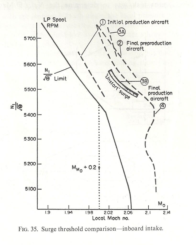
Here are a couple of diagrams to show what I mean. the first shows the surge lines for the various aircraft variants and also the N1 limiter Dude was talking about. NB: the X-axis is LOCAL Mach Number not freestream. The difference comes from the compression of the underwing flow by the bit of the wing ahead of the intake. Mmo + 0.2 is shown
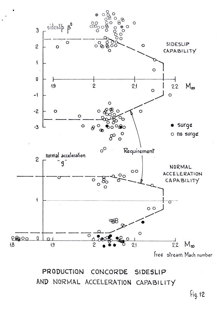
 ">The next shows the surge free boundaries in sideslip and normal acceleration. You can see the zero 'g' capability Dude was enthusing over.
 ">
">
As for 'high speed stall', I don't think we ever contemplated trying it! Our requirements in 'g' capability were defined and that was it. Besides, the aircraft would fly like the proverbial stone-built outbuilding at those sorts of conditions so I don't think one would have been able to get anywhere near a stall in the conventional sense. Stall as commonly defined for subsonics (deterrent buffet) might have been another matter, but I don't remember anything.
Cheers
Last edited by CliveL; 13th Jan 2011 at 11:17 . Reason: additional explanation
6th Apr 2011, 19:43
permalink Post: 1265
Hello skyhawkmatthew!
M2dude gave a good answer on your question in post #1085, so I think I may quote this here again.
M2dude gave a good answer on your question in post #1085, so I think I may quote this here again.
Quote:
|
Originally Posted by
M2dude
As far as the MAX SPEED bit goes, Concorde was as we know flown to a maximum of Mach 2.23 on A/C 101, but with the production intake and 'final' AICU N1 limiter law, the maximum achievable Mach number in level flight is about Mach 2.13. (Also theoretically, somewhere between Mach 2.2 and 2.3, the front few intake shocks would be 'pushed' back beyond the lower lip, the resulting flow distortion causing multiple severe and surges).
The maximum altitude EVER achieved in testing was I believe by aircraft 102 which achieved 68,000'. |
7th Apr 2011, 20:56
permalink Post: 1274
Not quite right: the reheats ignite if
(At temperatures colder than -35\xb0C the engine control schedule limits the N1 of all engines to 88% or less.)
Regards
- throttle lever >10% open; at takeoff the throttle levers have to be slammed to fully open within a second
- selected RHT or CTY
- N1 >81%
(At temperatures colder than -35\xb0C the engine control schedule limits the N1 of all engines to 88% or less.)
Quote:
|
Originally Posted by
Brit312
Up to 60 kts the F/E could reselect a failed reheat so hoping it would be OK by 100kts
|
Last edited by Quax .95; 11th Apr 2011 at 16:34 . Reason: T/O-case added
7th Apr 2011, 22:15
permalink Post: 1276
This might be because the #4 engine accelerates less fast than the others due to the limiter, reaching 81% N1 a little bit later. But this thread is too brilliant for presumptions (don't want to repeat the mistake of my first post...
). Let's see what the Concorde-geniuses add.
). Let's see what the Concorde-geniuses add.
Last edited by Quax .95; 8th Apr 2011 at 23:53 . Reason: spelling
8th Apr 2011, 07:13
permalink Post: 1280
Jane-DoH
One of the real beauties of the Concorde intake was that it was completely self-startiing, and so unstarts as such were never heard of.
Regarding the vibrations thing, here is my post #80:
I seem to remember that Rolls Royce proposed a solution of their own, whre the right hand pair of engines would rotate ant-clockwise (viewed from the front) rather than the clockwise norm for just about any 'Roller' that I can think of. Although this would have completely solved the vibration problem, and was great business for the folks at RR in Patchway (just about doubling the required number of engines) it was a pretty lousy idea if you were an airline and required a much latger holding of spare engines.
One of the real beauties of the Concorde intake was that it was completely self-startiing, and so unstarts as such were never heard of.
Regarding the vibrations thing, here is my post #80:
Quote:
| The reason that #4 engine was limited to 88% N1 on take-off was an interesting one, down to something known as 'foldover effect'. This was discovered during pre-entry into service trials in 1975, when quite moderate levels of first stage LP compressor vibrations were experienced at take-off, but on #4 engine only. Investigations revealed that the vibrations were as the result of vorticies swirling into #4 intake, in an anti-clockwise direction, coming off the R/H wing leading edge. As the engine rotated clockwise (viewed from the front) these vorticies struck the blades edgewise, in the opposite DOR, thus setting up these vibrations. The vorticies were as a result of this 'foldover effect', where the drooping leading edge of the wing slightly shielded the streamtube flowing into the engine intake. #1 engine experienced identical vorticies, but this time, due to coming off of the L/H wing were in a clockwise direction, the same as the engine, so were of little consequence. It was found that by about 60 KTS the vorticies had diminished to the extent that the N1 limit could be automatically removed. Just reducing N1 on it's own was not really enough however; some of this distorted airflow also entered the air intake through the aux' inlet door (A free floating inward opening door that was set into the spill door at the floor of the intake. It was only aerodynamically operated). The only way of reducing this part of the problem was to mechanically limit the opening angle of the aux' inlet door, which left the intake slightly choked at take off power. (The aux' inlet door was purely aerodynamically operated, and diff' pressure completely it by Mach 0.93). |
8th Apr 2011, 16:29
permalink Post: 1284
For take-off reheat was selected (armed) on all 4 engines together, and certainly not in pairs. (As was stated previously, once 81% N1 was reached the reheat light-up sequence was automatically initiated). You would not wind up on the brakes either, the carbon brakes were extremely sensitive to overtorquing. For transonic acceleration however you are quite right about the 'burners in pairs' bit.
Last edited by Jetdriver; 10th Apr 2011 at 09:23 .
9th Sep 2011, 19:27
permalink Post: 1450
Saw BOAG this weekend
I was in Seattle for a wedding this weekend, and got to see BOAG at the Museum of Flight.
It was gratifying, but I can't say she's in stellar condition. I'd give her a solid "B" grade. For one thing, it drives me nuts that all the literature and display placards all say "the Concorde." I far prefer Concorde to stand on her own. Her paint was dull and oxidized, and the exhibit sort of stands alone, without much in the way of history or surrounding material. It pained me a bit to see her outside in the Seattle weather, too. The interior is nice, being cordoned off by plexiglass that could stand a replacement sometime soon. I didn't see peeling paint.
That said, it was a spectacularly more enjoyable experience than the last time I saw Concorde F-BVFA at the Udvar Hazy museum in DC, thanks completely to this thread. I noticed things I'd never seen before, and took a much more profound appreciation of things like the curve and droop of the wing leading edge and the complexity of the engine intakes... and I loved seeing the difference in fuel consumption numbers between Concorde and the SR-71 also on display. My wife thinks I'm a genius because I knew why #4 engine was N1 limited below 60kt and what the little 3/4 tag to the left of the engine EGT gauges was for.
Thanks again to all the knowledgeable individuals on this thread.
9th Sep 2011, 19:45
permalink Post: 1451
Quote:
|
Originally Posted by
asc12

My wife thinks I'm a genius because I knew why #4 engine was N1 limited below 60kt and what the little 3/4 tag to the left of the engine EGT gauges was for.
|
16th Jul 2016, 17:01
permalink Post: 1944
According to this, 5500-6000 feet/1700 meters
Heritage Concorde
IIRC from one of the previous posts here, the strong differential required also defined the normal descent/deceleration timing and distance.
Power could only be reduced to 94% (N1 or N2, I forget which) or there would not be enough "bleed" air available to maintain the cabin altitude at TOD.
(although I could have misinterpreted that - it may have had more to do with maintaining the oblique inlet shocks, or hydraulics, or some such.)