30th Oct 2010, 12:46
permalink Post: 642
Fuel Saving Landing
Requirements :
Not permitted with :
Notes
3-engine landings were permitted. For all landings the landing gear would be lowered earlier than normal to ensure the brakes were stone cold to start with, maximum reverse thrust would be used on landing, and braking modulated so as to use (nearly) all of the full length of the runway. Landing performance figures at 130,000 kgs were in the performance manual for most runways. Any runway for which this procedure had not been pre-authorised required some rather tedious calculations, using the generalised basic data and graphs found in the performance manual.
If manual performance calculations were necessary, the F/E and I usually seemed to find that another problem that required our urgent and undivided attention had come up, and we would reluctantly be compelled to hand over all the manuals, charts and graphs for the F/O to perform the calculations!
If the aircraft had an AFT ZFW CG (perhaps loaded with a lot of heavy bags in the rear hold), and given the specific fuel distribution requirements for a fuel saving landing, it was possible that the landing weight might have to be reduced below 130,000 kgs, in order to achieve a landing CG of 53.5%.
After landing, record the actual landing weight in the Maintenance Log using code 2899XXOO, sign it, and then leg it swiftly, to avoid M2Dude and the boys, who somehow always managed to imply that you were responsible for anything that had gone wrong with their pride and joy since they last handed her over to you!
Reasons
The clue is in the name! A possible saving of roughly 5,200 gallons of fuel, nearly 19,000 kgs, which need not be jettisoned, thus reducing the time spent in the air before re-landing, fuel costs and pollution.
Best Regards
Bellerophon
Requirements :
- Manual landing, at V REF , only
- Minimum of one autothrottle operative at start of approach
- Contingency power available
- Specific fuel distribution achieved
- Record in Maintenance Log
Not permitted with :
- Slippery runway
- Precipitation covered runway
- 3-engine ferry
- 2-engine approach and landing
- Reduced noise approach
- Fuelled with wide-cut fuel
- Secondary nozzle locked out
- Brake unit isolated
- Total loss of Electric Trim
- Total loss of Pitch Stab
- Total loss of Electrical Signalling
- Suspected tyre failure
Notes
3-engine landings were permitted. For all landings the landing gear would be lowered earlier than normal to ensure the brakes were stone cold to start with, maximum reverse thrust would be used on landing, and braking modulated so as to use (nearly) all of the full length of the runway. Landing performance figures at 130,000 kgs were in the performance manual for most runways. Any runway for which this procedure had not been pre-authorised required some rather tedious calculations, using the generalised basic data and graphs found in the performance manual.
If manual performance calculations were necessary, the F/E and I usually seemed to find that another problem that required our urgent and undivided attention had come up, and we would reluctantly be compelled to hand over all the manuals, charts and graphs for the F/O to perform the calculations!
If the aircraft had an AFT ZFW CG (perhaps loaded with a lot of heavy bags in the rear hold), and given the specific fuel distribution requirements for a fuel saving landing, it was possible that the landing weight might have to be reduced below 130,000 kgs, in order to achieve a landing CG of 53.5%.
After landing, record the actual landing weight in the Maintenance Log using code 2899XXOO, sign it, and then leg it swiftly, to avoid M2Dude and the boys, who somehow always managed to imply that you were responsible for anything that had gone wrong with their pride and joy since they last handed her over to you!
Reasons
The clue is in the name! A possible saving of roughly 5,200 gallons of fuel, nearly 19,000 kgs, which need not be jettisoned, thus reducing the time spent in the air before re-landing, fuel costs and pollution.
Best Regards
Bellerophon
5th Nov 2010, 11:56
permalink Post: 663
I have to admit that some of the subsonic fuel burn figures for Concorde were truly eye watering, and without massive engine and airframe modifications there was precious little in service that could be done to improve things. Paradoxically improvements to the
supersonic
efficiency of the powerplant were easier to implement, and several modifications were implemented, tried or proposed to improve fuel burn:
Way back in the late 1970's we did a major modification to the intakes that increased capture area by 2.5% and gave us typically a 1.6% improvement in trans-Atlantic fuel burn, and although this was our biggest performance improvement modification, there were more:
The famous elevon and rudder trailing edge extension modifications (that due to poor design, produced in later life the water ingress induced honeycomb failures) together with the re-profiled fin leading edge modification, I never saw the performance gains quantified (anyone have any ideas?).
Can anyone here remember the riblet trial? In the mid 1990's Airbus supplied 'stick on' plastic riblets, applied to various areas on the under-side of the wing on G-BOAG. These riblets had very fine undulations moulded into the surface; the idea being that as the air flowed through and around the riblet patches, boundary layer turbulence, and hence induced drag would be reduced. Now, the performance gains (if any) were never quantified, mainly because the riblet patches either peeled off or the surface deteriorated with the continuous thermal cycle. (I was over in JFK when the aircraft first arrived after having the riblets fitted, and as the crew were trying to proudly show me these amazing aerodynamic devices, they were sadly embarassed, as several had dissapeared in the course of a single flight).
There was one modification, proposed by Rolls Royce in the late 1990's that did have quite a lot of potential; this was to increase the engine N1 by around 1.5%. This would have had the effect of increasing engine mass flow and therefore reducing the drag inducing spill of supersonic air over the lower lip of the intake. Depending on the temperature, the performance gains were in the order of a 1.5% improvement in fuel burn at ISA Plus upper atmosphere temperatures ('normal' LHR-JFK) to none at all at significant ISA Minus temperatures (LHR -BGI). The modifacation had been trialed on G-BBDG before her retirement in the early eighties, and was proven in terms of performance enhancement and engine stability. In order to keep TET at the pre-modification level, there was a small increase in N2 commanded also. (The higher N1 required an increase in primary nozzle area, reducing TET). The main reason for the modification not being implemented was one of cost; The Ultra Electronics Engine Control Units were analog units, and the modification was a simple replacement of two resistors per unit. However because ultimate mass flow limitation was also controll by the digital AICU (built by British Aerospace Guided Weapons Division) the cost of getting a software update for this exremely 'mature' unit was found to be prohibitive.
A certain 'brainy' SEO and myself were working on a modification to improve fuel burn on ISA minus sectors. The idea was to force the autopilot, in Max Cruise at low temperatures only , to fly the aircraft close to Mmo, rather than at Max Cruise speed of Mach 2 - 2.02; this would have given us gains of up to 1%, depending on the temperature. The basic electronics involved for the modification were relatively straightforward, but it was never pursued due to the complexity of dealing with temperature shears and the cost of certification.
Dude
Last edited by M2dude; 5th Nov 2010 at 15:49 .
6th Nov 2010, 17:19
permalink Post: 670
Concorde had a very advanced HUD fitted. It was a spring-loaded wire frame (a bue transparent plastic thing on 'OAG) which you could flip up in front of you to help judge the landing attitude. With final attitude about 11 degrees and secondary nozzles scraping the runway at (from memory) about 12.5 degrees attitude control was key.
Three-engined ferrys were approved. Went through it on the sim, and this is only from memory but you set full re-heated power on the symmetric pair, and the assymmetric engine at 75kts. "Power Set" was called slightly later than normal (130kts). Any re-heat failure before V1 = RTO.
There were loads of complex additional issues to go through at planning (the 3-engine ferry manual wasn't the thickest on the fleet - but it was thick enough!) and I don't think I'd have been too keen on doing one (I was never asked, and I don't know of any Concorde having done it - more "seasoned" fleet members may know better!): I think it was a slighly more critical proposition even than doing it on a blunty, and most guys I know have reservations about it on their fleets too...
7th Nov 2010, 01:34
permalink Post: 674
Oh darn it Feathers, if you insist (LOL).

First of all, what is rotating stall? All gas turbine engines are prone to this to some degree or another, the Olympus was particularly prone (so we discovered to our cost). What happens is that extremely LOW figures of N2, small cells of stalled air rotate around the anulus of the early stages of the HP compressor (at approximately half the rotational rpm), resulting in parts of the airflow becoming choked and highly distorted. This often results in the combustion process being disturbed to the extent that combustion instead of occuring in the combustion chamber, occurs in the turbine itself. This of course results in massive overheating of the turbine blades and stators (and is what is suspected occured in the #2 engine on G-BOAA in 1991.
To prevent running in rotating stall, the Olympus automatic fuel start schedule would accelerate the engine quickly to around 67% N2 before dropping back to the normal idle figure of around 65% N2. (The stall clearance N2 figure was ambient temperature dependant, the higher the temperature the higher the N2 that was required and hence scheduled by the automatics).
What had happened on G-BOAA was an engine starting/accelerating problem, where the N2 ran at a sub-idle of around 40% N2 for several minutes. This was enough for the malignant effects of rotating stall to take hold, and the resulting turbine blade failure over the Atlantic the following day. In all fairness to everyone involved, none of us, including Rolls Royce realised just how potentially serious this phenonomen was, and salutary lessons were learned by one and all. (The following year Air France had a similar failure; their first and last also).
I flew out to Shannon on a BAC 1-11, that was sent to fly the Concorde passengers back to London. As I and my colleague were coming down the ventral door steps of the 1-11, a chirpy Aer Lingus engineer asks 'have you guys come to fix the broken engine?, there are bits of it lying in the jet pipe'. Now up to now, from the information we'd been given in London, we thought that we were going to be looking at either an intake or engine induced surge, a few systems checks and boroscope inspections and we'd all be on our way, so we naturally thought the Aer Lingus guy was joking. He was most certainly was not; as you looked into the jetpipe (through the secondary nozzle buckets) you could see a large quantity of metal debris, accompanied by a strong smell of burnt oil. I remember this day well, it was the day that the first Gulf war ended; how ironic.
The aircraft departed on three engines, flown by a management crew late the following day, my colleague and I returned to London by Aer Lingus one day later. (No passengers whatsoever are permitted on ferry flights, even expendable ones like me).
Dude
7th Nov 2010, 11:58
permalink Post: 679
Rotating stall.
Sorry Dude, I'm behind on this again.
 I must be in the hard of thinking class on this. Would you just confirm - or jump all over
 - what I am visualising here please?
Due to some quite esoteric disturbance in the area where fuel first hits compressed air, the flame front either detaches from the nozzles or establishes some way downstream? As far, indeed, as the turbines with a very hot (too lean?) mixture that damages the blades? Is that anywhere on the right track?
The closest analogy I can think off is with a plumbers blow torch, where the fuel pressure/temperature is disturbed while lighting it. The flame detaches from the burner and exists - usually briefly - up to an inch from where it ought to be, often with a very harsh, high pitched roar. I've seen it happen with my oxy/acetylene torch on light up as well, but only briefly and it usually goes out.
Roger.
I must be in the hard of thinking class on this. Would you just confirm - or jump all over
- what I am visualising here please?
Due to some quite esoteric disturbance in the area where fuel first hits compressed air, the flame front either detaches from the nozzles or establishes some way downstream? As far, indeed, as the turbines with a very hot (too lean?) mixture that damages the blades? Is that anywhere on the right track?
The closest analogy I can think off is with a plumbers blow torch, where the fuel pressure/temperature is disturbed while lighting it. The flame detaches from the burner and exists - usually briefly - up to an inch from where it ought to be, often with a very harsh, high pitched roar. I've seen it happen with my oxy/acetylene torch on light up as well, but only briefly and it usually goes out.
Roger.
7th Nov 2010, 21:59
permalink Post: 680
Landroger
Good to see you here again Roger, I'll try my best to give you my take on rotating stall. (I worked very closely with Rolls Royce in the Concorde days, and everything I know about the process is thanks to them). Turbine engine combustion is a precise and delicate affair, particularly during start, and too much or too little fuel can cause severe problems. With rotating stall, the rotating cells of stalled air. if they manage to take 'hold' can cyclically choke the flow into the latter compressor stages (it's the cyclic nature of the cells that is the real problem, hence the 'rotating' stall term). The cells as they 'hit' the compressor blades (the cells are rotating at half shaft speed in the opposite direction of shaft rotation) can cause blade vibration and can also cause minor surges within the engine. The combustion fire literally can burn in the turbine section, but any distortion to the combustion process will result in local overheating, due to poor air/fuel mixing etc. In some engine types, damage can be also be caused to the HP compressor blades (due to vibration) but with the Olympus the main danger was to the turbine blades and stators. It's difficult to relate to any common analogy for this lot I'm afraid Roger.
Rotating stall was avoided in the Olympus by starting the engine with the primary nozzle driven wide open, and controlling two parameters; those being the opening rate of the fuel valve and the rate of rise of exhaust gas temperature. (During the start sequence, once ignition had occured the EGT rise was held to 6 degrees per second, right up until rotating stall clearance at 65% temperature corrected N2 ). So the engine accelerates without let or hinderance right through the danger zone, but was prevented from dipping below 65% temperature corrected N2, where the danger zone starts again. (Absolute minimal idle for the Olympus 593 was set at 61% N2).
I sincerely hope this blurb helps Roger, if not then feel free to ask again or PM me.
Regards
Dude
10th Nov 2010, 23:49
permalink Post: 703
SSBJ?
M2Dude wrote:
You'd have to say that designing and building the
aeroplane
probably isn't the tough issue. I mean you could probably adapt a military design - a Tornado can lift more than six tons of stores can it not? So that's a ton of people, a ton of bling to keep them comfortable and four tons of fuel ...... oh.
The tough thing needed, the really clever thing that Concorde did and no other aeroplane, sorry, only one other aeroplane - our 'honorary Concorde' the SR71 - would be to design the engine /intake /nozzle configuration that would let our 'Tonkorde' supercruise at Mach two, while running on the smell of the stuff.
Roger.
Quote:
|
I'm with you on the business jet angle, it's such a quick and convenient way of getting from city centre to city centre. And as for the SSBJ, it did sound promising didn't it, that would have been the ultimate business travel tool. (Shall you and I design a 'mini-conc' ?
Regards to all Dude |
The tough thing needed, the really clever thing that Concorde did and no other aeroplane, sorry, only one other aeroplane - our 'honorary Concorde' the SR71 - would be to design the engine /intake /nozzle configuration that would let our 'Tonkorde' supercruise at Mach two, while running on the smell of the stuff.
Roger.
17th Nov 2010, 03:44
permalink Post: 718
Hello all to all members and Concorde Expert,
I have been read this thread and it is so great. I'm enjoy reading it all day long!!
I have some question that I'm wonder about the Concorde.
1. I've heard that Concorde use the primary nozzle to modulate the noise and
the speed of the N1 compressor. How does it work? and does it help to reduce
the noise a lot?
2.Another thing about Primary nozzle. If i recall it correctly, the primary nozzle
can also use to control the Inlet Turbine temperature. Is that true? How is that work?
3.Finally, does some one have a schematic or the fuel vent system?
That's all of it. I will transform in to a nerd man reading a Concorde book in
the next couple days.
Thanks for all of yours reply.
18th Nov 2010, 00:32
permalink Post: 719
Mr Vortex
First of all, 'welcome aboard'; I'll do my best to answer your queries.
The area of the primary nozzle Aj, was varied for 2 'primary' purposes
:
a) To act as a military type 'reheat' or 'afterburning' nozzle; opening up to control the rise in jet pipe pressure P7, as reheat is in operated.
b) To match the INLET TOTAL TEMPERATURE RELATED (T1) speed of the LP compressor N1 to the HP compressor N2 against a series of schedules, ensuring easch spool is as close as safely possible to its respective surge boundary, (with a constant TET, see below) and therefore at peak efficiency.
Now, in doing this a complex set of variables were in place. As the nozzle is opened there is a REDUCED pressure and temperature drop across the LP turbine. This has the effect of enabling a HIGHER N1,as less work is being done by the turbine. Also the change (in this case a decrease) in the temperature drop across the turbine will obviously affect the turbine entry temperature, TET. A closing down of the nozzle would obviously have the opposite effect, with a DECREASE in N1 and an INCREASE in TET.
In practice at a given T1 there was always an ideal N1 versus N2 on the control schedule (known as the E Schedule), the TET staying more or less constant from TAKE-OFF to SUPERSONIC CRUISE!!
As far as noise abatement went; when reheat was cancelled and power reduced after take-off, an E Schedule known as E Flyover was automatically invoked. This had the effect of driving the primary nozzle nearly wide open, reducing both the velocity of the jet efflux and in essence the noise below the aircraft.
The real beauty of this primary nozzle system was that it really did not care if the engine was operating dry or with afterburning ('it' did not even know). P7 was controlled against a varying compressor outlet pressure, the variable being controlled by a needle valve operated by the electronic engine controller. (If this is unclear I can post a diagram here that shows this control in action).
As soon as I receive back the majority of my technical notes that I have out on long-term loan (I've requested their return) I will post a schematic here. But for now; The tanks were vented to atmosphere via tandem vent galleries, the two vents openings being on the left hand side of the tail-cone. At an absolute static pressure of 2.2 PSIA (around 44,000') twin electrically operated vent valves, also in the tail-cone, would automatically close; the tanks now being pressurised via a small NACA duct on the right side of the fin. A tank pressure of around 1.5 PSIG was maintained by the action of a small pneumatic valve at the rear of the aircraft. There was massive protection built in to guard against over-pressure (eg. if a tank over-filled in cruise).
I hope this answers some of your queries
Best Regards
Dude
Quote:
|
1. I've heard that Concorde use the primary nozzle to modulate the noise and the speed of the N1 compressor. How does it work? and does it help to reduce the noise a lot?
2.Another thing about Primary nozzle. If i recall it correctly, the primary nozzle can also use to control the Inlet Turbine temperature. Is that true? How is that work |
The area of the primary nozzle Aj, was varied for 2 'primary' purposes
:
a) To act as a military type 'reheat' or 'afterburning' nozzle; opening up to control the rise in jet pipe pressure P7, as reheat is in operated.
b) To match the INLET TOTAL TEMPERATURE RELATED (T1) speed of the LP compressor N1 to the HP compressor N2 against a series of schedules, ensuring easch spool is as close as safely possible to its respective surge boundary, (with a constant TET, see below) and therefore at peak efficiency.
Now, in doing this a complex set of variables were in place. As the nozzle is opened there is a REDUCED pressure and temperature drop across the LP turbine. This has the effect of enabling a HIGHER N1,as less work is being done by the turbine. Also the change (in this case a decrease) in the temperature drop across the turbine will obviously affect the turbine entry temperature, TET. A closing down of the nozzle would obviously have the opposite effect, with a DECREASE in N1 and an INCREASE in TET.
In practice at a given T1 there was always an ideal N1 versus N2 on the control schedule (known as the E Schedule), the TET staying more or less constant from TAKE-OFF to SUPERSONIC CRUISE!!
As far as noise abatement went; when reheat was cancelled and power reduced after take-off, an E Schedule known as E Flyover was automatically invoked. This had the effect of driving the primary nozzle nearly wide open, reducing both the velocity of the jet efflux and in essence the noise below the aircraft.
The real beauty of this primary nozzle system was that it really did not care if the engine was operating dry or with afterburning ('it' did not even know). P7 was controlled against a varying compressor outlet pressure, the variable being controlled by a needle valve operated by the electronic engine controller. (If this is unclear I can post a diagram here that shows this control in action).
Quote:
3.Finally, does some one have a schematic or the fuel vent system?

|
I hope this answers some of your queries
Best Regards
Dude
18th Nov 2010, 01:59
permalink Post: 720
It is
still
difficult to grasp the fact that, with the one exception Christiaan has told us about, all of the control electronics in Concorde were
analogue.
Some of the little tweaks Dude has just alluded to in his reply about the nozzles and the relationship of compressor speeds, for example. Most of them would be relatively easy - relative is a huge word of course
") - if they were microprocessor controlled locally and sending/ receiving status and demand data to a bank of central computers. But to do it with analogue signals and controllers is mind boggling.
- if they were microprocessor controlled locally and sending/ receiving status and demand data to a bank of central computers. But to do it with analogue signals and controllers is mind boggling.
How all these signals and rates were calibrated and stayed calibrated is a mystery. The earliest scanners I worked on - mid seventies - were largely digital even then, but they did have quite big chunks of analogue circuitry. Virtually every process had to be self calibrating, most of them at the start of every scan. Even then drift was often a problem and sometimes problems would arise where drift exceeded the authority of the self calibration to manage it.
These pages of Concorde information are incredibly interesting, with more and more eyebrow raising revelations with each page. I still think that the nicest observation made was by Galaxy Flyer - an American, when many of his compatriots tend to the 'not invented here' school of appreciation.
And to compare Concorde with say the Apollo Project which inspired many a UK engineer, is praise indeed.

Roger.
How all these signals and rates were calibrated and stayed calibrated is a mystery. The earliest scanners I worked on - mid seventies - were largely digital even then, but they did have quite big chunks of analogue circuitry. Virtually every process had to be self calibrating, most of them at the start of every scan. Even then drift was often a problem and sometimes problems would arise where drift exceeded the authority of the self calibration to manage it.
These pages of Concorde information are incredibly interesting, with more and more eyebrow raising revelations with each page. I still think that the nicest observation made was by Galaxy Flyer - an American, when many of his compatriots tend to the 'not invented here' school of appreciation.
Quote:
| As a Yank, the Concorde was Europe's, including the UK, of course, Apollo project. And nothing short of it, either. Concorde required industrial cooperation and collaboration on a huge scale, ground-breaking technology that is still paying back in the 21st century and required political daring unheard of today. Huge applause! |
Roger.
18th Nov 2010, 03:13
permalink Post: 721
Hi M2 Dude
Thanks very very much for your long reply and good explanation.
- So once we select the Engine schedule to mode Hi or F/O the Prim nozzle will
open wider causing the pressure at the Prim nozzle to drop and hence the
higher flow of the exhaust through the LP turbine = Higher N1 RPM.
Am I understand it correctly?
- According to your reply, the E schedule that will provide the most thrust is
the Low mode since the prim nozzle area will be the smallest among all of the
other mode which mean the highest pressure and temperature.
Am I understand it correctly? And if so why do BA [as far as I know] told the FE
to use Hi mode? Because the higher thrust can be obtain with higher N1?
- Also does the the Hi mode can deliver the higher N1 RPM, does that mean
the Engine control unit must deliver the higher fuelflow rate in order to keep
N2 run at the constant speed [higher N1 speed => higher pressure => more resistance
=> higher Fuelflow require to keep N2 run at constant speed]
Thanks for all of your reply!
Best Regards
Vortex
18th Nov 2010, 12:25
permalink Post: 724
Mr Vortex
More or less you are correct yes, but remember that schedule selection was more or less automatic. (
E Flyover
was armed prior to take-off, and
E-MID
during approach by the E/O, otherwise it was more or less a 'hands off' afair).
Oooo no, we are way adrift here I'm afraid. I'm trying not to get too 'heavy' with this explanation, and I've enclosed below the Rolls-Royce E Shedule diagram to try and help clarify everything. (I've edited out the exact equation figures in deference to Rolls-Royce). Where N1/√θ and N2/√θ is quoted, the term '
θ
' related to
T1 in degrees K/288
. (288 deg's K being 15 deg's C). The hotter things are the higher the spool speed scheduled is, and visa-versa for lower temperatures. Only at a T1 of 15 deg's. C (Standard day temperature) does N/√θ equate to N. (But remamber that T1 is TOTAL temperature, that varies with Mach Number).
The use of E LOW above 220KIAS was not only strictly inhibited by the automatics, if you over-rode the automatics and 'hard selected' E LOW , the aircraft would fall out of the sky when reheat was cancelled at Mach 1.7. This was because the low N1/√θ scheduled by E LOW would now invoke an N2/√θ limit (The E3 Limiter in the diagram) and claw off fuel flow by the tonne.
The most efficient schedule for supersonic cruise was E HI which again would be automatically selected.
E-MID was automatically selected during afterburning operation, to minimise the chance of an N1 overspeed on cancellation of reheat. E-MID could also be selected by the E/O for noise abatement approach.
E Flyover was as we discussed before used for take-off flyover noise abatement as well as subsonic cruise if desired. (If Mach 1 was exceeded with E Flyover still selected, a yellow NOZZLE light illuminated and E HI would be automatically selected.
I sincerely hope that this blurb is not clear as mud, feel free to ask away.
Nope, that is the beauty of it all. Because of the part choking of the LP turbine section of the engine, the pressure changes due to Aj variation were felt exclusively by N1 and not N2. (Clever, these Rolls-Royce guys
).
Regards
Dude

Quote:
| - So once we select the Engine schedule to mode Hi or F/O the Prim nozzle will open wider causing the pressure at the Prim nozzle to drop and hence the higher flow of the exhaust through the LP turbine = Higher N1 RPM. Am I understand it correctly? |
Quote:
| According to your reply, the E schedule that will provide the most thrust is the Low mode since the prim nozzle area will be the smallest among all of the other mode which mean the highest pressure and temperature. Am I understand it correctly? And if so why do BA [as far as I know] told the FE to use Hi mode? Because the higher thrust can be obtain with higher N1? |
The use of E LOW above 220KIAS was not only strictly inhibited by the automatics, if you over-rode the automatics and 'hard selected' E LOW , the aircraft would fall out of the sky when reheat was cancelled at Mach 1.7. This was because the low N1/√θ scheduled by E LOW would now invoke an N2/√θ limit (The E3 Limiter in the diagram) and claw off fuel flow by the tonne.
The most efficient schedule for supersonic cruise was E HI which again would be automatically selected.
E-MID was automatically selected during afterburning operation, to minimise the chance of an N1 overspeed on cancellation of reheat. E-MID could also be selected by the E/O for noise abatement approach.
E Flyover was as we discussed before used for take-off flyover noise abatement as well as subsonic cruise if desired. (If Mach 1 was exceeded with E Flyover still selected, a yellow NOZZLE light illuminated and E HI would be automatically selected.
I sincerely hope that this blurb is not clear as mud, feel free to ask away.
Quote:
|
- Also does the the Hi mode can deliver the higher N1 RPM, does that mean the Engine control unit must deliver the higher fuelflow rate in order to keep N2 run at the constant speed [higher N1 speed => higher pressure => more resistance
=> higher Fuelflow require to keep N2 run at constant speed] |
).
Regards
Dude
Last edited by M2dude; 18th Nov 2010 at 15:04 . Reason: I goofed.. (another sign of age)
18th Nov 2010, 12:47
permalink Post: 725
Landroger
It always was a bit of a paradox; in terms of fuel price and environmental concerns, Concorde was about 5 years too late. But in ELECTRONICS terms she was 10 years too early. Bearing in mind that the first Intel 4004 was not even commercially available until 1971. When the decision was taken in late 1970 to 're-design' the analog air intake control system into a digital one, there was nothing to fall back on; a BAC custom guided missile processor (used I believe on both the Rapier and Sea Dart SAMs) had to be adapted. This processor was, as I've yawned on about before, comprised of multiple double sided PCBs completely stacked with TTL ICs. In spite of being a total antique and a dinasore (just like me
) this thing was really cutting edge technology at the time, even using a 64 bit data word. The AICS as again I've yawned on about before, was the WORLD's first commercial airborne digital control sysstem, but the Concorde analog stuff in fact worked pretty well indeed.
Galaxy Flyer
As always GF you make your point really well. As far as Concorde went, the very few American (Branniff) pilots who flew her thought she was totally amazing, and the American BA engineers at JFK and IAD absolutely adored the aeroplane.
And back to your 'charriot', the C5 has been a staggeringly successful aeroplane in terms of US service. and is still thriving (big modernisation programme underway). Not bad for an aircraft that entered USAF service in 1969!!!
Regards
Dude
Quote:
It is
still
difficult to grasp the fact that, with the one exception Christiaan has told us about, all of the control electronics in Concorde were
analogue.
Some of the little tweaks Dude has just alluded to in his reply about the nozzles and the relationship of compressor speeds, for example. Most of them would be relatively easy - relative is a huge word of course

|
) this thing was really cutting edge technology at the time, even using a 64 bit data word. The AICS as again I've yawned on about before, was the WORLD's first commercial airborne digital control sysstem, but the Concorde analog stuff in fact worked pretty well indeed.
Galaxy Flyer
As always GF you make your point really well. As far as Concorde went, the very few American (Branniff) pilots who flew her thought she was totally amazing, and the American BA engineers at JFK and IAD absolutely adored the aeroplane.
And back to your 'charriot', the C5 has been a staggeringly successful aeroplane in terms of US service. and is still thriving (big modernisation programme underway). Not bad for an aircraft that entered USAF service in 1969!!!
Regards
Dude
19th Nov 2010, 15:00
permalink Post: 738
Thanks a lot M2Dude
So if we select E Low at M>1.7 the N2 will ovespeed and hence higher fuelflow. Am I understand it right? Also, what E mode provide the
best config shape [lest sat suitable] that provide a con-di nozzle for
maximize thrust. [Not open to wide that exhaust can't reach M1 at the
throat of Prim nozzle].
And another quesrion here, the engine control unit use which parameter to control the thrsut. The EGT, or N2, or P7.
Thanks for yours reply.
Best Regards
Vortex
PS. thanks for your nice graph and fuel vent schematics too.
19th Nov 2010, 22:00
permalink Post: 742
Mr Vortex
Not quite; remember that the N1s and N2s in the E SCHEDULE graph are non-dimentional. ie. they vary with temperature. As the temperature rises (with increasing Mach Number) the scheduled spool speeds increase. What really happens (I did not explain it correctly first time) is that the much lower N1 demanded by the use of E LOW at high speed results in a much further closed primary nozzle than normal, pushing up TET (and EGT) and we run hard into the EGT limiter, which claws fuel flow off, to the extent that the ramps and spill doors come down to their preset limits, almost as if there is a flame-out. The net result is a huge reduction in thrust. The condi was formed as the primary nozzle naturally took up a near fully open position in supersonic cruise and the wide open secondary nozzle buckets completed the picture. The schedule used here was E HIGH. I've noticed a couple of errors on the graph, the main one being that E HIGH is used with reheat off but with Vc
>
220 KIAS
Apart from being set as a variable limit, EGT normally played no role in the control loops (there were 2 loops, the 'governor' and 'positioner' loops). P7 played no part whatsoever in any case, the main variables were; N2, throttle valve position, throttle transmitter position, T1, total pressure and static temperature..
Feathers McGraw
Oh nooooo... I've been outed
Best regards
Dude
Quote:
|
So if we select E Low at M>1.7 the N2 will ovespeed and hence higher fuelflow. Am I understand it right? Also, what E mode provide the
best config shape [lest sat suitable] that provide a con-di nozzle for maximize thrust. [Not open to wide that exhaust can't reach M1 at the throat of Prim nozzle]. |
Quote:
| And another quesrion here, the engine control unit use which parameter to control the thrsut. The EGT, or N2, or P7. |
Feathers McGraw
Quote:
| If you watch some of the more recent Concorde programmes, such as "Concorde's Last Flight", you'll hear and see the reaction of the various people (including our very own Dude) from the BA side of things as they talk about their charge. |
Best regards
Dude
Last edited by M2dude; 20th Nov 2010 at 05:10 .
29th Nov 2010, 19:07
permalink Post: 813
Engines and touch-and-go
I found a reference (via Wikipedia) to 67 Olympus 593 built in total.
The Rolls-Royce SNECMA Olympus 593 Concorde Engine - the fascinating full story of the Olympus 593 Mk610 from concept to service
I remember seeing a picture a few years ago of a Vulcan doing a touch-and-go at an airshow and rearranging the tarmac with the. With the mentions that have been made of the little clearance between the nozzles and the ground in landing config, did Concorde ever come close to doing something similar? Was careful consideration taken of the runway surface before doing a touch-and-go at a display?
5th Dec 2010, 12:44
permalink Post: 837
why was the Olympus so suitable
Quote:
| what was it about the Olympus that made it so capable in so many guises and for so long? |
All these engines from other manufacturers have complicated systems to make them efficient:
VIGV's (Variable Inlet Guide Vanes)
VSV's (Variable Stator Vanes)
Bleed Valves
Multi Fuel Metering Valves & other valves to keep emissions under control.
The Olympus - nowt ! Two Spools and a Fuel Valve thats your lot. nothing to go wrong and being an Aeroderivative all the ancillary equipment is either bolted on underneath or away from the engine outside the enclosure.
The only thing I had trouble with was the burner bolts shearing off, 1/4"BSF, if never touched in a good few years !
Was it all still BSF on the 593? That was a Bristols thing - true RR designs are UNC (well Avons are anyway)
oh ! I forgot about the Hot Shot; when I was ground running installed RB199's there was no jump in TBT/T7, you couldn't sense it fire either, the only feel was either the Reheat lighting off with a big roar or the engine going quiet as the Nozzle opened up until the MECU noticed it hadn't lit and closed it again sharpish.
Good eh
Regards
H
wie
Last edited by howiehowie93; 5th Dec 2010 at 13:25 . Reason: Hot Shot paragraph added. Also SPELLING !! see me after school.
8th Dec 2010, 18:05
permalink Post: 841
Landroger
The great thing about the OLY593 was the high specific thrust (in relative terms the Olympus is a tiny, compact design), it's growth potential/high potential mass flow. A bypass engine is not really ideal for supersonic cruise, and given what was available in terms of two-spool turbojets in the 1960s, the Olympus was the obvious choice for both the TSR-2 and Concorde alike. As far as for ships and power stations, well a turbojet is always going to be favourite, as all the gas energy is contained in the jet efflux; this can be efficiently transferred to the load in question by a gearbox coupled to the HP spool.
howiehowie93
Well the 593 did require a primary nozzle to match N1 against N2, bur apart from that she was a study of deceptive simplicity and elegance.
No mate, generally BI-HEX AF.
This really is fascinating stuff Howie, thank you. As I alluded to a few pages back, the primary nozzle on the OLY593 opened in response to the rising P7, kind of 'after the horse has bolted' in a way. To maintain the correct scheduled value of N1, the control system set, via a needle valve, a finite ratio between P7 and P3. As reheat lit as P7 attempted to rise it upset this ratio and the primary nozzle was opened in order to restore the aforementioned ratio. (Nozzle opens, P7 falls). When reheat was cancelled the opposite happened, and the nozzle closed sharply to prevent N1 overspeed.
Tom355UK
Glad you are enjoying our thread, and thank you for your kind words. (But apologies to your good lady wife though
).
Jeepers Tom that is one hell of a question. Assuming there was a market for such a venture (personally not sure right now) I think you are looking at BILLIONS of $, and for this reason alone I think you'd find that a multi-national/continental effort would be required. There is little doubt that technology is not the major barrier here, but economics and political will. (Nice thought though, I do agree).
As far as a powerplant goes, well the PW5000 is a really superb engine, although well down on the thrust requirement for an 'NG' SST. More likely I would have thought would be e development of the Olympus, there was/is still such an enormous amount of potential in this basic design. (But who knows, this is all pure speculation anyway).
And have no fears about posting here Tom, most of us are quite happy to answer away (We've said before that there is no such thing as a stupid question; you are most welcome here
).
DavvaP
It really did not matter what airframe we used for the test flight; the sole purpose was just to find out just what effect (if any) the tank liners had on the performance of the fuel system. (The handsome chap who you see on TV most, installing the liners, Mr Marc Morley left BA and now resides in Australia).
I am honoured to say that I was lucky enough to be onboard G-BOAF for that flight from LHR-BZZ and as far as I could tell, the liners had no impact whatsoever. One amusing
part of the flight was when we deliberately allowed tank 3 to run dry and see just what the indicated fuel quantity was as #3 engine flamed out (we were subsonic at this point of course). The gauge slowly crept down (in order for the tank to to run dry, the tank 7 & 8 transfer pumps were switched off) and we all watched in eager anticipation/dread....... as the counters reached zero weeeeeee... the engine flamed out. I am being completely honest here, the engine wound down EXACTLY at
ZERO
indicated contents).
Those 7 aircraft really did look magnificent I know, it was just sad as to the reason they were all lined up there.
Mr.Vortex
Well she was a delta without a tailplane, so the short answer is 'yes', but remember that we used fuel to move the CG backwards and forwards for long term trimming.
OK, this is a little complicated, so bear with me. The intake had a finite limit, in terms of the mass flow that it could deliver to the engine and so an automatic N1 limitation signal was transmitted from the intake 'box' (the AICU) to the engine 'box' (the ECU) full time above Mach 1.6. Now this limitation was referenced against TEMPERATURE compensated N1, (
N1/
\xd6
q)
and at normal ISA temperatures this limit was above the 'normal' 101.5% N1 running line. (The lower the temperature, the lower the effective limit became). At ISA -7 the limit now became less than 101.5% N1, and so the demanded value of N1 was reduced to this value. But this limit signal was always there, it's just that at normal temperatures it was effectively ignored by the ECU. If this limitation signal failed for any reason, the AICU would detect this by way of the ramp angle becoming uncomfortably close to it's MINIMUM variable limit (this limit was scheduled as a function of intake local Mach number) and an amber light would illuminate on the associated N1 gauge, along with an amber INTAKE master warning would illuminate (plus an audible 'BONG' from the audio warning system). The only course of action was to manually reduce throttle setting away from the Mach 2 norm of maximum, in order to reduce N2, and consequently N1 and mass flow demand. There was in intake pressure ratio indicator at the top of the intake control panel that would show where the power setting would have to be set to. It was an indirect indication of intake shock geometry.
This manual N1 datum reset control was only used during flight test trials into just how much N1 would have to be controlled/reduced at low temperatures in order to give optimim intake geometry. It had absolutely nothing to do with afterburner/reheat and had no place in the production aircraft as all the research was complete
Best regards to all
Dude
Quote:
| Which brings me to my questionette - given that Bristol-Siddley created the original design when jet travel was still quite novel, what was it about the Olympus that made it so capable in so many guises and for so long? Not only Concorde of course, but TSR2, warships and fixed electrical generators. |
howiehowie93
Quote:
| The Olympus - nowt ! Two Spools and a Fuel Valve thats your lot. nothing to go wrong and being an Aeroderivative all the ancillary equipment is either bolted on underneath or away from the engine outside the enclosure. |
Quote:
| Was it all still BSF on the 593? |
Quote:
| oh ! I forgot about the Hot Shot; when I was ground running installed RB199's there was no jump in TBT/T7, you couldn't sense it fire either, the only feel was either the Reheat lighting off with a big roar or the engine going quiet as the Nozzle opened up until the MECU noticed it hadn't lit and closed it again sharpish. |
Tom355UK
Quote:
| How much would it cost, do you think, that IF EADS really wanted to, using a combination of all the knowhow gained through L'Oiseau Blanc and their current lineup could they produce a 'Concorde NG'? Most importantly, would there be a market for such a beast (at the right price)? |
).
Jeepers Tom that is one hell of a question. Assuming there was a market for such a venture (personally not sure right now) I think you are looking at BILLIONS of $, and for this reason alone I think you'd find that a multi-national/continental effort would be required. There is little doubt that technology is not the major barrier here, but economics and political will. (Nice thought though, I do agree).
As far as a powerplant goes, well the PW5000 is a really superb engine, although well down on the thrust requirement for an 'NG' SST. More likely I would have thought would be e development of the Olympus, there was/is still such an enormous amount of potential in this basic design. (But who knows, this is all pure speculation anyway).
And have no fears about posting here Tom, most of us are quite happy to answer away (We've said before that there is no such thing as a stupid question; you are most welcome here
).
DavvaP
Quote:
| Ok, so my question is - BA had to use an airframe as a test for the modifications. However, the choice of airframe seemed a strange one to me, BOAF - which I previously thought to be one of the youngest and best airframe they had (m2dude you explained that BOAF and BOAG weighed less than the previous models). So, why would BA use one of their best airframes, rather than use perhaps the most worn out of their fleet? |
I am honoured to say that I was lucky enough to be onboard G-BOAF for that flight from LHR-BZZ and as far as I could tell, the liners had no impact whatsoever. One amusing
part of the flight was when we deliberately allowed tank 3 to run dry and see just what the indicated fuel quantity was as #3 engine flamed out (we were subsonic at this point of course). The gauge slowly crept down (in order for the tank to to run dry, the tank 7 & 8 transfer pumps were switched off) and we all watched in eager anticipation/dread....... as the counters reached zero weeeeeee... the engine flamed out. I am being completely honest here, the engine wound down EXACTLY at
ZERO
indicated contents).
Those 7 aircraft really did look magnificent I know, it was just sad as to the reason they were all lined up there.
Mr.Vortex
Quote:
| I'm wonder that did Concorde has a neutal of stable stability? Did the elevon work out the same job to produce the stability like the elevator and stabilizer? |
Quote:
| Also, I have read your post and wonder why when the temp fall below ISA-7, the AICU order the N1 to decrese? |
Quote:
| And the final question. In the early concorde, does the pilot has ability to select the amount of afterburn thrust by rotate the area knob is that right? and why the airline remove it? |
Best regards to all
Dude
11th Dec 2010, 22:17
permalink Post: 856
Hi Guys, quite a few little points here, so here's my angle(s):
Pedalz
Ooo yes. The biggest problems we ever had associated with the ramps themselves were wear in the seals at the sides of the forward ramp. Even a few thou' over the maximum allowable side gap was enough to make the intake unstable and susceptible to surging. (It is quite interesting that the rear ramp side gaps were not in the least bit critical, and if Concorde intake development had continued, the rear ramps were going to be deleted altogether). Other failure factors were control unit malfuntions, rapid sensor drift; all of these causing either ramp/spill door drift or runaway. Primary nozzle misbehaviour could also result in intake surges. Having said all that, the monitoring of the intake system was truly superb, and surface runaways, themselves quite rare, would usually be picked up by the control system monitors causing either a lane switch or if that did not work, a total 'red light' failure with the surfaces frozen. No surge was treated as 'just one of those things', and much midnight oil was burned and hair pulled out (so that's what happened to mine
) to try and find the cause of the surge.
My friend EXWOK perfectly answered the intake hydraulics allocations.
EXWOK was right on the ball here as usual, in fact above Mach 1.6 an interactive surge was more or less guaranteed. The cause of interactive surge had nothing to do with the wing leading edge position, but to the radially generated distortion field coming out of the FRONT of the surging intake, severely distorting the adjascent intakes airflow. It mattered not if the originating surge was an inboard or an outboard intake, the other guy would always go also, above Mach 1.6.
You might want to take a look at 'When Intakes Go Wrong Part 1:
Concorde engine intake "Thrust"
and Parts 2 & 3:
Concorde engine intake "Thrust"
Not to mention Part 3:
dixi188
I can never recall this particular event happening with BA , certainly not as a result of a ramp failure. Although in the near 28 years of operation we had quite a few SNN diversions, none that I can ever recall were as the result of a ramp structural failure. The two major SNN diversions that I can recall were G-BOAF in the early 80s when an LP1 blade failed and resulted in a totally wrecked engine (although a completely contained failure) and G-BOAA in 1991, with another wrecked engine due to running in rotating stall. (Both of these events were covered previously in our thread). ChristiaanJ has mentioned quite rightly the event with A/C 001 spitting a ramp out, and Air France had a ramp failure going into JFK. (Covered previously in our thread, due to certain 'human foul ups'). I am not sure, but I think that
this
one in JFK DID require a double engine change in JFK. (Usually from SNN a BA aircraft would be 3 engine ferried back to LHR).
ChristiaanJ
Nope, you are quite right, no more French or British development aircraft ever suffered a ramp linkage failure again. The 001 ramp failure was a salutary lesson to the design team, and the intake assembly became tougher than old boots after that, nomatter WHAT you threw at it.
Due to the lateness of the hour (and me being up at 4
), that will have to do for now guys.
Best regards to all
Dude
Pedalz
Quote:
were the intake ramps in front of the engines ever known for problems? Especially during supersonic cruise where the airflow through the compressors and position of the ramps was determined by an exacting science which could turn into quite a situation if disturbed.
 Which hydraulic system actuated these ramps?
|
) to try and find the cause of the surge.
My friend EXWOK perfectly answered the intake hydraulics allocations.
Quote:
| Due to the shape of the leading edge and positioning of the intakes themselves, could it be possible that disturbed airflow from a problem ramp or donk could also effect it's outboard neighbour (if I'm right in presuming that only the inboard engine surging etc. could effect the outboard and not vice versa)?[/ |
You might want to take a look at 'When Intakes Go Wrong Part 1:
Concorde engine intake "Thrust"
and Parts 2 & 3:
Concorde engine intake "Thrust"
Not to mention Part 3:
dixi188
Quote:
| A certain CFI (I think) at BA flying club, High Wycombe, who was also F/O on concorde, showed me some photographs of an engine that had eaten a piece of intake ramp. I think he said that the adjacent engine had surged and a piece of ramp went out the front and down the other engine. This resulted in a double engine failure mid atlantic. They landed in Shannon with very little fuel left. |
ChristiaanJ
Quote:
|
PS I have no record of any of the British development aircraft ever having lost a ramp, notwithstanding the number of deliberate engine surges they went hrough. But then maybe I wasn't told....
|
Due to the lateness of the hour (and me being up at 4
), that will have to do for now guys.
Best regards to all
Dude
Last edited by M2dude; 12th Dec 2010 at 04:51 . Reason: Adding a bit and correcting another
23rd Dec 2010, 09:21
permalink Post: 963
Mr Vortex
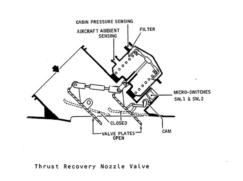
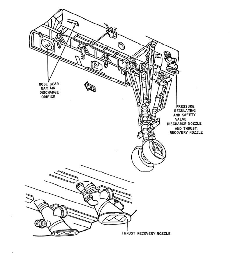
The Thrust recuperator (or thrust recovery nozzle) was fitted to the outlet of #1 (that is, left hand) forward discharge valve (outflow valve in Boeing speak) only. It was a variable 'louvre' type nozzle that would progressively close between 3 and 7.5 PSI diff'. The idea was to direct pressurisation outflow air directly backwards along (theoretically) the aircraft centre line (That at least was the theory). I read somewhere that at max diff' (10.7 PSIG) it would recuperate some 600 lb of thrust. HOWEVER, this system was fitted to the #1 system only (1 & 2 were used on alternate flights) and there was no performance penalty when the thing was not working. Here are a couple of diagrams.
Best Regards
Dude
Quote:
| , What does the function of the Thrust recuperator and how does it work? |
Best Regards
Dude
Last edited by M2dude; 23rd Dec 2010 at 10:42 . Reason: I stil kant sprell