21st Aug 2010, 16:11
permalink Post: 49
What I omitted to say about the Concorde FBW was that autostabilisation commands were superimposed onto the manual/autopilot demands directly at powered flying control unit (PFCU) level, on all 3 axis. . This made the aircraft superbly stable and precise to handle at almost any speed or condition. Apologies for IPhone again

Last edited by M2dude; 22nd Aug 2010 at 00:02 .
22nd Aug 2010, 12:29
permalink Post: 65
 Galaxy Flyer
Quote:
| One more question, could the Concorde lose pressurization, descend to some low level (FL180 or below, perhaps FL100) and make it to scheduled destination or would a divert to Shannon or Gander be required? What was a low level cruise speed? |
It's great that Bellerophon is posting here again; we need a steely eyed Concorde pilot's input here (not just the boffins/nutters and nerds [that's me
 ]. To touch more on a couple of his valid points;
Fuel burn: The aircraft would naturally require less fuel as she became lighter and as a consequence gently climbed to maintain cruise Mach number, this is what the engine control system was doing all the time, even though the throttles were wide open it was 'tweaking'.. BUT, the decreasing IAS as you climbed, due of course to the reducing density, just like any other aircraft meant that drag was reducing too, so it was a combination of both of these factors, reducing weight and reducing drag.
Flying controls: It was a slightly weird but wonderful arrangement; pilots inputs would move a servo valve in the hydraulic relay jack, the jack would move in response and drive both a resolver AND mechanical linkages. The resolver ourput was sumed with the flying control position resolvers, and the error signal was fed into an autostab' computer, where it was summed with stabilisation demands (primarily axis rate and acceleration). The autostab computer would the directly drive the surface, and the reducing error signal would reduce the demand etc. While all this was going on, the mechanical linkages would slavishly follow, but as long as you were in FBW (what we used to call 'signalling') mode, these mechanical inputs were de-clutched at the PFCU, so did nothing at all. Only if there was an EXTREMELY unlikely failure of BOTH FBW channels would these inputs be clutched in and the flying control group (rudders, inner elevons or outer and mid' elevons) would then be in Mechanical signalling. The system redundancy was checked after engine start on every flight. But to reinforce what Bellerophon stated, there was no mechanical reversion here; without hydraulics you had nothing. Another aside here; the designers, being paranoid like all good designers (no offence Christiaan
 ) were worried what would happen if the controls would somehow jam up. A jammed mechanical flying control input run itself would have no effect on FBW operation whatsoever, due to spring boxes being fitted to the runs. A 'Mech Jam' light would be set, together with a separate red light and audio warning, but this was all. But to completely protect against the aircraft was fitted with a Safety Flight Computer (SFC) system. The idea was, if a control axis (pitch or roll only) jammed up, the captain could press down on a switch light set between the two halves of his control wheel, (at the centre of the 'W') and the Emergency Flight Controls would activate. Strain gauges at the front of the control wheel, two sets on each control column for pitch and roll axis, would input into an SFC that would covert the control force into an elevon demand. These commands were then fed into the autostab' computers, and hence directly into the controls. (A little like L-1011 CWS in a way). There was a little test button that was used to test this system, again after engine start. So although the controls were jammed, the aircraft could still be flown. (Never used in anger I'm pleased to report).
But there was a problem; if this system was inadvertantly used, the results could have been catastrophic, as the system was extremely sensitive indeed, and full elevon movement could be enabled with only moderate effort. Because of this hairy prospect some safeguards were obviously put in place. The first safeguard was an interlock in the autostab' engage logic; If the switchlight had been inadvertently selected beforehand (the light was green by the way) you would not be able to engage pitch or roll autostab's (both channels too) so you would not be going flying until that was fixed. The second safeguard was a little more subtle; A plastic, frangible cover was fitted over the switchlight, unless the captain pressed reasonably hard the cover would prevent the switchlight from being pressed. At least that was the theory, in practice this little bit of plastic could be a pain in the ass
 . It was carefully fashioned, and I seem to remember BAe charging the airlines a few hundred pounds each for these things. If some wally fitted the cover upside down (and unless you were careful it was easy to do) THE THING WOULD NOT BREAK!! I remember at Fairford in 1976, G-BOAD was on pre-delivery flight testing, and the late great test pilot John Cochrane was doing a test of the system. The cover on this occasion HAD been fitted upside down, and of course he could not plunge his thumb through it and engage the EFC button. After trying everything, in the end he removed a shoe, took out his pen, and smashed the plastic cover until it broke. (It's OK, the autopilot was engaged at the time). Unfortunately, his combined shoe/pen emergency device also wrecked the switchlight as well, so the system still could not engage. (There was only a switchlight on the captain's side). After he landed and he confronted us all with his dilemma, he was shaking; not with rage but with laughter. (This was the great John Cochrane, sometimes the dour Scotsman but he was always able to see the lighter side). After that event, careful instructions were issued regarding the fit of the cover, and it was modified and made a little more frangible.
Last edited by M2dude; 23rd Aug 2010 at 00:02 . Reason: will engineers ever learn to spell?
23rd Aug 2010, 19:03
permalink Post: 86
Also, regarding the 4000psi pressure adopted - the control surfaces most definitely did need powerful actuators; as you now know they were very active, especially on approach and transonic, and as well as IASs of up to 530kts you have all the lever arm changes brought by shifting centres of pressure over the surfaces caused by shockwave movements.
If you want to fly supersonic, frontal area is everything so 4000psi also has the benefit of keeping the PFCU cross-section down.
I'm sure M2Dude will be able to give a better explanation of this aspect - it's nearly seven years since I flew the beast (that's depressing) and it's hard enough to remember detail of the flying bits, let alone the complex engineering aspects.
21st Sep 2010, 18:06
permalink Post: 443
For Mike_Bracknell
The rudder failures weren't really down to a fault with the original design, here's the story as I remember it:
The ctrl surfaces are made of a honeycomb-core bonded to the skins, essentially. They originally had a blunt trailing-edge, as was then de-rigeur with supersonic design. At some stage it was decided that a sharp trailing edge was actually beneficial so they had an extension fitted, which had the unfortunate effect of allowing a certain amount of water ingress to the core. Heating and expansion of this lead to disbonding and ultimately failure of the surfaces. (I suspect my engineering colleagues will have a much better and more accurate explanation).
Now - here's the important bit, and another example of this aeroplane's excellent failsafe engineering; Concorde had two rudders, one above the other (same as the 747). Each is driven by one dual-bodied PFCU. You ABSOLUTELY don't want a PFCU endangered by ctrl surface damage so each surface is divided in two, either side of the PFCU control horn.
Visualise the PFCU attached to the centre of two surfaces with an end rib on each, but skinned to look like one surface. Therefore, in the case of the surface suffering damage, it can only spread to a point short of the all-important PFCU. Look at the rudder-failure pictures and you'll see what I mean.
So - far from the 'rudder' breaking up, the reality is that half of one of the rudders had failed.
It was somewhat inevitable that Concorde's control sfcs would suffer, given the horrific loads they endured, and this was dealt with at the design stage. The elevons had the same sort of design.
It does of course look bad when you land with bits missing and this, plus the Regulators and company safety depts ensured that eventually some HUGELY expensive replacements were built.
25th Sep 2010, 22:03
permalink Post: 472
Chu Chu
,
You're quite right, actually, especially assuming no flow.
"how would the fluid in the "cylinder" "know" it's pressing against pressurized hydraulic fluid in the inner tube and not a solid steel piston? "
The fluid wouldn't "know".. It would be pressing against pressurized hydraulic fluid further down the line.... but at the end, it would finally be pressing against the piston of a hydraulic cylinder of some kind at the end, like the 'cap' in my first scribble.
If nothing was restrained "downstream", indeed everything would be "blown apart".
Of course, that hydraulic cylinder (my 'cap') would be affixed to the structure, so it wouldn't move.
The problem is more like my second scribble.... with a bend in the pipe, and only the final 'cap' fixed, the pipe would continuously flex under pressure.... not a good idea at all, especially when the pressure in the pipe varies, because the 'cap' is not a real 'cap' but something like a PFCU (power flight control unit), with continously varying demand.
So yes, the hydraulic lines are restrained in all the right places, for the hydraulic expansion seals to work correctly without setting up stresses in the lines themselves (except for the pressure acting outwards, of course).
Hope this makes sense to you?
CJ
16th Jan 2011, 06:52
permalink Post: 1109
Quote:
| How was the mechanical system 'de-coupled' from the electrical channels thus that any movement from the control column was 'ignored' by this channel ? |

In mechanical back-up control demands were fed to relay jacks which acted as force amplifiers so the pilot was unaware of control run friction. The autopilot also fed into these relay jacks. This meant that the control precision and ability to harmonise control forces given by the electrical control system was not degraded by mechanical system shortcomings.
In electrical signalling there was a dead space at the Powered Flying Control Units (PFCU) to allow for the difference between mechanical and electrical commands produced by autostabiliser activity. Variation of this dead space with flight condition gave the autostabiliser authority limits. Autostab. was not available in mechanical signalling when the PFCU servo valve was locked to the mechanical control system.
So the control column movements were never 'ignored' by either system, but the mechanical system never 'saw' the autostabiliser commands.
Cheers
Clive
16th Jan 2011, 09:41
permalink Post: 1110
SpeedbirdConcorde
Hi again my friend. To further expand on CliveJ's superb explanation: Mechanical control inputs were fed to each of the 8 Powerd Flying Control Units (PFCUs), but in electronic signalling (either Blue or Green) these inputs were de-clutched at the PFCU input lever. When Fly By Wire' signalling is not available, the mechanical inputs (which as CliveL quite rightly points out) are driven by the Relay Jacks, now are locked to the input lever and can now move the input jack of the PFCU (known as the spool valve) and subsequently cause the PFCU to drive the control surface. (The body of the PFCU moved, the main jacks were attached at each end to structure and so obviously did not move). Hopefully this diagram will help visualising the process a little easier:
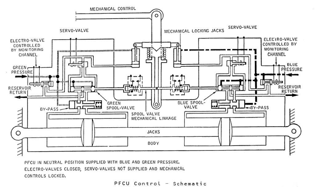
The diagram shows Green & Blue hydraulics supplied but the electro-valves (opened by the respective FBW channel) are both closed. You can see that the mechanical input lever is 'locked' to the PFCU input lever which will drive the SPOOL VALVE directly. When FBW is enabled, either the Blue or Green (never both together) ELECTRO-VALVE are signalled open, the ensuing hydraulic pressure then pushing the input clutch upwards and disengaging the mechanical input. FBW demands are now fed to the respective SERVO VALVE which will hydraulically send the SPOOL VALVE in the desired direction.
The Relay Jacks could be considered to be a little like a PFCU (you had 2 RJs per axix) but instead of the servo valves being driven by the FBW system they were driven by the autopilot and instead of driving a control surface, they drove the control runs. In manual flight the input spool was driven via a mechanical input lever, which would drive the RJ spool a little like Mech' signalling drove the PFCU spool. In A/P mode the mechanical input rod was de-clutched \xe0 la PFCU, but (and here's the clever part) this input was locked to the body of the Relay Jack which when it moved, drove the pilot's control in sympathy. (Control column, yoke or rudder pradals). As the respective control(s) was moved by the Relay Jack, the corresponding FBW position sensor (resolver) would change position and generate the FBW demand. (As the surface moved there was a feedback resolver at PFCU level).
As far as the FBW channels themselves went; there were 2 electronic signalling modes, Blue and Green, sub-divided into 3 groups (Inner Elevons, Outer & Mid Elevons and Rudders). Each group was independently monitored, and a fault in say the Rudder channel alone, would result in the rudders ONLY changing lanes. NOW ( ), The normal control channel was BLUE, and if this failed you would drop the respective channel into GREEN and if this failed you would drop into MECH. The selector switches (1 per group) enabled you to select BLUE/GREEN/MECH in that order. If for some reason you were selected to GREEN, a failure of that signalling lane would not drop you 'up' into BLUE, but into MECH. Your switch would only be in this position if you'd had a problem with BLUE, however you would select this on pushback while you were testing the flying controls, otherwise you spent your whole life selected to BLUE. As far as BA went, I can never remember a time personally when all 3 groups dropped from BLUE to MECH, but very rarely you might get a fault that caused a single group to briefly drop to MECH. Just about one of the very few common mode failures to each of the 3 groups would be a failure of the respective FBW static inverter. This thing, which was rightly monitored up to the hilt, produced a 26 Volt 1800 Hz output. (1800 Hz was chosen as this is not a harmonic of aircraft mainline 400 Hz AC supply)
Best regards
Dude
Hi again my friend. To further expand on CliveJ's superb explanation: Mechanical control inputs were fed to each of the 8 Powerd Flying Control Units (PFCUs), but in electronic signalling (either Blue or Green) these inputs were de-clutched at the PFCU input lever. When Fly By Wire' signalling is not available, the mechanical inputs (which as CliveL quite rightly points out) are driven by the Relay Jacks, now are locked to the input lever and can now move the input jack of the PFCU (known as the spool valve) and subsequently cause the PFCU to drive the control surface. (The body of the PFCU moved, the main jacks were attached at each end to structure and so obviously did not move). Hopefully this diagram will help visualising the process a little easier:
The diagram shows Green & Blue hydraulics supplied but the electro-valves (opened by the respective FBW channel) are both closed. You can see that the mechanical input lever is 'locked' to the PFCU input lever which will drive the SPOOL VALVE directly. When FBW is enabled, either the Blue or Green (never both together) ELECTRO-VALVE are signalled open, the ensuing hydraulic pressure then pushing the input clutch upwards and disengaging the mechanical input. FBW demands are now fed to the respective SERVO VALVE which will hydraulically send the SPOOL VALVE in the desired direction.
The Relay Jacks could be considered to be a little like a PFCU (you had 2 RJs per axix) but instead of the servo valves being driven by the FBW system they were driven by the autopilot and instead of driving a control surface, they drove the control runs. In manual flight the input spool was driven via a mechanical input lever, which would drive the RJ spool a little like Mech' signalling drove the PFCU spool. In A/P mode the mechanical input rod was de-clutched \xe0 la PFCU, but (and here's the clever part) this input was locked to the body of the Relay Jack which when it moved, drove the pilot's control in sympathy. (Control column, yoke or rudder pradals). As the respective control(s) was moved by the Relay Jack, the corresponding FBW position sensor (resolver) would change position and generate the FBW demand. (As the surface moved there was a feedback resolver at PFCU level).
As far as the FBW channels themselves went; there were 2 electronic signalling modes, Blue and Green, sub-divided into 3 groups (Inner Elevons, Outer & Mid Elevons and Rudders). Each group was independently monitored, and a fault in say the Rudder channel alone, would result in the rudders ONLY changing lanes. NOW ( ), The normal control channel was BLUE, and if this failed you would drop the respective channel into GREEN and if this failed you would drop into MECH. The selector switches (1 per group) enabled you to select BLUE/GREEN/MECH in that order. If for some reason you were selected to GREEN, a failure of that signalling lane would not drop you 'up' into BLUE, but into MECH. Your switch would only be in this position if you'd had a problem with BLUE, however you would select this on pushback while you were testing the flying controls, otherwise you spent your whole life selected to BLUE. As far as BA went, I can never remember a time personally when all 3 groups dropped from BLUE to MECH, but very rarely you might get a fault that caused a single group to briefly drop to MECH. Just about one of the very few common mode failures to each of the 3 groups would be a failure of the respective FBW static inverter. This thing, which was rightly monitored up to the hilt, produced a 26 Volt 1800 Hz output. (1800 Hz was chosen as this is not a harmonic of aircraft mainline 400 Hz AC supply)
Best regards
Dude
Last edited by M2dude; 16th Jan 2011 at 12:10 . Reason: Clarity; Oh for clarity
21st Jun 2011, 15:45
permalink Post: 1388
A Side Sticky Subject
As I recall, they referred to this research project as a CCV (Controlled Configured Vehicle) design study. It would be great if we could get this confirmed, but they talked about subsonic drag reductions of 10 to 15% by flying (not taking off!!) with a far more aft CG than the norm. The 'system' I seem to remember, as a result naturally commanded some down elevon, which increased lift. As the aircraft could then fly with less alpha, I guess this is where the drag reduction comes from. (Clive, I wonder if you could find out through one of your contacts if this was true?).
I'd still personally like to know how the sidestick was integrated into the flying control system, I've been thinking and can not now believe that sidestick inputs could be simply input to the flying control system 'at resolver level'. Remember that the concept of the FBW system on Concorde was that resolvers were utilised as simple 4 wire synchros, and the pitch and roll axis utilised a CX/CDX/CT chain, which produced the error signal to the ESA's in the Autostab computers. Using a sidestick completely breaks up the chain, and my guess is that a seperate digital unit contained the flight rules which were summed against PFCU CT position and sidestick input would have been necessary. It is possible then that an analog output from this 'box' could be fed to the Autostab Computer ESAs and hence drive the elevons. I'm probably completely wrong, but I'd surely still love to know the truth. As you say Clive, ideal stuff for Concorde 2.
Best regards
Dude
Last edited by M2dude; 21st Jun 2011 at 18:53 . Reason: A fine wine may improve with age... my spelling however doesn't
7th Dec 2013, 09:17
permalink Post: 1765
EXWOK ...well it was some time ago and my memory may not be what it was...
Anyway, PPRuNe was not around then so the only rumour network speculating about such events was the local newspaper and the comments about the wind have stuck in my memory.
I wouldn't dismiss the Canterbury surface winds too lightly - they can and have caused a lot of damage especially to property and trees. Sitting in a 737 in a Nor'wester at Harewood at departure time can be a shaky experience.
However, I take your point about back driving a PFCU. Thinking about it, I would doubt that ground wind forces would come anywhere near the forces experienced in supersonic flight