22nd Aug 2010, 12:29
permalink Post: 65
 Galaxy Flyer
Quote:
| One more question, could the Concorde lose pressurization, descend to some low level (FL180 or below, perhaps FL100) and make it to scheduled destination or would a divert to Shannon or Gander be required? What was a low level cruise speed? |
It's great that Bellerophon is posting here again; we need a steely eyed Concorde pilot's input here (not just the boffins/nutters and nerds [that's me
 ]. To touch more on a couple of his valid points;
Fuel burn: The aircraft would naturally require less fuel as she became lighter and as a consequence gently climbed to maintain cruise Mach number, this is what the engine control system was doing all the time, even though the throttles were wide open it was 'tweaking'.. BUT, the decreasing IAS as you climbed, due of course to the reducing density, just like any other aircraft meant that drag was reducing too, so it was a combination of both of these factors, reducing weight and reducing drag.
Flying controls: It was a slightly weird but wonderful arrangement; pilots inputs would move a servo valve in the hydraulic relay jack, the jack would move in response and drive both a resolver AND mechanical linkages. The resolver ourput was sumed with the flying control position resolvers, and the error signal was fed into an autostab' computer, where it was summed with stabilisation demands (primarily axis rate and acceleration). The autostab computer would the directly drive the surface, and the reducing error signal would reduce the demand etc. While all this was going on, the mechanical linkages would slavishly follow, but as long as you were in FBW (what we used to call 'signalling') mode, these mechanical inputs were de-clutched at the PFCU, so did nothing at all. Only if there was an EXTREMELY unlikely failure of BOTH FBW channels would these inputs be clutched in and the flying control group (rudders, inner elevons or outer and mid' elevons) would then be in Mechanical signalling. The system redundancy was checked after engine start on every flight. But to reinforce what Bellerophon stated, there was no mechanical reversion here; without hydraulics you had nothing. Another aside here; the designers, being paranoid like all good designers (no offence Christiaan
 ) were worried what would happen if the controls would somehow jam up. A jammed mechanical flying control input run itself would have no effect on FBW operation whatsoever, due to spring boxes being fitted to the runs. A 'Mech Jam' light would be set, together with a separate red light and audio warning, but this was all. But to completely protect against the aircraft was fitted with a Safety Flight Computer (SFC) system. The idea was, if a control axis (pitch or roll only) jammed up, the captain could press down on a switch light set between the two halves of his control wheel, (at the centre of the 'W') and the Emergency Flight Controls would activate. Strain gauges at the front of the control wheel, two sets on each control column for pitch and roll axis, would input into an SFC that would covert the control force into an elevon demand. These commands were then fed into the autostab' computers, and hence directly into the controls. (A little like L-1011 CWS in a way). There was a little test button that was used to test this system, again after engine start. So although the controls were jammed, the aircraft could still be flown. (Never used in anger I'm pleased to report).
But there was a problem; if this system was inadvertantly used, the results could have been catastrophic, as the system was extremely sensitive indeed, and full elevon movement could be enabled with only moderate effort. Because of this hairy prospect some safeguards were obviously put in place. The first safeguard was an interlock in the autostab' engage logic; If the switchlight had been inadvertently selected beforehand (the light was green by the way) you would not be able to engage pitch or roll autostab's (both channels too) so you would not be going flying until that was fixed. The second safeguard was a little more subtle; A plastic, frangible cover was fitted over the switchlight, unless the captain pressed reasonably hard the cover would prevent the switchlight from being pressed. At least that was the theory, in practice this little bit of plastic could be a pain in the ass
 . It was carefully fashioned, and I seem to remember BAe charging the airlines a few hundred pounds each for these things. If some wally fitted the cover upside down (and unless you were careful it was easy to do) THE THING WOULD NOT BREAK!! I remember at Fairford in 1976, G-BOAD was on pre-delivery flight testing, and the late great test pilot John Cochrane was doing a test of the system. The cover on this occasion HAD been fitted upside down, and of course he could not plunge his thumb through it and engage the EFC button. After trying everything, in the end he removed a shoe, took out his pen, and smashed the plastic cover until it broke. (It's OK, the autopilot was engaged at the time). Unfortunately, his combined shoe/pen emergency device also wrecked the switchlight as well, so the system still could not engage. (There was only a switchlight on the captain's side). After he landed and he confronted us all with his dilemma, he was shaking; not with rage but with laughter. (This was the great John Cochrane, sometimes the dour Scotsman but he was always able to see the lighter side). After that event, careful instructions were issued regarding the fit of the cover, and it was modified and made a little more frangible.
Last edited by M2dude; 23rd Aug 2010 at 00:02 . Reason: will engineers ever learn to spell?
25th Aug 2010, 14:39
permalink Post: 111
I have been been on PPRuNe for 10 years now, and this is one of the most fascinating threads I've ever read. Some of the quotes give me goosebumps:
And to think that she was designed in the 1960s by men with slide rules and drawing boards. How fitting that the most sophisticated airliner ever built was also by far and away the most beautiful.
Some years ago I had the privilege of meeting Capt. David Rowland (he of the ITVV video fame) at a GAPAN aptitude test day, and it is one of my cherished memories. I recall we spent about 30 seconds discussing my test results, and the remaining 10 minutes chatting about Concorde . . .
Please keep the memories coming guys \x96 as a humble Dash 8 driver, I will always be in awe of the technological marvel which was Concorde.
Quote:
| this fuel system really was a study in elegance. |
Quote:
| On test flights however, the aircraft would routinely zoom climb to FL 630 . . . . . . the highest recorded Concorde altitude was on one of the French development aircraft, which achieved 68,000'. |
Quote:
| The powerplant was as you say truly amazing. We had an, as yet, unmatched engine/intake combination, with a variable primary and secondary nozzles. The variable intake allowed supersonic operation with maximum pressure recovery, minimum aerodynamic drag, as well as extreme operational stability. (Extreme temperature shears, that would have caused surge/unstarts in military installations) were dealt with as a total non event). It's astonishing to believe, but at Mach 2 cruise, the intake provided approximately 63% of the powerplant thrust. It was controlled by the world's first airborne digital control system. |
Quote:
| We never had a case of lost pressurisation, ever. |
Quote:
| the aircraft handled beautifully through an 1100kt speed range. |
Some years ago I had the privilege of meeting Capt. David Rowland (he of the ITVV video fame) at a GAPAN aptitude test day, and it is one of my cherished memories. I recall we spent about 30 seconds discussing my test results, and the remaining 10 minutes chatting about Concorde . . .
Please keep the memories coming guys \x96 as a humble Dash 8 driver, I will always be in awe of the technological marvel which was Concorde.
30th Sep 2010, 13:58
permalink Post: 499
As promised here are the answers to our trivia quiz.
Actually there were 14 (but if you are not necessarily a Concorde person, 13 is acceptable). There were '13 fuel tanks, numbered 1 - 11' as we used to tell all the visitors to the aircraft, (The wingtip tanks 5A & 7A making up the extra 2) PLUS a single small
scavenge tank
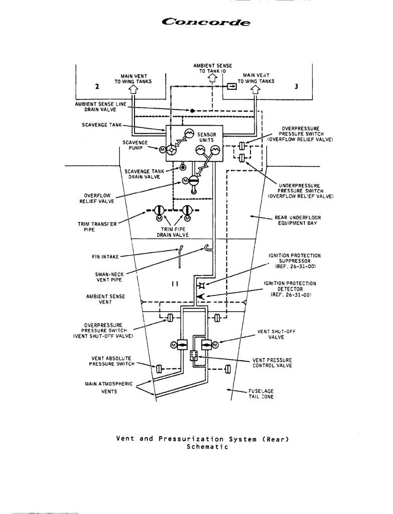
at the rear of the aircraft that was used to remove fuel from the vent lines and return this fuel via a transfer pump back to tank 3. (A fuel level sensor would trigger the pump with only 1 US Gallon of fuel in the tank). If the trim gallery became over-pressurised (ie tank 3 already full to the brim) an overflow relief valve (ORV) underneath the rear of the aircraft would open and dump the contents of the tank overboard. There was a flight deck indication if the scavenge pump was running in flight to give the crew an indication that a tank somewhere was probably over-filling and to take the appropriate action. There was one added goody about the ORV; If you were on the ground with the refuel door open and due to a refuelling overfill anywhere, fuel entered the scavenge tank, at 7 gallons the ORV would open and rapidly dump the fuel on the floor. For this reason a vent pipe and fuel drum was often placed underneath the ORV during high load refuels. If this was not fitted and you just happened to walk underneath the aircraft at the wrong moment during fuelling........

As a total aside to all this (or me going off on a tangent yet again) the fuel tanks themselves were gently air pressurised above 44,000' to around 2.2 PSIA. This was to prevent the beginnings of any boiling of the fuel in the tanks, due to the low ambient pressure/high fuel temperatures, causing pump cavitation. (Boiling itself could not occur much below 65,000'). A small NACA duct at the right side of the fin was used to supply the ram air for tank pressurisation, the two vent valves in the tail cone, one per trim gallery, closing off automatically at around 44,000', the pressure being controlled by a pneumatic valve, with full automatic over-pressure protection. OK sorry guys and gals, back to the answers:
This is the stinker.... there were 114 (although at entry into service there were 115!!). 100 passenger seats + 6 cabin crew seats + 5 flight deck seats (including the fold up seat in the aisle at the rear) PLUS 3 LOO SEATS (Originally 4 loos, the fourth loo being removed in the early 1980's).

50,189' and 530 KEAS, but we'll settle for anything around FL500 being correct.

Aircraft 216, G-BOAF, the last Concorde ever built. When 216 first flew in 1979 she was a variant 192 'British Unsold Aircraft' and was registered as G-BFKX. In late 1979, BA purchased the aircraft and it was subsequently converted to a Type 102 British Airways variant, and after modifications were complete, test flights were carried out from Filton under the registration of G-N94AF. This registration was to enable the aircraft to participate in the Braniff interchange between IAD and DFW, but when the Braniff Concorde adventure unfortunately ended in 1980, she was again re-registered to G-BOAF, this is how she was delivered to BA later that year.
Easy one this I hope; 60.000'. (As we've said before this limitation was imposed because of the dual window failure / emergency descent time consideration, not as a performance issue. On test flights 63,000' was routinely attained, and altitudes of up to 68,000' were achieved during development flying. (On her maiden flight, G-BOAB achieved 65,000' and Mach 2.04; the first British constructed Concorde to achieve Mach 2 on her maiden flight, and the ONLY one of the original five BA aircraft to achieve this).
Hopefully an easy one... there were TWELVE: 2 nose wheels, 8 main wheels and 2 tail wheels. (No, even I'm not nasty enough to include the wheels on the bar trolleys
). Oh, and there were 9 wheel brakes, one for each main wheel and as was mentioned in a previous post, a single steel disc brake for the nose wheels (the nose having a live axle), for automatic use during gear retraction only.

Three modes; Blue electronic signalling, green electronic signalling and mechanical signalling. I suppose we COULD be pedantic here and include the Emergency Flight Control mode where even with a jammed control column/control wheel, strain gauges (and Safety Flight Control Computers of course) would still enable you to control the elevons.
OK, three basically. Up (Duh!), 5 degrees for taxi/take off and low speed flight and 12.5 degrees for landing. As ChristiaanJ quite rightly pointed out in an earlier post, the prototype (and pre-production) aircraft landing position was 17.5 degrees of droop. (In my view the nose of the aircraft looked a little like an armadillo in this extreme configuration).

In 1977 the new digital Plessey PVS 1580 Aircraft Integrated Data System was progressively fitted to the BA fleet, this being the first microprocessor application on Concorde, this application being followed in several other systems during the life of the aircraft. The 'final' applications being TCAS and the superb retrofitted Bendix RDR-4A weather radar system.

No we are not including torch batteries and emergency lights etc.
There were a total of seven main power sources: 4 x 60KVA AC generators, one per engine, a single 40KVA hydraulically powered emergency generator and 2 lead acid (or ni-cad in the case of G-BOAG) main aircraft batteries. (Not a terribly Re-Volting question I hope).

I hope this quiz was fun and not too perplexing to any of you guys.
Dude
Quote:
| 1) How many fuel tanks were there on Concorde? |
As a total aside to all this (or me going off on a tangent yet again) the fuel tanks themselves were gently air pressurised above 44,000' to around 2.2 PSIA. This was to prevent the beginnings of any boiling of the fuel in the tanks, due to the low ambient pressure/high fuel temperatures, causing pump cavitation. (Boiling itself could not occur much below 65,000'). A small NACA duct at the right side of the fin was used to supply the ram air for tank pressurisation, the two vent valves in the tail cone, one per trim gallery, closing off automatically at around 44,000', the pressure being controlled by a pneumatic valve, with full automatic over-pressure protection. OK sorry guys and gals, back to the answers:
Quote:
| 2) How many seats were there? |
Quote:
| 3) At what approximate altitude and KNOTS EAS was Mach 2 achieved? |
Quote:
| 4) Only one BA Concorde had three different registrations, what was it? |
Quote:
| 5) What was the maximum permitted altitude in passenger service? |
Quote:
| 6) How many wheels on the aircraft |
). Oh, and there were 9 wheel brakes, one for each main wheel and as was mentioned in a previous post, a single steel disc brake for the nose wheels (the nose having a live axle), for automatic use during gear retraction only.
Quote:
| 7) How many flying control modes were there? |
Quote:
| 8) How many positions of nose droop were there? |
Quote:
| 9) What was the first microprocessor application on the aircraft? |
Quote:
| 10) How many main electrical sources were there? |
There were a total of seven main power sources: 4 x 60KVA AC generators, one per engine, a single 40KVA hydraulically powered emergency generator and 2 lead acid (or ni-cad in the case of G-BOAG) main aircraft batteries. (Not a terribly Re-Volting question I hope).
I hope this quiz was fun and not too perplexing to any of you guys.
Dude
26th Nov 2010, 08:47
permalink Post: 781
speedbirdconcorde
Yes we did, just a couple if I remember correctly and relatively minor failures at that. (Regular ultrasonic NDT inspections had been instigated to pre-empt these failures from actually occuring). New elevon purchases were rightly seen to be the answer to the problem; the poorly designed trailing edge extension modifications of the late 1970's were as was said before, the source of these failures, due to moisture ingress in the honeycombe structure).
Mr Vortex
As has been posted previously, there was a small NACA duct on the right hand side of the fin, that provided the air source for fuel tank pressurisation. This pressure was controlled to 1.5 PSIG.
This switch operated two valves that would drain out any residual fuel for maintenance (for example, replacing a vent valve); it was not used very often however.
Islander539 and ChristiaanJ
The actions of Airbus at Filton are nothing short of disgusting. By 'removing the insulation' you will need to strip the cabin completely bare (seats, galleys, ceiling panels and all of the side-wall panels). They say that 'Filton was only ever going to be an interim home for Concorde', what total
crap
!!
The idea is to 'cocoon' the aircraft 'until a permanent home is found'. I hope all readers here realise that this will involve BREAKING UP THE AIRFRAME to make it road transportable. The reasons that scarebus are giving for all this are vague and misleading, but here's my take. There are pressures around from various people and bodies 'to return a British Concorde to flying condition.' Now a lot (NOT ALL) of these people although very well intentioned are not that well informed and their wishes are not reasonably possible. But the pressures exist nonetheless, and scarebus will do anything to prevent this possibility, nomatter how unlikely, from being progressed. So we have G-BOAF, the youngest Concorde in the world, with the lowest airframe hours, in pretty good structural condition (she's suffered from being outside for 7 years, but nothing terminal) and actually in the hands of the dreaded scarebus (who would rather forget that Concorde ever existed, and was almost certainly the reason why they even noe exist). Doesn't take much working out now, does it?
Dude
Quote:
Regarding the rather important role of the elevons on Concorde
 where there any failures during her time in the skies ?
|
Mr Vortex
Quote:
|
I've just wonder that does the Concorde use a surge tank or
some a kind of a NACA duct like on B737 for pressurize the fuel in a tank? |
Quote:
Also, in Concorde F/E panel around the fuel control panel there're switch call trim pipe drain switch. Which I tried to read and figure it out but finally I don't know what it actually do
 and in which circumstance do we need to use it
|
Islander539 and ChristiaanJ
The actions of Airbus at Filton are nothing short of disgusting. By 'removing the insulation' you will need to strip the cabin completely bare (seats, galleys, ceiling panels and all of the side-wall panels). They say that 'Filton was only ever going to be an interim home for Concorde', what total
crap
!!
The idea is to 'cocoon' the aircraft 'until a permanent home is found'. I hope all readers here realise that this will involve BREAKING UP THE AIRFRAME to make it road transportable. The reasons that scarebus are giving for all this are vague and misleading, but here's my take. There are pressures around from various people and bodies 'to return a British Concorde to flying condition.' Now a lot (NOT ALL) of these people although very well intentioned are not that well informed and their wishes are not reasonably possible. But the pressures exist nonetheless, and scarebus will do anything to prevent this possibility, nomatter how unlikely, from being progressed. So we have G-BOAF, the youngest Concorde in the world, with the lowest airframe hours, in pretty good structural condition (she's suffered from being outside for 7 years, but nothing terminal) and actually in the hands of the dreaded scarebus (who would rather forget that Concorde ever existed, and was almost certainly the reason why they even noe exist). Doesn't take much working out now, does it?
Dude
1st Dec 2010, 11:32
permalink Post: 821
Fuel tank vent and pressurisation
Mr Vortex
Finally as promised, here is a schematic of the AFT part of the fuel vent system. As you can tsee the fin intake pressurises the air space above tank 11, and hence, via the Scavenge Tank air-space, the remaining tanks. (Also you can see the Trim Pipe Drain Vaves you were asking about.
Regards Dude
Quote:
Finally, does some one have a schematic or the fuel vent system?

|
Regards Dude
23rd Dec 2010, 09:21
permalink Post: 963
Mr Vortex
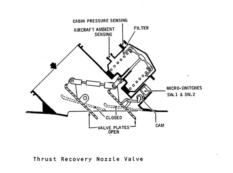
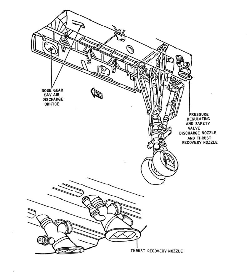
The Thrust recuperator (or thrust recovery nozzle) was fitted to the outlet of #1 (that is, left hand) forward discharge valve (outflow valve in Boeing speak) only. It was a variable 'louvre' type nozzle that would progressively close between 3 and 7.5 PSI diff'. The idea was to direct pressurisation outflow air directly backwards along (theoretically) the aircraft centre line (That at least was the theory). I read somewhere that at max diff' (10.7 PSIG) it would recuperate some 600 lb of thrust. HOWEVER, this system was fitted to the #1 system only (1 & 2 were used on alternate flights) and there was no performance penalty when the thing was not working. Here are a couple of diagrams.
Best Regards
Dude
Quote:
| , What does the function of the Thrust recuperator and how does it work? |
Best Regards
Dude
Last edited by M2dude; 23rd Dec 2010 at 10:42 . Reason: I stil kant sprell
24th Dec 2010, 11:34
permalink Post: 983
CliveL
The dual pressurisation systems each had two discharge valves, one just aft of the nose undercarriage and the other at the rear of the aircraft. The forward valves would carry away the electronics rack discharge air, where the aft would vent the underfloor area. There was no common discharge point Clive, no. The #2 system forward valve would just throw the air overboard, without the sophisticated 'nozzling' of the #1 system. So I guess we have to go figure just how useful the thrust recuperation system was, but I personally think that EXWOK got it right.
ChristiaanJ
The stiffenersd did not go over the bathtub joints my friend, , they were inboard.
Mike-Bracknell
Unfortunately Mike your photo is a little too far outboard to show them. We need to go a little more inboard and slightly further aft. I've been through my photos and can't yet find one. (Honest CliveJ, it is the truth, they DO exist
).
A very happy Christmas to everyone here; Personally I am working right through Christmas AND New Year (darned aeroplanes)
Dude
Quote:
|
Dude, Do you know how the #2 system was exhausted if it wasn't through another thrust recovery nozzle? We were never going to throw away 600 lbf thrust every other flight - not on Concorde where we sweated blood to get the parasitic drag down!
Any chance that there was a common discharge point even if the two packs were used alternately? |
ChristiaanJ
Quote:
|
Any chance of a pic or a drawing, M2dude?
It seems almost impossible to me that it was 'something' between inner and outer wing, since it would have had to 'jump' over the bathtub covers. |
Mike-Bracknell
Quote:
| Since a picture's worth a thousand words, if you guys would like to point to the strengthening straps/spars/thingies on this? |
).
A very happy Christmas to everyone here; Personally I am working right through Christmas AND New Year (darned aeroplanes)
Dude
15th Jan 2011, 08:20
permalink Post: 1098
Shaggy Sheep Driver
I personally agree about that photo, YUCH!!
Now about the cabin pressure thing: The pressurisation system would control to a MAXIMUM differential of 10.7 PSIG. Now at 60,000' the static pressure is 1.04 PSIA and at that altitude we would not QUITE be able to hold a cabin altitude of 6000', more like 6,200-6,300'. This is because 6000' altitude corresponds to a static pressure of 11.78 PSIA, giving us a diff' of 10.76 PSIG. Still as near as dammit mind, and for the MAJORITY of Atlantic crossings 6000' was fine. Such a 'civilised' cabin pressure was just one of the 1000 reasons that you never 'felt' as if you'd just flown over 3000 miles in Concorde.
Here is a diagram of the pressurisation panel.
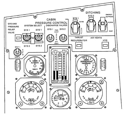
The idea was that you selected a desired cabin altitude and the system would control to maintain that altitude all the way up to max diff. You could control the rate of presurisation too, to minimise popping ears etc. (Personally I always found Concorde particualarly good in that respect). There is one minor goof in the diagram, in that the discharge valve position indicator show both systems in operation. You only ever had one of the two systems in operation (via the SYS1/SYS2 selector switches). The only exception to this was on the ground when both systems were powered (and both sets of valves fully open).
Best regards
Dude
I personally agree about that photo, YUCH!!
Now about the cabin pressure thing: The pressurisation system would control to a MAXIMUM differential of 10.7 PSIG. Now at 60,000' the static pressure is 1.04 PSIA and at that altitude we would not QUITE be able to hold a cabin altitude of 6000', more like 6,200-6,300'. This is because 6000' altitude corresponds to a static pressure of 11.78 PSIA, giving us a diff' of 10.76 PSIG. Still as near as dammit mind, and for the MAJORITY of Atlantic crossings 6000' was fine. Such a 'civilised' cabin pressure was just one of the 1000 reasons that you never 'felt' as if you'd just flown over 3000 miles in Concorde.
Here is a diagram of the pressurisation panel.
The idea was that you selected a desired cabin altitude and the system would control to maintain that altitude all the way up to max diff. You could control the rate of presurisation too, to minimise popping ears etc. (Personally I always found Concorde particualarly good in that respect). There is one minor goof in the diagram, in that the discharge valve position indicator show both systems in operation. You only ever had one of the two systems in operation (via the SYS1/SYS2 selector switches). The only exception to this was on the ground when both systems were powered (and both sets of valves fully open).
Best regards
Dude
Last edited by M2dude; 15th Jan 2011 at 08:31 . Reason: kerrektions
8th Apr 2011, 18:33
permalink Post: 1285
Fatigue
I saw some questions earlier about performance but that's pretty well documented. I was wondering more about for how much longer ( if there had been no retirement )??
Was there a Fatigue Index as other aircraft of the same era \x96 I only know of the Tornado in this respect: a long calculation was made per flight taken of flight duration, G readings, TO weight, Landing weight etc leaving a small number of 0.0000x per flight. Then added to the current FI to give a forecast of life left. If anyone remembers the Tornado 25FI Update Program debacle in the 90's ???
So how was the Concorde's airframe life calculated ?? Flying hours or perhaps pressurisation cycles ? Did a higher altitude effect anything since there would be a higher differential pressure??
On the Engine side, I remember an Olympus Service Bulletin describing the calculation of Fatigue Cycles for the Oly 200:- There was a calculation with several parameters but instruction to disregard below a certain figure, 85% to Max RPM & back was a regarded as a cycle and the LP Turbine Disc was the component with the lowest number of cycles before the need for overhaul.Was this still the case with the 593 ??
8th Apr 2011, 19:07
permalink Post: 1286
Quote:
| So how was the Concorde's airframe life calculated ?? Flying hours or perhaps pressurisation cycles ? Did a higher altitude effect anything since there would be a higher differential pressure?? |
Not so bad as it sounds in calendar years, as the annual utilisation of any one aircraft was very low, and there would also have been scope for life extension by applying certain modifications to the fuselage.
18th Oct 2013, 19:12
permalink Post: 1734
Dozy
Yeah, well when we put a digital computer to generate the AICS laws that was NEW man!
Again, no digital multifunction displays on offer in those days
Errrr no, I don't think so. Concorde's flight deck was done at Filton and we had no involvement in the Airbus designs in that area.
Exwok's remark is not quite right IIRC. Certainly the window size was dictated by pressurisation failure, but one couldn't maintain cabin pressure with two windows failed - the design case was to get to a breathable altitude before you killed too many passengers! Also, there is very little to see when you have a delta wing under you.
Ummm - most participants reckoned that the Concorde infrastructure showed the way not to do it, and besides the early Airbuses were developed in parallel with the later stages of Concorde development. You have a point where R&D is concerned though - several technologies developed for Concorde found their way onto the subsonic fleet, not the least being the probability approach to system certification.
Quote:
| Even when Concorde entered production, the most complex digital displays available to aviation were of the 7-segment LED type (as used in the Apollo Guidance Computer), and they were both wildly expensive and of limited use. |
Quote:
| Ergonomically speaking, both engineers and pilots of the era write of Concorde's flight deck being the best possible balance of form and function available at the time - sure it looks cluttered to the modern eye, |
Quote:
| It's worth bearing in mind that even those not particularly well-disposed to Airbus will grudgingly admit that the flight deck ergonomics on those types are extremely good - and a lot of the lessons learned were from cramming all that information into Concorde's limited space. |
Quote:
| I have to thank EXWOK for explaining the windows - but I'll add the more prosaic reason that you don't need a particularly large window to see the curvature of the Earth in all its splendour - which is for the most part all you'd be seeing during the flight! |
Quote:
| While Concorde herself never recouped the development money granted by the governments of the UK and France, the infrastructure and R&D her development put in place paved the way for the Airbus project |
22nd Feb 2014, 01:48
permalink Post: 1788
Shaggy Sheep Driver
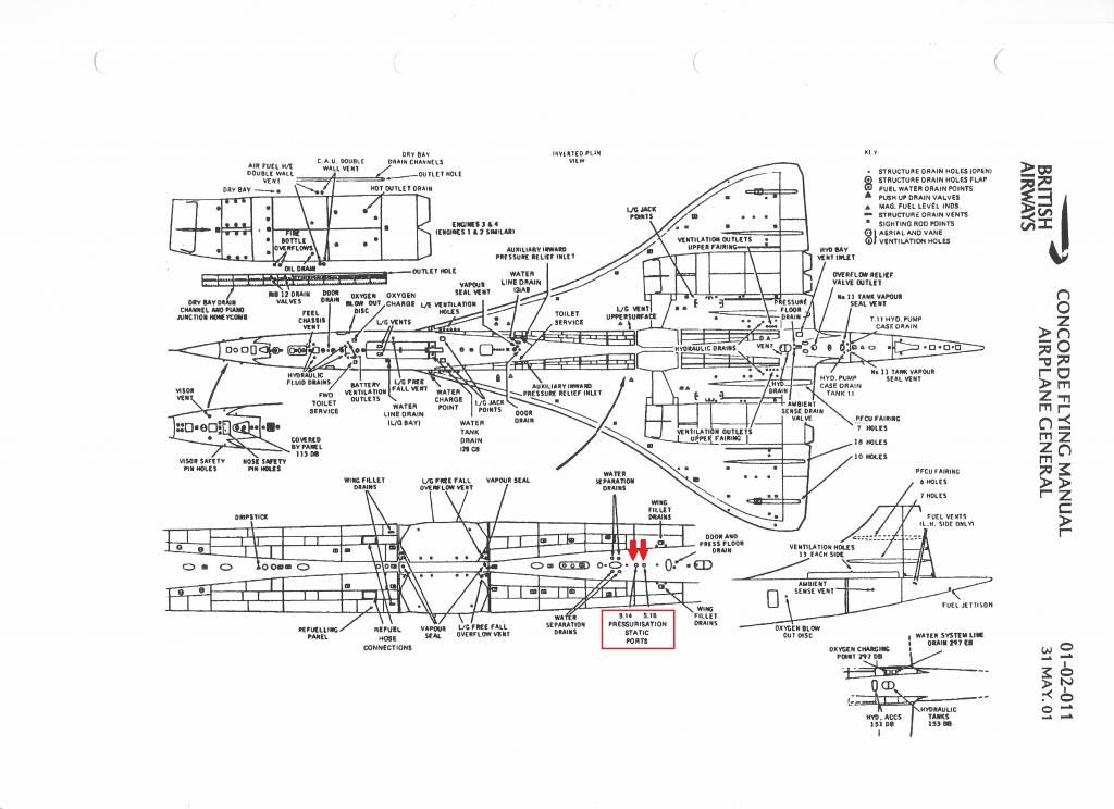
...I've noticed static ports under the fuselage at the back, between the engines. Are these just additional ports for the aircraft's general static pressure measurement system, or do they have a specific function?...
I'm not the right person to be answering this, and the reference diagram I'm looking at, whilst very detailed, is not particularly clear - at least to a pilot!
However, from your description, I wonder if they might possibly be the two pressurisation static ports that are located in that area?
22nd Feb 2014, 12:30
permalink Post: 1792
Shaggy Sheep Driver
S14 and S15 decode as "Pressurisation Static Ports".
Anything more than that and I'm afraid I'm out of my depth, so you'll need one of our resident engineer experts to chip in. The one I'm thinking of might be at sea at the moment!
Here's the page from the Flying Manual:
Concorde Static Ports S14 and S15
23rd Feb 2014, 21:29
permalink Post: 1796
Many thanks Bellerophon and others. It seems these ports are concerned with cabin pressurisation.