18th Jan 2011, 06:28
permalink Post: 1118
Good to have you back here again Howie

There was no automatic ignition selection logic as such built into the start sequence, but a manually selected L & R ignition selector switch. The reason of course to alternate L & R selection during starting was to detect otherwise dormant ignition failures if 'BOTH' was always selected. (Modern A/C with AUTOSTART do not have this problem, if an ignitor fails during the engine start sequence the other is automatically selected and an ignition status message is set on the lower EICAS screen). The ignition L/R selector switch was bypassed during engine operation by the auto-ignition system, where if the engine control unit detected a flame out (set at 58% N2) both ignitors would automatically fire up. The sequence would release onece the perceived N2 rose above 63%. The ignition system had several reliability issues, the first was the plugs themselves. Penetration into the 'can' was crucial; if it were more than about 130 thou', the tip would very quickly burn off. We soon learned that a penetration check was vital when fitting a plug and shims needed to be used to get the correct penetration. The other reliability issue was the ignition leads themselves; For the first 10 years of service they were a major pain until 'they' (Rolls-Royce) finally got it right. Also until Rolls modified the lead clipping, it could take 3 to 4 HOURS to change a lead. The dual channel HEIU itself was as good as gold, and seldom let us down, It was a very powerful 8 Joule 2KV beast, and you obviously treated it with utmost respect.
Best regards
Dude
Quote:
| Really alternate side Ignitors? All RR aero engines I have worked on always sparked up both sides every time, well the Avon, Spey 202, RB199 & the Oly 20202 (Vulcan) and industrial Oly did. Would this have made a difficulty with starting logic?? Was there LH & RH Ignition selector switch maybe? |
There was no automatic ignition selection logic as such built into the start sequence, but a manually selected L & R ignition selector switch. The reason of course to alternate L & R selection during starting was to detect otherwise dormant ignition failures if 'BOTH' was always selected. (Modern A/C with AUTOSTART do not have this problem, if an ignitor fails during the engine start sequence the other is automatically selected and an ignition status message is set on the lower EICAS screen). The ignition L/R selector switch was bypassed during engine operation by the auto-ignition system, where if the engine control unit detected a flame out (set at 58% N2) both ignitors would automatically fire up. The sequence would release onece the perceived N2 rose above 63%. The ignition system had several reliability issues, the first was the plugs themselves. Penetration into the 'can' was crucial; if it were more than about 130 thou', the tip would very quickly burn off. We soon learned that a penetration check was vital when fitting a plug and shims needed to be used to get the correct penetration. The other reliability issue was the ignition leads themselves; For the first 10 years of service they were a major pain until 'they' (Rolls-Royce) finally got it right. Also until Rolls modified the lead clipping, it could take 3 to 4 HOURS to change a lead. The dual channel HEIU itself was as good as gold, and seldom let us down, It was a very powerful 8 Joule 2KV beast, and you obviously treated it with utmost respect.
Best regards
Dude
Last edited by M2dude; 18th Jan 2011 at 07:28 .
26th Jan 2011, 21:16
permalink Post: 1142
A snippet of information from Concorde's past, from an unlikely source.
I recently read a book entitled "The Somerset & Dorset Railway, Then and Now" by Mac Hawkins. An interesting comment is made regarding Winsor Hill Tunnel (Near Shepton Mallet), which was used, in 1968, after the line was closed and lines lifted, by Rolls Royce for destructive tests on the Olympus engine destined for Concorde.
To quote the book, " Up to the late 1980's the tunnel's portals were obscured by massive steel doors, built a little in front of the stonework and supported by a frame. These where constructed as an anti-blast measure by Rolls Royce in 1968, who used the tunnel for destructive tests on the Olympus engine for Concorde. They ran an engine without oil, expecting it to blow up within 20 minutes or so, but in the event it laster for well over two hours !. The tunnel's use for this purpose was only over a few days, planning permission having been sought from Shepton Mallet RDC as a matter of course, in case an explosion caused a change in the local topography"
I originally posted the above in the Qantas A380 thread, as that seems to be all about RR trent engines & lubricating oil matters. Perhaps it's better here as a testiment to the technical savvy of RR many years ago. Anyone remember these tests ?.
Quite a good thread this. Sadly I've never flown Concorde, but have visited her at Manchester, Duxford & Yeovilton. The one at Yeovilton had the engine access door open, allowing one to gaze up into the technical wizardry of the engine. The access door itself amazed me, doubles as some sort of oil tank, complete with heavy, precision made piano type hinges !!
A model of Concorde graces the family mantelpiece.
Edited to add link regarding above story
Windsor Hill Tunnel
Lid
Last edited by flying lid; 5th Feb 2011 at 20:29 .
30th Jan 2011, 14:25
permalink Post: 1158
Olympus Picture
SSD wrote:
is there something missing dead centre of the picture ?? to the Left of what I presume is a an FCU on the Gearbox? Looks to be a V-Band clamp still there hanging on the pad ??
Also I heard of a similar test on the RB199; ran it up on a test bed to full power and let it stabilise for a few minutes, drain the Lube Oil Tank and stand back to see what happens - 24 hours later they gave up as it was still running !!
Possibly a standard RR development test ?
regards
Howie
Quote:
| G-BOAC engine no. 1. |
Also I heard of a similar test on the RB199; ran it up on a test bed to full power and let it stabilise for a few minutes, drain the Lube Oil Tank and stand back to see what happens - 24 hours later they gave up as it was still running !!
Possibly a standard RR development test ?
regards
Howie
3rd Apr 2011, 21:16
permalink Post: 1252
Bellerophon
I remember that -- the initial rotation was pretty normal other than being a bit faster, then from there it was brought up to a very steep climb (it feels worse than it is, but I was guessing it was around 22 or so degrees -- it has to do with eyeballing the angle of the horizon to the plane's current path -- 22.5 degrees is 1/4 the way up, 30 is 1/3, 45 is 1/2, 60 is 2/3's and so forth). Clearly I'm not a human ADI

Quote:
|
You call 3-2-1 Now, start your stopwatch, pre-set to countdown from 58 seconds, and slam the throttles fully forward till they hit the stops. Four RR Olympus engines start to spool up to full power and four reheats kick in, together producing 156,000 lbs of thrust, but at a total fuel flow of 27,000 US gallons per hour. A touch of left rudder initially to keep straight, as the #4 engine limiter is limiting the engine to 88% until 60 kts when it will release it to full power. The F/O calls
Airspeed building, 100 kts, V1
, and then, at 195 kts,
Rotate
. You smoothly rotate the aircraft, lift-off occurs at around 10\xb0 and 215 kts. You hear a call of
V2
but you keep rotating to 13.5\xb0 and then hold that attitude, letting the aircraft accelerate.
The F/O calls Positive Climb and you call for the Gear Up . On passing 20 feet radio height, and having checked the aircraft attitude, airspeed and rate of climb are all satisfactory, the F/O calls Turn and you slowly and smoothly roll on 25\xb0 left bank to commence the turn out over Jamaica bay. Some knowledgeable passengers will have requested window seats on the left side of the aircraft at check-in, and are now being rewarded with a very close look at the waters of Jamaica Bay going by very fast! As you accelerate through 240 kts, the F/O calls 240 and you pitch up to 19\xb0 to maintain 250 kts and keep the left turn going to pass East of CRI. |
8th Apr 2011, 07:13
permalink Post: 1280
Jane-DoH
One of the real beauties of the Concorde intake was that it was completely self-startiing, and so unstarts as such were never heard of.
Regarding the vibrations thing, here is my post #80:
I seem to remember that Rolls Royce proposed a solution of their own, whre the right hand pair of engines would rotate ant-clockwise (viewed from the front) rather than the clockwise norm for just about any 'Roller' that I can think of. Although this would have completely solved the vibration problem, and was great business for the folks at RR in Patchway (just about doubling the required number of engines) it was a pretty lousy idea if you were an airline and required a much latger holding of spare engines.
One of the real beauties of the Concorde intake was that it was completely self-startiing, and so unstarts as such were never heard of.
Regarding the vibrations thing, here is my post #80:
Quote:
| The reason that #4 engine was limited to 88% N1 on take-off was an interesting one, down to something known as 'foldover effect'. This was discovered during pre-entry into service trials in 1975, when quite moderate levels of first stage LP compressor vibrations were experienced at take-off, but on #4 engine only. Investigations revealed that the vibrations were as the result of vorticies swirling into #4 intake, in an anti-clockwise direction, coming off the R/H wing leading edge. As the engine rotated clockwise (viewed from the front) these vorticies struck the blades edgewise, in the opposite DOR, thus setting up these vibrations. The vorticies were as a result of this 'foldover effect', where the drooping leading edge of the wing slightly shielded the streamtube flowing into the engine intake. #1 engine experienced identical vorticies, but this time, due to coming off of the L/H wing were in a clockwise direction, the same as the engine, so were of little consequence. It was found that by about 60 KTS the vorticies had diminished to the extent that the N1 limit could be automatically removed. Just reducing N1 on it's own was not really enough however; some of this distorted airflow also entered the air intake through the aux' inlet door (A free floating inward opening door that was set into the spill door at the floor of the intake. It was only aerodynamically operated). The only way of reducing this part of the problem was to mechanically limit the opening angle of the aux' inlet door, which left the intake slightly choked at take off power. (The aux' inlet door was purely aerodynamically operated, and diff' pressure completely it by Mach 0.93). |
9th Apr 2011, 01:35
permalink Post: 1287
M2dude
What does self-starting mean exactly? Does it mean self-stablizing?
Ironically, that idea worked on piston-driven aircraft. The P-38 actually used a left-hand and right-hand prop; in order to make the prop spin in the desired direction, one of the V-1710's were installed backward.
Quote:
| One of the real beauties of the Concorde intake was that it was completely self-startiing, and so unstarts as such were never heard of. |
Quote:
| I seem to remember that Rolls Royce proposed a solution of their own, whre the right hand pair of engines would rotate ant-clockwise (viewed from the front) rather than the clockwise norm for just about any 'Roller' that I can think of. Although this would have completely solved the vibration problem, and was great business for the folks at RR in Patchway (just about doubling the required number of engines) it was a pretty lousy idea if you were an airline and required a much latger holding of spare engines. |
17th Nov 2011, 00:00
permalink Post: 1480
Quote:
|
Originally Posted by
Kiltrash

We cannot let this thread be consigned to the annals of forgotten history
There must still be a million questions that you always wanted to ask about this wonderfull plane |
Quote:
|
So here is mine
On Wikipedia they tell us there were 20 Concordes built, 14 production and 6 pre production |
There were two prototypes , 001 and 002 (the ones with the odd porthole visors).
There were two preproduction aircraft: 01, the British one, with a full 'look-through' visor' and 02, the French one, the first one that looked like the production model, with both a 'full' visor, and the 'pointy' tail.
Then there were two 'near-production' aircraft, that were used for certification, route-proving, and suchlike, but that never entered airline service (201 and 202, now best known as 'F-WTSB' and "Delta-Golf").
And yes, then there were 14 production aircraft, that in the end all made it into service with BA and AF.
Quote:
|
Also Wiki tell us there were 67 olympus 593 engines built
Forgive me but this does not seem possible, not enough engines were built to satisfy 'new' engines for 'new' planes on the production line. |
The '67' figure probably refers only to the version of the 593 engnes for the production aircraft (4x14=56, plus spares), and not to the earlier versions used for development/testing, for the prototypes, the preprods and the cerification aircraft.
Quote:
| Does this mean that the 6 pre production a/c donateded some engines to production aircraft so some BA and AF planes flew, even from new, with 'used' engines?? |
Funnily enough, there's a current discussion on a French Concorde forum on the same subject, trying to figure out not only exactly how many engines were built, but also the "where are they now?".
It would be a nice item to add to the "Concorde Story". We may have to appeal to the RR Historical Trust to open their archives, and tell us exactly how many Olympus 593's were built, and what they can tell us about their history.
CJ
6th Dec 2011, 12:39
permalink Post: 1511
Anyone got \xa31.25m under the sofa?
Concorde Rolls-Royce Olympus 593-610 Turbojet Engine with Reheat | eBay
Concorde Rolls-Royce Olympus 593-610 Turbojet Engine with Reheat | eBay
31st Oct 2012, 22:58
permalink Post: 1692
593 smoke reduction
ref question from Joliste
As I was working my way from 1 to 85 I read the above which reminded of a paper I filed 35 years ago:
"Development of Pollution Controls for Rolls-Royce RB211 and Olympus 593 Engines" by A B Wassall. I have picked out stuff relevant to the question:
The engines of the day generated smoke in the primary zone and partially consumed it in the rest of the combustor.
It was easier to reduce the production than increase the consumption but leaning the primary zone had an adverse effect on relight capability which then needed its own corrective action as was done on the 211. Metal temperatures went up with the leaning (as intimated by Joliste)
The 593 did not have the leaning option as it had to maintain an over-rich primary zone at TO to ensure an adequate weak extinction margin when throttled back at completion of supersonic cruise when the combustor had to operate at A/F ratios over 180.
In addition to the smoke problem the combustor weight and pressure loss had to be reduced.
These other two requirements led to the annular combustor and vaporizers which also reduced the smoke substantially. These three benefits were expected based on Pegasus experience.
Quote:
|
why were the Olympus 593 s so smoky to start with, did they use excess fuel to help with cooling as some petrol engines do or was there some design feature which caused the smoke. It seeems to have been cured in later engines
rod |
"Development of Pollution Controls for Rolls-Royce RB211 and Olympus 593 Engines" by A B Wassall. I have picked out stuff relevant to the question:
The engines of the day generated smoke in the primary zone and partially consumed it in the rest of the combustor.
It was easier to reduce the production than increase the consumption but leaning the primary zone had an adverse effect on relight capability which then needed its own corrective action as was done on the 211. Metal temperatures went up with the leaning (as intimated by Joliste)
The 593 did not have the leaning option as it had to maintain an over-rich primary zone at TO to ensure an adequate weak extinction margin when throttled back at completion of supersonic cruise when the combustor had to operate at A/F ratios over 180.
In addition to the smoke problem the combustor weight and pressure loss had to be reduced.
These other two requirements led to the annular combustor and vaporizers which also reduced the smoke substantially. These three benefits were expected based on Pegasus experience.
10th Oct 2013, 01:12
permalink Post: 1715
SNECMA reheat
I've always seen it mentioned as SNECMA reheat until the other day..
The ORIGINAL design for the reheat was done by SNECMA, but due to them getting into all sorts of trouble with the fuel injection system and flame stabilisation, Rolls-Royce baled them out, and it became a Rolls-Royce/ SNECMA design.
ref heritageconcorde.com
Does anyone have any details on the 'joint' development alluded to above?
Thanks.
Last edited by peter kent; 10th Oct 2013 at 01:14 .
14th Oct 2013, 15:06
permalink Post: 1722
Quote:
|
The ORIGINAL design for the reheat was done by SNECMA, but due to them getting into all sorts of trouble with the fuel injection system and flame stabilisation, Rolls-Royce baled them out, and it became a Rolls-Royce/ SNECMA design.
ref heritageconcorde.com Does anyone have any details on the 'joint' development alluded to above? |
The problem apparently was that flame stabilisation operating in "contingency" rating was sensitive to the point that every engine had to be checked, so there was a lot of engine plus reheat testing, most of which was done at Patchway. The solution was addition of some form of 'spike' at various points on the spray bar (my informant wasn't very specific). It sounded like a sort of vortex generator cum chine that gave the flame somewhere to latch onto. The development process was, as you suggested, a joint activity.
29th Jul 2016, 18:40
permalink Post: 1947
Good day,
Just found this pic on the www and I think the reheat looks a bit ragged compared to the Reheated Engines I have worked on - RR Spey & RB199.
Is this a representative sort of view or a false picture and the real thing is much neater with Mach Diamonds and the like???
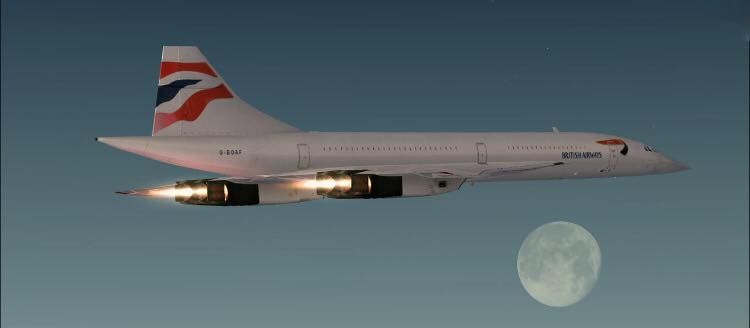
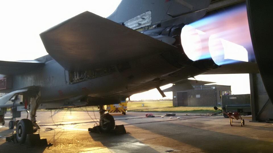
regards
Howie
Just found this pic on the www and I think the reheat looks a bit ragged compared to the Reheated Engines I have worked on - RR Spey & RB199.
Is this a representative sort of view or a false picture and the real thing is much neater with Mach Diamonds and the like???

regards
Howie