21st Dec 2010, 21:00
permalink Post: 934
A double engine failure, or even a double engine surge, could lead to a very nasty yaw, faster than the pilot, not necessarily instantly aware of exactly what was happening, could counter.
The designers were, right from the start, aware of this problem.
Hence, the prototypes were equipped with specific "contre automatique" (auto-rudder) computers, that would "kick in" a given rudder deflection as soon as they detected an engine failure (and twice as much in the case of a double failure).
Unfortunately... the manner of detecting an engine failure was based on pressure sensors in the engine, which proved to be notoriously unreliable.
Since the whole system was "fail-passive", in the case of a pressure sensor failure nothing happened, other than that I got the "suspect" computer dumped in my lap every time, since it was easier to swap a computer than test and swap pressure sensors....
In the end, it was always "no fault found", and the engineers had to go and test the sensors to find the failed one.
Already on the pre-production aircraft, this Rube Goldberg system was replaced by a single circuit board 'buried' in the autostab computer.
It used a lateral accelerometer to detect the abrupt yaw of a sudden engine failure or surge, and applied appropriate rudder. Look at the sudden rudder deflection 'peak' on the lateral response graph in the previous post.
Since there was no separate 'auto-rudder engage' control switch (the function was permanently active), and it was only mentioned very much in passing during training, some pilots were not even aware it existed.......
CJ
22nd Dec 2010, 07:18
permalink Post: 935
Thumbs Up for CJ, CliveL, M2Dude and other guys.

I'm wondering that does the auto-stab function in yaw axis does apply some
rudder when pilot fly the aircraft by his hand to prevent the sideslip or
dutchroll or not?
Also, does the auto stab does "modify" some pilot input to minimize the effect
of the turbulence all the time when airplane encounter the turbulence or only
when the AP are in the "TURB" mode? Does it help to reduce the stress on the
aircraft like the "load alleviation" on the moder aircraft like A380?
And final the final question, how the camber help to reduce the shifting
position of the center of pressure on the Concorde and if possible where is it
on the wing?
Thanks for all of yours reply.
Best regards
Last edited by Mr.Vortex; 22nd Dec 2010 at 07:21 . Reason: Forgot something...
22nd Dec 2010, 08:28
permalink Post: 937
MrVortex
Concorde had triple-axis auto stabilisation, where pilot demands were routed via an AUTOSTAB COMPUTER and summed with any stabilisation demands. There was automatc roll/yaw crossfeed, where for a given roll demand there was a coresponding amount of rudder applied, the amount of which was a function of Mach number. As far as 'dutch roll' etc the autostab system employed rate gyros in the same way as a conventional 'yaw damper' would operate in an inferior
 (oops, my bad.. I mean SLOWER) aircraft.
The AUTOSTAB operated full time, irrespective of AFCS mode. (Perhaps EXWOK, NW1 or one of the other boys will confirm that TURB mode was seldom EVER used in airline service. It was a (if I remember correctly) a Pitch/HDG hold autopilot mode with reduced gain).
Best regards
Dude
Quote:
| I'm wondering that does the auto-stab function in yaw axis does apply some rudder when pilot fly the aircraft by his hand to prevent the sideslip or dutchroll or not? |
(oops, my bad.. I mean SLOWER) aircraft.
Quote:
| Also, does the auto stab does "modify" some pilot input to minimize the effect of the turbulence all the time when airplane encounter the turbulence or only when the AP are in the "TURB" mode? Does it help to reduce the stress on the aircraft like the "load alleviation" on the moder aircraft like A380? |
Best regards
Dude
22nd Dec 2010, 08:29
permalink Post: 938
Quote:
|
Originally Posted by
Mr Vortex
I'm wondering that does the auto-stab function in yaw axis does apply some
rudder when pilot fly the aircraft by his hand to prevent the sideslip or dutchroll or not? Also, does the auto stab does "modify" some pilot input to minimize the effect of the turbulence all the time when airplane encounter the turbulence or only when the AP are in the "TURB" mode? Does it help to reduce the stress on the aircraft like the "load alleviation" on the moder aircraft like A380? And final the final question, how the camber help to reduce the shifting position of the center of pressure on the Concorde and if possible where is it on the wing? |
Then, yes the autostabiliser does provide yaw damping to control the Dutch roll, but there was also (from memory) some roll damping.
No, there is no load alleviation function. Concorde had a very low aspect ratio wing which gives in turn a very low lift curve slope, so the loads coming from hitting gusts are quite modest and load alleviation was not needed. The autostabiliser was working all the time, not just when A/P was engaged. Since the span was also low the manoeuvre bending moment was also small so again load alleviation was not required. BTW, I believe that the A380 load alleviation is just this manoeuvre case not gust loads. The A320 had gust load alleviation on early models, but it proved to be a pain in the neck and was gratefully dropped when the MTOW went up and made manoeuvre loads the critical design case.
Finally, the camber is spread all over the wing. In cross section it looks like a banana with the bent bit like a shallow 'U' and the leading edge drooped downwards, so the whole thing lookss like a distorted 'S'
CliveL
22nd Dec 2010, 14:50
permalink Post: 941
Quote:
|
Originally Posted by
M2dude
Concorde had triple-axis auto stabilisation, where pilot demands were routed via an AUTOSTAB COMPUTER and summed with any stabilisation demands.
|
Pilot demands in manual flight produced electrical signals corresponding to the control position, which were sent to the 'servo control amplifiers' (eight in all, one per control surface) which in turn commanded the PFCUs (power flying control units) that hydraulically moved the control surfaces.
Autopilot demands directly moved the pilot's controls (stick and rudder) via hydraulic cylinders (the 'relay jacks') so that the same signals as in manual flight then went to the servo control amplifiers.
The purpose of the autostab was to provide proper dynamic stability over the full flight envelope. The aircraft could be flown without autostab, but over some of the speed range it was only marginally stable.
The electrical signals from the autostab computing were fed directly into the servo control amplifiers, so there was no feedback to the pilot's controls, unlike the autopilot demands.
There was occasional confusion about exactly what did what and how and where.... because the servo control amplifiers - although a function independent of the autostab as such - were housed... in the autostab computers.
To complete the tale, this is what those servo control amplifiers look like.
The one of the left is from prototype 002, the one on the right from a production aircraft. To give them scale, the one on the right is about the size of a box of large kitchen/fireplace matches.
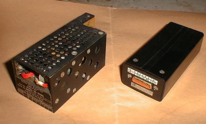
CJ
22nd Dec 2010, 17:01
permalink Post: 945
VOR tracking on Conc
You're right Christiaan - memories of the exact details are growing misty now, but I do remember trying to get the autoflight VOR tracking facility to work and not getting anything sensible. I (and everyone else I ever flew with) invariably used the INS to track to a VOR - or just tuned the station and flew it like an aeroplane using controls and needles. The Concorde aeroplane encouraged the latter technique because it was so rewarding (but occasionally deeply frustrating) to fly. Good days were phenominal. Bad days were... bad (Mike Riley put this well in his "Concorde - Stick and Rudder" book).
22nd Dec 2010, 20:13
permalink Post: 950
Quote:
|
Originally Posted by
exwok
Hazy recollection - effectively an additional autostabilisation input in the nosedown sense active at high alpha/low EAS.
Ultimately applied a further nose down elevon input (4 degrees????) if EAS was less than (140kts???? That's a VERY low speed). (Colloquially known as 'super-duper stab' on my course) |
To cover this case the 'superautostabiliser'was developed. It effectively restricts the rate of variation of incidence so that, if the pilot entered into an avoidance manoeuvre of sufficient magnitude to trigger the stick wobbler, i.e. about 1.5g, he would be able to recover easily without exceeding the maximum incidence demonstrated in flight (which was in fact slightly greater than the maximum steady incidence limit). This superautostab had gain scheduled against AoA and also included phase advanced pitch rate and speed terms. Finally, there was a 'yaw superautostabiliser which applied rudder as a function of lateral acceleration to restrict sideslip which (see below) could affect the maximum lift attainable. [Note that because of the dynamics of slender aircraft operating at high AoA it was readily possible to develop sideslip in a turn]
Hope that is clear.
Whilst talking about maximum lift etc. can I confirm the numbers quoted in an earlier posting for the start of vortex lift - about 6 or 7 deg AoA at low speed, and for the AoA at maximum lift - about 23 deg. This is where the pitching momemt curve vs AoA 'breaks'. It is not a stall in the conventional sense because of course the flow over the leading edge has been separated long ago. Instead it is the AoA at which the LE vortices become 'too big for their boots' and go unstable and 'burst'. This AoA is sensitive to sideslip and the leading wing half will go first.
CliveL
24th Dec 2010, 16:15
permalink Post: 991
Thanks again for a great pics and great explanation.
I'm was wondering that, according to the manual and some document said
that the vortex lift start to form on wing tip first. Why's that happened?
Why not the root of the wing first?
Is it cause by the local wing tip vortex push the air causing more upwash
and hence more effective AoA causing it to reach the stall AoA first is that right?
Also, does the wing vortex on the Concorde has an influence or the effect on
the rudder?
Thanks for your reply.
Best regards
24th Dec 2010, 17:56
permalink Post: 997
[xxxxquote=Mike Bracknell]
Trust me, i'm definitely just here for the ride (so to speak) and quickly defer to you and the others who definitely know! Mike Bracknell[xxxx/quote]
Hell Mike, I meant I should leave it for others who definitely know, not you!
[xxxxquote]A little p.s. from me - having looked at Clive's diagram on this page showing the bathtubs, aren't the strengtheners the oval cups outboard of the main fixings on the page? with one pointed to by the words "Bottom machined skin panel"?
This looks like it's another layer of shear in order to fulfil the brief of working around the reported skin problems in that area. Just strange it had to break the surface like that? [xxxx/quote]
I don't think so Mike, there are far too many of them. It looks more like 'pocketing' of the machined skin to reduce weight; and incidentally that SA overdid it, since there were clearly cracks developing along the spanwise joints between the various wing sections.
Incidentally, doesn't that picture show ever so clearly why designing and fitting that postGonesse Kevlar liner to the lower skins was such a difficult job!
[xxxxquote=ChristiaanJ]If so, they are indeed shown in the structural repair manual and listed as 'doublers'. There are ten of those, from spar 62 to spar 71.
Reading "between the lines", the modification dates from about 1978, and was applied by successive service bulletins to both the BA and AF aircraft. [xxxx/quote]
Yes, I agree, they look like skin doublers put on as a repair job, and that makes (to me) a lot more sense than additions to increase outer wing stiffness. What has confused me from the beginning was that I equated "outer wing stiffness" with "outer wing torsional stiffness" because I could see why somebody might want to increase that but I couldn't, and can't, see why anyone would want to increase outer wing bending stiffness - if you get a little more dihedral who cares? But additional material to increase or recover fatigue life is another matter altogether.
Why external? Just look at that drawing - where could you add additional bending material easily?
[xxxxquote=Landroger]Digital control is a hell of a lot easier than Analogue - in my humble opinion.[xxxx/quote]
Depends when you were born Roger. Now if you came into this world before WW2 ......
[xxxxquote=Mr Vortex]I'm was wondering that, according to the manual and some document said that the vortex lift start to form on wing tip first. Why's that happened? Why not the root of the wing first?
Is it cause by the local wing tip vortex push the air causing more upwash
and hence more effective AoA causing it to reach the stall AoA first is that right?
Also, does the wing vortex on the Concorde has an influence or the effect on
the rudder? [xxxx/quote]
Ah! this gets a little complicated. Every lifting wing generates a pair of vortices at the tip, but these are not the vortices most people associate with Concorde. The massive vortices you see when the air is moist and the water vapour condenses out because of the drop in air pressure inside the vortex start, as you suggest at the wing root from that highly swept leading edge. The wingtip vortices are still there, even when the main vortices are doing their stuff, so Concorde actually has two sets of vortices acting on the upper surface, although this is not obvious to the casual observer.
Simply, the wing vortex has no effect on the rudder.
But whilst I am writing about vortices, can I digress to talk about the 'moustaches' aka GT6. Somebody, I forget who, asked about their use for controlling longitudinal stability and somebody else replied, quite correctly, that they were a contribution to lateral stability. What was happening without them was that high AoA (by which I mean in excess of about 10~12 degrees) the 'crossflow' on the front fuselage generated a pair of small vortices which, in sideslip, wandered across the base of the fin. This gave some sidewash that cancelled the 'incidence' coming from the sideslip itself so that the bottom of the fin was effectively operating at zero slip and therefore zero lift. Result - the weathercock stability dropped to virtually zero for small sideslip angles. The small vortex generators (Generator Turbillon or GT) had the effect of fixing the location of the origin of the forebody vortices so that they didn't wander - in fact they tended to become entrained into the main wing vortices - problem solved.
Now if I can sort it out I will try to upload some pretty pictures showing those two sets of wing vortices.
CliveL
16th Jan 2011, 09:41
permalink Post: 1110
SpeedbirdConcorde
Hi again my friend. To further expand on CliveJ's superb explanation: Mechanical control inputs were fed to each of the 8 Powerd Flying Control Units (PFCUs), but in electronic signalling (either Blue or Green) these inputs were de-clutched at the PFCU input lever. When Fly By Wire' signalling is not available, the mechanical inputs (which as CliveL quite rightly points out) are driven by the Relay Jacks, now are locked to the input lever and can now move the input jack of the PFCU (known as the spool valve) and subsequently cause the PFCU to drive the control surface. (The body of the PFCU moved, the main jacks were attached at each end to structure and so obviously did not move). Hopefully this diagram will help visualising the process a little easier:
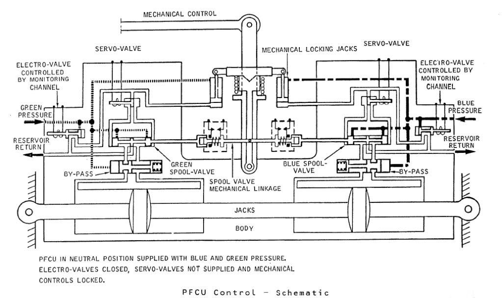
The diagram shows Green & Blue hydraulics supplied but the electro-valves (opened by the respective FBW channel) are both closed. You can see that the mechanical input lever is 'locked' to the PFCU input lever which will drive the SPOOL VALVE directly. When FBW is enabled, either the Blue or Green (never both together) ELECTRO-VALVE are signalled open, the ensuing hydraulic pressure then pushing the input clutch upwards and disengaging the mechanical input. FBW demands are now fed to the respective SERVO VALVE which will hydraulically send the SPOOL VALVE in the desired direction.
The Relay Jacks could be considered to be a little like a PFCU (you had 2 RJs per axix) but instead of the servo valves being driven by the FBW system they were driven by the autopilot and instead of driving a control surface, they drove the control runs. In manual flight the input spool was driven via a mechanical input lever, which would drive the RJ spool a little like Mech' signalling drove the PFCU spool. In A/P mode the mechanical input rod was de-clutched \xe0 la PFCU, but (and here's the clever part) this input was locked to the body of the Relay Jack which when it moved, drove the pilot's control in sympathy. (Control column, yoke or rudder pradals). As the respective control(s) was moved by the Relay Jack, the corresponding FBW position sensor (resolver) would change position and generate the FBW demand. (As the surface moved there was a feedback resolver at PFCU level).
As far as the FBW channels themselves went; there were 2 electronic signalling modes, Blue and Green, sub-divided into 3 groups (Inner Elevons, Outer & Mid Elevons and Rudders). Each group was independently monitored, and a fault in say the Rudder channel alone, would result in the rudders ONLY changing lanes. NOW ( ), The normal control channel was BLUE, and if this failed you would drop the respective channel into GREEN and if this failed you would drop into MECH. The selector switches (1 per group) enabled you to select BLUE/GREEN/MECH in that order. If for some reason you were selected to GREEN, a failure of that signalling lane would not drop you 'up' into BLUE, but into MECH. Your switch would only be in this position if you'd had a problem with BLUE, however you would select this on pushback while you were testing the flying controls, otherwise you spent your whole life selected to BLUE. As far as BA went, I can never remember a time personally when all 3 groups dropped from BLUE to MECH, but very rarely you might get a fault that caused a single group to briefly drop to MECH. Just about one of the very few common mode failures to each of the 3 groups would be a failure of the respective FBW static inverter. This thing, which was rightly monitored up to the hilt, produced a 26 Volt 1800 Hz output. (1800 Hz was chosen as this is not a harmonic of aircraft mainline 400 Hz AC supply)
Best regards
Dude
Hi again my friend. To further expand on CliveJ's superb explanation: Mechanical control inputs were fed to each of the 8 Powerd Flying Control Units (PFCUs), but in electronic signalling (either Blue or Green) these inputs were de-clutched at the PFCU input lever. When Fly By Wire' signalling is not available, the mechanical inputs (which as CliveL quite rightly points out) are driven by the Relay Jacks, now are locked to the input lever and can now move the input jack of the PFCU (known as the spool valve) and subsequently cause the PFCU to drive the control surface. (The body of the PFCU moved, the main jacks were attached at each end to structure and so obviously did not move). Hopefully this diagram will help visualising the process a little easier:
The diagram shows Green & Blue hydraulics supplied but the electro-valves (opened by the respective FBW channel) are both closed. You can see that the mechanical input lever is 'locked' to the PFCU input lever which will drive the SPOOL VALVE directly. When FBW is enabled, either the Blue or Green (never both together) ELECTRO-VALVE are signalled open, the ensuing hydraulic pressure then pushing the input clutch upwards and disengaging the mechanical input. FBW demands are now fed to the respective SERVO VALVE which will hydraulically send the SPOOL VALVE in the desired direction.
The Relay Jacks could be considered to be a little like a PFCU (you had 2 RJs per axix) but instead of the servo valves being driven by the FBW system they were driven by the autopilot and instead of driving a control surface, they drove the control runs. In manual flight the input spool was driven via a mechanical input lever, which would drive the RJ spool a little like Mech' signalling drove the PFCU spool. In A/P mode the mechanical input rod was de-clutched \xe0 la PFCU, but (and here's the clever part) this input was locked to the body of the Relay Jack which when it moved, drove the pilot's control in sympathy. (Control column, yoke or rudder pradals). As the respective control(s) was moved by the Relay Jack, the corresponding FBW position sensor (resolver) would change position and generate the FBW demand. (As the surface moved there was a feedback resolver at PFCU level).
As far as the FBW channels themselves went; there were 2 electronic signalling modes, Blue and Green, sub-divided into 3 groups (Inner Elevons, Outer & Mid Elevons and Rudders). Each group was independently monitored, and a fault in say the Rudder channel alone, would result in the rudders ONLY changing lanes. NOW ( ), The normal control channel was BLUE, and if this failed you would drop the respective channel into GREEN and if this failed you would drop into MECH. The selector switches (1 per group) enabled you to select BLUE/GREEN/MECH in that order. If for some reason you were selected to GREEN, a failure of that signalling lane would not drop you 'up' into BLUE, but into MECH. Your switch would only be in this position if you'd had a problem with BLUE, however you would select this on pushback while you were testing the flying controls, otherwise you spent your whole life selected to BLUE. As far as BA went, I can never remember a time personally when all 3 groups dropped from BLUE to MECH, but very rarely you might get a fault that caused a single group to briefly drop to MECH. Just about one of the very few common mode failures to each of the 3 groups would be a failure of the respective FBW static inverter. This thing, which was rightly monitored up to the hilt, produced a 26 Volt 1800 Hz output. (1800 Hz was chosen as this is not a harmonic of aircraft mainline 400 Hz AC supply)
Best regards
Dude
Last edited by M2dude; 16th Jan 2011 at 12:10 . Reason: Clarity; Oh for clarity
3rd Apr 2011, 21:16
permalink Post: 1252
Bellerophon
I remember that -- the initial rotation was pretty normal other than being a bit faster, then from there it was brought up to a very steep climb (it feels worse than it is, but I was guessing it was around 22 or so degrees -- it has to do with eyeballing the angle of the horizon to the plane's current path -- 22.5 degrees is 1/4 the way up, 30 is 1/3, 45 is 1/2, 60 is 2/3's and so forth). Clearly I'm not a human ADI

Quote:
|
You call 3-2-1 Now, start your stopwatch, pre-set to countdown from 58 seconds, and slam the throttles fully forward till they hit the stops. Four RR Olympus engines start to spool up to full power and four reheats kick in, together producing 156,000 lbs of thrust, but at a total fuel flow of 27,000 US gallons per hour. A touch of left rudder initially to keep straight, as the #4 engine limiter is limiting the engine to 88% until 60 kts when it will release it to full power. The F/O calls
Airspeed building, 100 kts, V1
, and then, at 195 kts,
Rotate
. You smoothly rotate the aircraft, lift-off occurs at around 10\xb0 and 215 kts. You hear a call of
V2
but you keep rotating to 13.5\xb0 and then hold that attitude, letting the aircraft accelerate.
The F/O calls Positive Climb and you call for the Gear Up . On passing 20 feet radio height, and having checked the aircraft attitude, airspeed and rate of climb are all satisfactory, the F/O calls Turn and you slowly and smoothly roll on 25\xb0 left bank to commence the turn out over Jamaica bay. Some knowledgeable passengers will have requested window seats on the left side of the aircraft at check-in, and are now being rewarded with a very close look at the waters of Jamaica Bay going by very fast! As you accelerate through 240 kts, the F/O calls 240 and you pitch up to 19\xb0 to maintain 250 kts and keep the left turn going to pass East of CRI. |
9th Apr 2011, 17:17
permalink Post: 1292
If I may be permitted to tread drift a bit re engine rotation effects: prop-driven aircraft suffer a range of unpleasant effects that jets don't. Not least is the prop slipstream effect; the propwash spirals around the aeroplane and pushes on the fin inducing a turn. This is at its worst at take off, with no slipstream and high power; even our Chipmunk needs a bootful of left rudder to keep straight when full power is applied at the start of the take-off roll. A really powerful aeroplane like a Spitfire cannot use full power until there is sufficient airspeed to make the rudder effective enough to keep straight; one reason why later Spits had contra-rotating props.
Then, for a taildragger like the Chippy, there's the 'assymetric blade effect' or 'p' factor, where with the tail down the down-going prop blade produces more thrust than the up-going one. And the engine torque effect particularly noticable on soft runways with powerful aeroplane where one mainwheel tyre is pushed into the ground with more force than the other, and finally the gyroscopic swing induced in a taildragger as the tail comes up and the prop disc is tilted to the vertical.
All of these effects are cumulative, and it's one reason why tail-wheel prop pilots learn to use their feet! All are obviated by contra-rotating props or, for twins, 'handed' engines which rotate in opoosite directions to each other.
When I had a share in a Yak52 I used to use the 'engine torque effect' to steer the aeroplane on Barton's muddy winter surface; using the conventional method (braking the appropriate mainwheel; the nosewheel was free-castoring) didn't work as the (quite thin) wheel would just lock and slide along, not inducing a change of direction at all. But whack on a fistful of Vendeneyef and 360hp would dig the right main into the ground and she'd turn right. Pull the power off suddenly and the left main would dig in, turning her left. Worked a treat!
21st Jun 2011, 06:14
permalink Post: 1385
Thanks for that much better picture Bellerephon.
I have a bit more information now, although my French is very rusty so I may not have it all correct - CJ can probably correct me if necessary.
They did 8 flights over 10 hrs, preceded by about 30 simulator 'flights'. Most of the flight testing was looking at low speed behaviour, since that was where they expected to see most gains on Concorde, and where the most problems might be expected, but they did go up to 2.04M. The primary advantage was seen to be the possibility of using very aft CGs for takeoff to reduce trim drag - they flight tested as far back as 56% at around 0.4M (no consideration of limits from U/C location of course for this sort of testing). In addition they were predicting a weight saving of around half a tonne.
The simulator work sorted out the basic laws, where they tested a pure pitch rate feedback and a C* law with load factor and pitch rate terms. The pilots preferred the latter (which became in time the basis for the A320 laws).
The simulator was also used to establish the best ergonomics (movement and force harmonisation) of the sidestick.
The 'blue' electrical signalling system for elevons was replaced by the digital control and sidestick arrangement, keeping the 'green' signalling as a safety backup. Normal rudder control system was retained, as well as the mechanical backup.
In the general arrangement of the digital control system one can see clearly the genesis of the A320 design - two computers with the software written by separate teams etc.
Pilot reaction seems to have been very favourable, the aircraft being somewhat easier to fly than the basic Concorde (which was already pretty good ....).
In particular the paper suggests that the precision with which the aircraft could be positioned was much improved.
Stick force per 'g' was pretty much the same throughout the speed range at about 7daN/g, whereas on Concorde it varies from 20 to 40 daN/g - but on a sidestick rather than a control column of course.
One problem that did show up, although not peculiar to Concorde, was the sensitivity of these systems to structural response, particularly during ground roll.
Not contained in the report, but in a side letter from Dudley, is a remark that the guy most responsible for the development of the Concorde basic system and later in charge of the Airbus system thought that these Concorde experiments were the key to the success of the A320.
'Nuff said!
CliveL
1st Aug 2012, 07:51
permalink Post: 1660
Words almost fail me...
I am on page 49 of this amazing thread about an incredible aircraft. I have spent many "unproductive" hours at my desk \x96 when I should be defending the free world \x96 reading here.
I must say, this is an incredibly brilliant (in the US sense of "intellect" rather than the British "cool/great") people. The history; the technology; and, most importantly, the people here make this a thread beyond compare \x96 more alive than any book on the topic could hope to be.
Sometime, roughly ~1987?, I was driving from Norfolk, Virginia, to Washington, DC. As I drove by the Wilmington, Delaware, airport I saw an unusual looking tail rising above a building. I thought, "That looks like Concorde, but she wouldn't be here . Several seconds later the building no longer blocked my view, and it was indeed Concorde!
I had previously seen the a/c on display at the Musee de l'air in Paris and have since seen the one in Sinsheim, Germany. Wilmington, though, was the only time I actually saw one in service.
Long into, now to my question:
A few pages back I read about "left rudder" on takeoff because "engine number four was at 88% thrust." I understand the need for rudder based on asymmetric thrust, but why was the thrust asymmetric in the first place?
I need to push on through the next 40 pages to get the answer to my question!
4th Dec 2013, 10:38
permalink Post: 1762
I understand it fell victim to the dreaded Canterbury Nor'west wind. From memory, a servicing platform got blown about and punctured a fuel tank. It was reported in the local papers at the time but there was very little fuss made about the incident at the time.
There were several Concorde visits to Christchurch, all very popular to the locals (including myself). However, Concorde suffered at least two incidents that could be attributed to the Nor'west wind at Christchurch. The other one that gained more publicity was when it lost part of its rudder flying across the Tasman sea. There was some evidence that when parked overnight at Christchurch airport, the wind came up and started slamming the unlocked rudder about...
There were several Concorde visits to Christchurch, all very popular to the locals (including myself). However, Concorde suffered at least two incidents that could be attributed to the Nor'west wind at Christchurch. The other one that gained more publicity was when it lost part of its rudder flying across the Tasman sea. There was some evidence that when parked overnight at Christchurch airport, the wind came up and started slamming the unlocked rudder about...
5th Dec 2013, 11:33
permalink Post: 1763
This totally corroborates the account given to me. Didn't realise that the rudder problem was caused by the same phenomenon. Who would have thunk it!
6th Dec 2013, 02:41
permalink Post: 1764
..... not convinced that theory's true.....
The PFCUs will offer a lot of damping, even while unpressurised. I've never seen a control surface 'slam' side to side on a hydraulically powered aircraft for tis reason.
The cause of the rudder failure was internal corrosion brought about by a mod which added a fillet to the trailing edge.
I suggest the surface winds were a red herring.
20th May 2016, 04:01
permalink Post: 1942
Is this the best thread on the Internet?
98 Pages - have read them all. Absolutely unique given the tailspin that a lot of threads (not just on this site) find themselves in - this thread is a credit to those who have made it so captivating.
I lived in the UK for 10 years and was lucky enough to (well my wife did) win a return for 2 to NY on Concorde. Courtesy of the Evening Standard. This was June 1997. We sat in 3A/B and as an avid aviation follower (my dad flew in the RNZAF) spent way longer than my welcome in the cockpit when it was our turn. Purely because unlike a lot of other people who pointed and wowed - I spoke to the F/E and the skipper (Mike Bannister) about the flying aspect and marvelled at the engineering and the systems.
My dad broke the sound barrier in 1963 in an F-105 in Thailand somewhere whilst on manoeuvres with the USAF and as a wee chap always remember the mach meter at 1.06. So I asked Capt Bannister if he would take a picture of this for me from the same aspect - and he did. I proudly showed my dad.
So on the way back from NY on boarding I asked the Chief Purser if there was any chance of sitting in the cockpit for landing - a fairly stern no was the answer. No problem - 3 hours of caviar, mango, fillet steak and Krug ensued.
Then lo and behold - about 25 minutes from landing, the purser found me and said (verbatim) - "are you the young chap whose dad broke the sound barrier? Capt Bannister would like to know if you would like to sit on the jump seat for landing." I levitated to the cockpit.
Was strapped in, given headphones - told not to talk unless spoken to (nicely of course). Mike Bannister did say to me that I was one of the few people (of 100) to actually pay any interest to the flight systems aspect - which was why he asked if I was keen to join them for landing.
Oh the good old days!!
At the time we lived in Brockham and as a bonus it transpired that Bill Clinton and Air Force One was in the circuit and as it was explained to me - there was an exclusion zone whilst Air Force 1 was on finals? So we had to do 2 laps of the Ockham circuit. Which as fate would have it was almost directly over my house.
In all a surreal experience - just over 24 hours LHR - JFK - LHR return - didn't sleep a wink.
So not really a contribution to the thread - but a memory of a whirlwind, never to be repeated 24 hours. I think I was unbelievably lucky.
About the only thing I recall about Concorde (by way of a question) that I can't recall seeing here was when Concorde visited Auckland in the late 70's? Was the damage to either the rudder or a stabiliser? Surely at Mach 2.0 the vibrations/difference in control would be marked? From memory the flight crew was interviewed and I'm sure they said they didn't notice anything? Comments?
18th Jul 2016, 06:52
permalink Post: 1946
Roger. Great first post!. I too have been lucky enough to 'flight-deck' Concorde as a passenger, tho' not for the landing. {Did that as a pax in a Trident, amongst others!] I still have the video that I took!. Like you, I was interested in the flying of it, and asked questions, but didn't have the same luck as you with the jump seat.
I recently flew Heathrow to Kuala Lumpur in an A.380, and whilst driving from Croydon to Heathrow, went along the road at the side of BA Engineering, and there, looking beautiful in the sun, was 'my' Concorde, G-BOAB. Happy memories!. There was, I believe, the occasional rudder skin loss on a couple of Concordes, and vibration was experienced if I remember correctly.
I recently flew Heathrow to Kuala Lumpur in an A.380, and whilst driving from Croydon to Heathrow, went along the road at the side of BA Engineering, and there, looking beautiful in the sun, was 'my' Concorde, G-BOAB. Happy memories!. There was, I believe, the occasional rudder skin loss on a couple of Concordes, and vibration was experienced if I remember correctly.