21st Dec 2010, 16:53
permalink Post: 926
quote:
d putting further Concorde's achievements in terms of stability; the world's only previous large delta winged Mach 2 aircraft, the B58 Hustler, had the slightly awkward feature in the case of an outer engine failure at Mach 2, in that the yaw forces were sufficient to tear the fin off. This happened on more than one occasion during service life of the Hustler, but engine failure (or far more likely a deliberate precautionary shut-down) although hardly a non-event in the case of Concorde, it was routinely dealt with without drama or danger.unquote
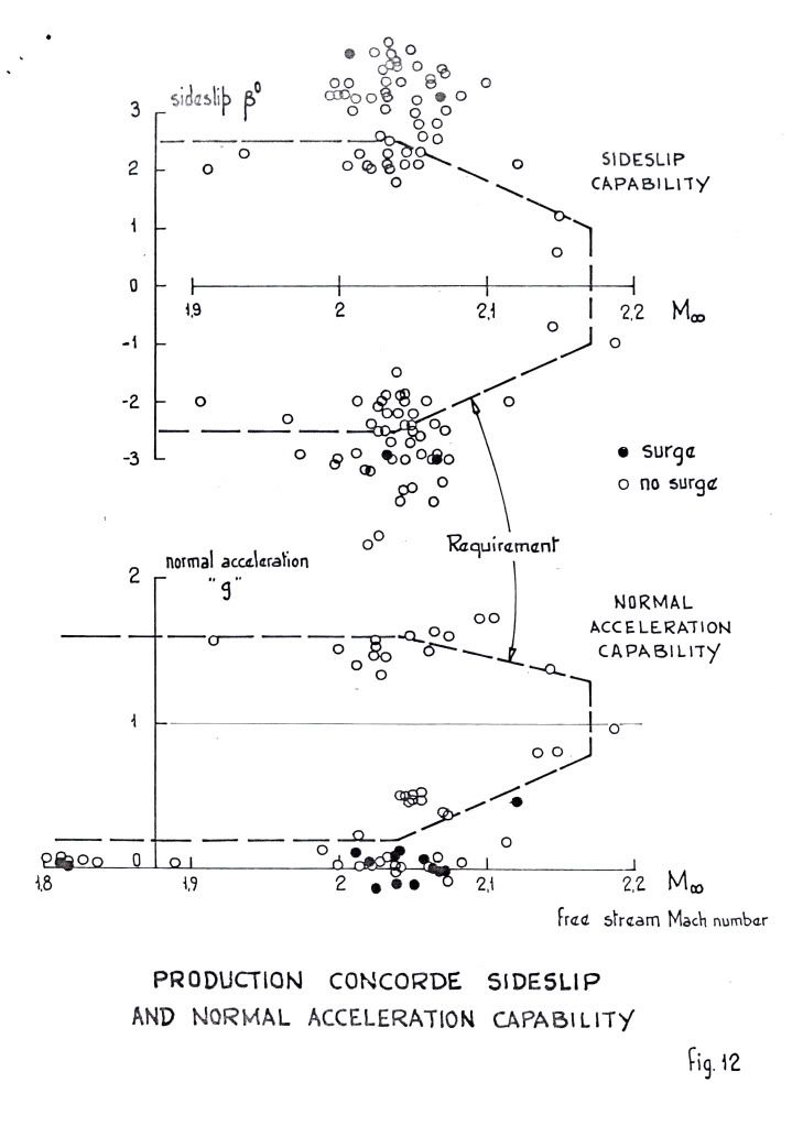
To rub it in, a typical double engine surge - they were nearly always double surges as the first surge expelled the ramp shock waves and turned the flow into a pitot with a large standing shock ahead of the intake that screwed up the flow into its neighbour - would produce about 1 degree sideslip and 2 deg bank. There would be a +/- 0.2g variation in normal acceleration and that was it! Through Christiaan's kind offices I am posting the records of such an event.
Hustler pilots eat your heart out!
CliveL
22nd Dec 2010, 07:18
permalink Post: 935
Thumbs Up for CJ, CliveL, M2Dude and other guys.

I'm wondering that does the auto-stab function in yaw axis does apply some
rudder when pilot fly the aircraft by his hand to prevent the sideslip or
dutchroll or not?
Also, does the auto stab does "modify" some pilot input to minimize the effect
of the turbulence all the time when airplane encounter the turbulence or only
when the AP are in the "TURB" mode? Does it help to reduce the stress on the
aircraft like the "load alleviation" on the moder aircraft like A380?
And final the final question, how the camber help to reduce the shifting
position of the center of pressure on the Concorde and if possible where is it
on the wing?
Thanks for all of yours reply.
Best regards
Last edited by Mr.Vortex; 22nd Dec 2010 at 07:21 . Reason: Forgot something...
22nd Dec 2010, 08:28
permalink Post: 937
MrVortex
Concorde had triple-axis auto stabilisation, where pilot demands were routed via an AUTOSTAB COMPUTER and summed with any stabilisation demands. There was automatc roll/yaw crossfeed, where for a given roll demand there was a coresponding amount of rudder applied, the amount of which was a function of Mach number. As far as 'dutch roll' etc the autostab system employed rate gyros in the same way as a conventional 'yaw damper' would operate in an inferior
 (oops, my bad.. I mean SLOWER) aircraft.
The AUTOSTAB operated full time, irrespective of AFCS mode. (Perhaps EXWOK, NW1 or one of the other boys will confirm that TURB mode was seldom EVER used in airline service. It was a (if I remember correctly) a Pitch/HDG hold autopilot mode with reduced gain).
Best regards
Dude
Quote:
| I'm wondering that does the auto-stab function in yaw axis does apply some rudder when pilot fly the aircraft by his hand to prevent the sideslip or dutchroll or not? |
(oops, my bad.. I mean SLOWER) aircraft.
Quote:
| Also, does the auto stab does "modify" some pilot input to minimize the effect of the turbulence all the time when airplane encounter the turbulence or only when the AP are in the "TURB" mode? Does it help to reduce the stress on the aircraft like the "load alleviation" on the moder aircraft like A380? |
Best regards
Dude
22nd Dec 2010, 08:29
permalink Post: 938
Quote:
|
Originally Posted by
Mr Vortex
I'm wondering that does the auto-stab function in yaw axis does apply some
rudder when pilot fly the aircraft by his hand to prevent the sideslip or dutchroll or not? Also, does the auto stab does "modify" some pilot input to minimize the effect of the turbulence all the time when airplane encounter the turbulence or only when the AP are in the "TURB" mode? Does it help to reduce the stress on the aircraft like the "load alleviation" on the moder aircraft like A380? And final the final question, how the camber help to reduce the shifting position of the center of pressure on the Concorde and if possible where is it on the wing? |
Then, yes the autostabiliser does provide yaw damping to control the Dutch roll, but there was also (from memory) some roll damping.
No, there is no load alleviation function. Concorde had a very low aspect ratio wing which gives in turn a very low lift curve slope, so the loads coming from hitting gusts are quite modest and load alleviation was not needed. The autostabiliser was working all the time, not just when A/P was engaged. Since the span was also low the manoeuvre bending moment was also small so again load alleviation was not required. BTW, I believe that the A380 load alleviation is just this manoeuvre case not gust loads. The A320 had gust load alleviation on early models, but it proved to be a pain in the neck and was gratefully dropped when the MTOW went up and made manoeuvre loads the critical design case.
Finally, the camber is spread all over the wing. In cross section it looks like a banana with the bent bit like a shallow 'U' and the leading edge drooped downwards, so the whole thing lookss like a distorted 'S'
CliveL
22nd Dec 2010, 20:13
permalink Post: 950
Quote:
|
Originally Posted by
exwok
Hazy recollection - effectively an additional autostabilisation input in the nosedown sense active at high alpha/low EAS.
Ultimately applied a further nose down elevon input (4 degrees????) if EAS was less than (140kts???? That's a VERY low speed). (Colloquially known as 'super-duper stab' on my course) |
To cover this case the 'superautostabiliser'was developed. It effectively restricts the rate of variation of incidence so that, if the pilot entered into an avoidance manoeuvre of sufficient magnitude to trigger the stick wobbler, i.e. about 1.5g, he would be able to recover easily without exceeding the maximum incidence demonstrated in flight (which was in fact slightly greater than the maximum steady incidence limit). This superautostab had gain scheduled against AoA and also included phase advanced pitch rate and speed terms. Finally, there was a 'yaw superautostabiliser which applied rudder as a function of lateral acceleration to restrict sideslip which (see below) could affect the maximum lift attainable. [Note that because of the dynamics of slender aircraft operating at high AoA it was readily possible to develop sideslip in a turn]
Hope that is clear.
Whilst talking about maximum lift etc. can I confirm the numbers quoted in an earlier posting for the start of vortex lift - about 6 or 7 deg AoA at low speed, and for the AoA at maximum lift - about 23 deg. This is where the pitching momemt curve vs AoA 'breaks'. It is not a stall in the conventional sense because of course the flow over the leading edge has been separated long ago. Instead it is the AoA at which the LE vortices become 'too big for their boots' and go unstable and 'burst'. This AoA is sensitive to sideslip and the leading wing half will go first.
CliveL
24th Dec 2010, 17:56
permalink Post: 997
[xxxxquote=Mike Bracknell]
Trust me, i'm definitely just here for the ride (so to speak) and quickly defer to you and the others who definitely know! Mike Bracknell[xxxx/quote]
Hell Mike, I meant I should leave it for others who definitely know, not you!
[xxxxquote]A little p.s. from me - having looked at Clive's diagram on this page showing the bathtubs, aren't the strengtheners the oval cups outboard of the main fixings on the page? with one pointed to by the words "Bottom machined skin panel"?
This looks like it's another layer of shear in order to fulfil the brief of working around the reported skin problems in that area. Just strange it had to break the surface like that? [xxxx/quote]
I don't think so Mike, there are far too many of them. It looks more like 'pocketing' of the machined skin to reduce weight; and incidentally that SA overdid it, since there were clearly cracks developing along the spanwise joints between the various wing sections.
Incidentally, doesn't that picture show ever so clearly why designing and fitting that postGonesse Kevlar liner to the lower skins was such a difficult job!
[xxxxquote=ChristiaanJ]If so, they are indeed shown in the structural repair manual and listed as 'doublers'. There are ten of those, from spar 62 to spar 71.
Reading "between the lines", the modification dates from about 1978, and was applied by successive service bulletins to both the BA and AF aircraft. [xxxx/quote]
Yes, I agree, they look like skin doublers put on as a repair job, and that makes (to me) a lot more sense than additions to increase outer wing stiffness. What has confused me from the beginning was that I equated "outer wing stiffness" with "outer wing torsional stiffness" because I could see why somebody might want to increase that but I couldn't, and can't, see why anyone would want to increase outer wing bending stiffness - if you get a little more dihedral who cares? But additional material to increase or recover fatigue life is another matter altogether.
Why external? Just look at that drawing - where could you add additional bending material easily?
[xxxxquote=Landroger]Digital control is a hell of a lot easier than Analogue - in my humble opinion.[xxxx/quote]
Depends when you were born Roger. Now if you came into this world before WW2 ......
[xxxxquote=Mr Vortex]I'm was wondering that, according to the manual and some document said that the vortex lift start to form on wing tip first. Why's that happened? Why not the root of the wing first?
Is it cause by the local wing tip vortex push the air causing more upwash
and hence more effective AoA causing it to reach the stall AoA first is that right?
Also, does the wing vortex on the Concorde has an influence or the effect on
the rudder? [xxxx/quote]
Ah! this gets a little complicated. Every lifting wing generates a pair of vortices at the tip, but these are not the vortices most people associate with Concorde. The massive vortices you see when the air is moist and the water vapour condenses out because of the drop in air pressure inside the vortex start, as you suggest at the wing root from that highly swept leading edge. The wingtip vortices are still there, even when the main vortices are doing their stuff, so Concorde actually has two sets of vortices acting on the upper surface, although this is not obvious to the casual observer.
Simply, the wing vortex has no effect on the rudder.
But whilst I am writing about vortices, can I digress to talk about the 'moustaches' aka GT6. Somebody, I forget who, asked about their use for controlling longitudinal stability and somebody else replied, quite correctly, that they were a contribution to lateral stability. What was happening without them was that high AoA (by which I mean in excess of about 10~12 degrees) the 'crossflow' on the front fuselage generated a pair of small vortices which, in sideslip, wandered across the base of the fin. This gave some sidewash that cancelled the 'incidence' coming from the sideslip itself so that the bottom of the fin was effectively operating at zero slip and therefore zero lift. Result - the weathercock stability dropped to virtually zero for small sideslip angles. The small vortex generators (Generator Turbillon or GT) had the effect of fixing the location of the origin of the forebody vortices so that they didn't wander - in fact they tended to become entrained into the main wing vortices - problem solved.
Now if I can sort it out I will try to upload some pretty pictures showing those two sets of wing vortices.
CliveL
24th Dec 2010, 18:25
permalink Post: 998
 ">
">
Dammit! I thought I had read that [xxxxquote] gave me one of those pretty text boxes ah well, back to the drawing board.....
Unfortunately the only flow visualisation pictures I have are taken at AoAs where the tip vortex has been swallowed by the main vortex, but I thought I would paste them anyway as most people would never have seen them. In this one you can see the forebody vortices quite clearly (the bluegreen streaks) but since it is a zero sideslip case they don't go anywhere near the fin.
On closer inspection, maybe you can just see the wingtip vortices as separate bits of curly white smoke very close to each wingtip.
I'm not going to risk losing all that typing trying to attach a second picture, so I will send that separately
CliveL
13th Jan 2011, 11:10
permalink Post: 1083
Quote:
|
Originally Posted by
M2Dude
Really an answer for CliveL, but I'll have a go. The short answer to your question is 'oh yeah, big time'. Total temperature varies with the SQUARE of Mach number and static temperature. Depending on the height of the tropopause itself as well as other local factors, there can be little or no significant variation of static temperature between FL600 and FL700. The 400\xb0K (127\xb0C) Tmo limit was imposed for reasons of thermal fatigue life, and equates to Mach 2.0 at ISA +5. (Most of the time the lower than ISA +5 static air temperatures kept us well away from Tmo). In a nutshell, flying higher in the stratosphere gains you very little as far as temperature goes. (Even taking into account the very small positive lapse above FL 650 in a standard atmosphere). As far as the MAX SPEED bit goes, Concorde was as we know flown to a maximum of Mach 2.23 on A/C 101, but with the production intake and 'final' AICU N1 limiter law, the maximum achievable Mach number in level flight is about Mach 2.13. (Also theoretically, somewhere between Mach 2.2 and 2.3, the front few intake shocks would be 'pushed' back beyond the lower lip, the resulting flow distortion causing multiple severe and surges).
On C of A renewal test flights (what I always called the 'fun flights') we DID used to do a 'flat' acceleration to Mach 2.1 quite regularly, as part of the test regime, and the aircraft used to take things in her stride beautifully. (And the intakes themselves were totally un-phased by the zero G pushover that we did at FL630) |
As usual Dude you beat me to it! I really must give up having another life

As Dude says, the 'cruise' condition was set by the aircraft specification for transatlantic range on an 85% (ISA +5) day and the chosen mach Number was 2.0 (of which more anon). This gives a Total Temperature of 400.1 deg K. [Dude, I know your pipe-smoking thermodynamicist and he was having you on - he is quite capable of memorising the square/square root of 407.6 or whatever!]
To give margins for sudden changes in ambient temperature (we had to cater for a 21 deg change in one mile) the Mmo was set at 2.04 which matches 400 degK at ISA +1. In theory then we could have flown faster than our chose Mmo at anything colder than this, but there are two limits:
1) The object is not to fly as fast as you can but to fly with minimum miles/gallon. If you have a nice cold day and enough thrust to go either faster or higher which do you choose? For best specific range you go higher every time.
2) The thing that everyone forgets is that civil aircraft have to have margins around their authorised envelope. In Concorde's case these were set principally by the intake limits and engine surge.
Dude also says quite correctly that 101 flew to 2.23M but the production aircraft was limited to 2.13M. Now you may not believe this, but 101 could fly faster than the production aircraft because she (101) leaked like a sieve!.
I doubt I will get away with that without some explanation

Once you get past a certain Mach Number the airflow into the intake is fixed. The performance (intake pressure recovery and engine face flow distortion) then depends on how this air is shared between the engine and the throat 'bleed'. This bleed was ducted over the engine as cooling air and then exhausted (in principle) throught the annulus formed between the expanding primary jet and the fixed walls of the con-di nozzle. But if you took, or tried to take, more bleed air the intake pressure recovery went up and the primary jet pipe pressure went up with it. This meant that the primary jet expanded more and squeezed the available annulus area which restricted the amount of bleed air one could take.
Obviously if there are alternative exit paths between intake and final nozzle then you can take more bleed air off and the engine face flow distortions will benefit along with the surge margin. 101 was fairly 'leaky' in this respect, particularly around the thrust reverser buckets on the original nozzle design. This meant that 101's intake distortions were lower than the production aircraft so she could fly faster without surge - at least with the first attempt at intake control 'laws'. We managed to tweak most of the margin back eventually. Engine bay leaks were good for surge margin but VERY bad news for m.p.g.!
Here are a couple of diagrams to show what I mean. the first shows the surge lines for the various aircraft variants and also the N1 limiter Dude was talking about. NB: the X-axis is LOCAL Mach Number not freestream. The difference comes from the compression of the underwing flow by the bit of the wing ahead of the intake. Mmo + 0.2 is shown
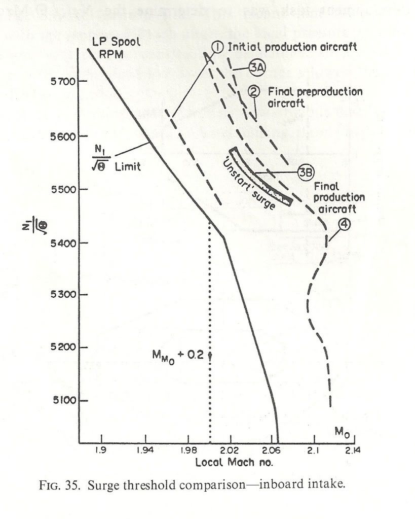 ">The next shows the surge free boundaries in sideslip and normal acceleration. You can see the zero 'g' capability Dude was enthusing over.
 ">
">
As for 'high speed stall', I don't think we ever contemplated trying it! Our requirements in 'g' capability were defined and that was it. Besides, the aircraft would fly like the proverbial stone-built outbuilding at those sorts of conditions so I don't think one would have been able to get anywhere near a stall in the conventional sense. Stall as commonly defined for subsonics (deterrent buffet) might have been another matter, but I don't remember anything.
Cheers
Last edited by CliveL; 13th Jan 2011 at 11:17 . Reason: additional explanation
24th Apr 2011, 06:28
permalink Post: 1325
SSD
I should perhaps add a bit to my first response, which was:
Although delta wings do not stall in the classic sense there is nevertheless a limit to what lift they can provide. As the AoA increases the vortices also increase in intensity, but there comes a point where the vortex flow becomes unstable and the vortex 'bursts', i.e. the circular motion degenerates into chaos and the diameter of the 'vortex' increases greatly.
The point in the vortex track at which this happens moves up towards the wing TE as AoA increases and when it reaches the TE the wing pressure distributions change and you get a break in the pitching moment curve. This happens earlier on one wing if you have sideslip, so you then tend to get a wing drop. This does not meet the airworthiness requirements so effectively vortex bursting over the wing equates to stalling.
[On another thread it has been pointed out that on the FA18 vortex bursting (off the LE extension) has caused handling problems due to interference with the fins]
I should perhaps add a bit to my first response, which was:
Quote:
| By "Stall" in this case I meant the maximum ift we could use. There was in fact a small 'hiccup' in the lift curve against AoA, but the lift went up again afterwards. However, there was a definite nose-up 'break' in the pitching moment which we took to be the limiting AoA and regarded as a 'stall' |
The point in the vortex track at which this happens moves up towards the wing TE as AoA increases and when it reaches the TE the wing pressure distributions change and you get a break in the pitching moment curve. This happens earlier on one wing if you have sideslip, so you then tend to get a wing drop. This does not meet the airworthiness requirements so effectively vortex bursting over the wing equates to stalling.
[On another thread it has been pointed out that on the FA18 vortex bursting (off the LE extension) has caused handling problems due to interference with the fins]
Last edited by CliveL; 24th Apr 2011 at 06:44 .
8th May 2013, 16:05
permalink Post: 1714
For the french speaking (or reading) people here, I just found a mine of very interesting informations about Concorde on this website:
Accueil
This site has a database of thousand of concorde flights with the following datas: Date and time of the flight, airframe used, technical and commercial crews, guests, departure/arrival airports and flight type (regular, charter world tour...).
On top of that, many infos and stories around Concorde can also be found there.
I can't resist to translate one of those stories (I'm far from being a native english speaker or a professional translator; so forgive me for the misspellings and other translation mistakes). It is a report about one of the biggest incident that happened to the prototype 001 during the flight tests:
Shock of shockwaves
We were flying with Concorde at Mach 2 since 3 month already on both side of the Channel. The prototype 001 did outstrip 002 which was supposed to be the first to reach Mach 2.
Unfortunately, a technical issue delayed 002 and Brian Trubshaw fairly let Andr\xe9 Turcat be the first to reach Mach 2 with the 001 which was ready to go.
The flight tests were progressing fast and we were discovering a part of the atmosphere that military aircrafts hardly reached before. With Concorde, we were able to stay there for hours although limited by the huge fuel consumption of the prototypes.
The Olympus engines did not reached their nominal performance yet and, most of the time, we had to turn on the reheat in supersonic cruise to maintain Mach 2.
The reheat is what we call afterburner on military aircrafts. Fuel is injected between the last compressor stage of the low pressure turbine and the first exhaust nozzle. This increases the thrust for the whole engine and its nozzle.
The 4 reheats, one for each engine, are controlled by the piano switches behind the thrust leavers on the center pedestal between the two pilots. Air was fed into the engines through 4 air intakes, one for each engine, attached 2 by 2 to the 2 engine nacelle, one under each wing. The advantage in terms of drag reduction was obvious.
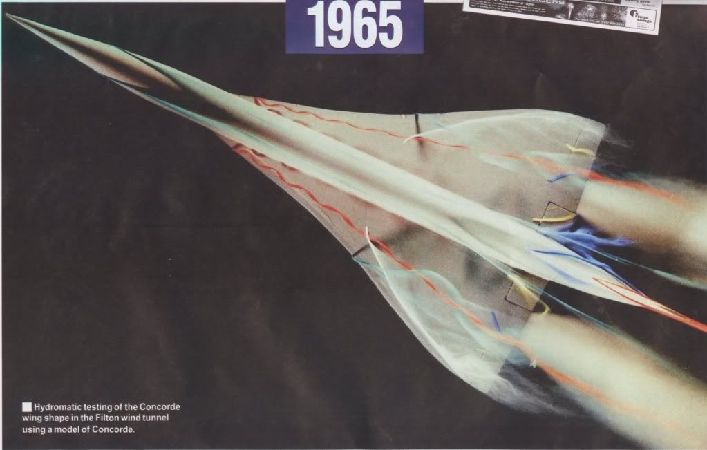
However, tests in wind tunnel showed that, at supersonic speed, if a problem happens on one engine, there was a great chance for the adjacent engine to be affected as well by the shockwave interference from one air intake to the other despite the presence the dividing wall between the two intakes. So we knew that an engine failure at mach 2 would result in the loss of 2 engines on the same side, resulting in a lateral movement leading to a strong sideslip that would likely impact the 2 remaining engines and transform the aircraft into the fastest glider in the world.
This is why an automatic anti sideslip device was developed and installed on the aircrafts.
The air intakes are very sophisticated. At mach 2, it creates a system of shockwaves that slows down the air from 600 m/sec in front of the aircraft to 200 m/sec in front of the engine while maintaining a very good thermodynamic performance. In supersonic cruise, the engines, operating at full capacity all the time, were sensitive to any perturbation and reacted violently with engine surge: the engine refusing the incoming air.
Stopping suddenly a flow of almost 200kg of air per second traveling at 600m/sec causes a few problems. As a result, a spill door was installed under the air intake and automatically opened in such event.
To control the system of shockwaves and obtain an efficiency of 0,96 in compression in the air intake, 2 articulated ramps, controlled by hydraulic jacks, are installed on the top of the air intakes in front of the engines. Each ramp is roughly the size of a big dining room table, and the 2 ramps, mechanically synchronized, move up or down following the instruction of an highly sophisticated computer that adapts the ramp position according to the mach number, the engine rating and other parameters such as skidding.
At that time, it was the less known part of the aircraft, almost only designed through calculation since no simulator, no wind tunnel, did allow a full scale test of the system.
The control of the system was analog and very complex but it was not easy to tune and we were moving ahead with a lot of caution in our test at mach 2.
On the 26th of January 1971, we were doing a nearly routine flight to measure the effect of a new engine setting supposed to enhance the engine efficiency at mach 2. It was a small increase of the rotation speed of the low pressure turbine increasing the air flow and, as a result, the thrust.
The flight test crews now regularly alternate their participation and their position in the cockpit for the pilots.
Today, Gilbert Defer is on the left side, myself on the right side, Michel R\xe9tif is the flight engineer, Claude Durand is the main flight engineer and Jean Conche is the engine flight engineer. With them is an official representative of the flight test centre, Hubert Guyonnet, seated in the cockpit's jump seat, he is in charge of radio testing.
We took off from Toulouse, accelerated to supersonic speed over the Atlantic near Arcachon continuing up to the north west of Ireland.
Two reheats, the 1 and the 3, are left on because the air temperature does not allow to maintain mach 2 without them.
Everything goes fine. During the previous flight, the crew experienced some strong turbulence, quite rare in the stratosphere and warned us about this. No problem was found on the aircraft.
We are on our way back to Toulouse off the coast of Ireland. Our program includes subsonic tests and we have to decelerate.
Gilbert is piloting the aircraft. Michel and the engineers notify us that everything is normal and ready for the deceleration and the descent.
We are at FL500 at mach 2 with an IAS of 530 kt, the maximum dynamic pressure in normal use.
On Concorde, the right hand seat is the place offering the less possibility to operate the systems. But here, we get busy by helping the others to follow the program and the checklists and by manipulating the secondary commands such as the landing gear, the droop nose, the radio navigation, comms, and some essential engine settings apart from the thrust leavers such as the reheat switches.
The normal procedure consists in stopping the reheat before lowering the throttle.
Gilbert asks me to do it. After, he will slowly reduce the throttle to avoid temporary heckler. Note that he did advise us during the training on the air intake to avoid to move the thrust leaver in case of engine surge.
As a safety measure, I shut down the reheat one by one, checking that everything goes fine for each one. Thus I switch off the reheat 1 with the light shock marking the thrust reduction. Then the 3\x85
Instantly, we are thrown in a crazy situation.
Deafening noise like a canon firing 300 times a minute next to us. Terrible shake. The cockpit, that looked like a submarine with the metallic and totally opaque visor obviously in the upper position, is shaken at a frequency of 5 oscillation a second and a crazy amplitude of about 4 to 5 G. To the point that we cannot see anymore, our eyes not being able to follow the movements.
Gilbert has a test pilot reaction, we have to get out of the maximum kinetic energy zone as fast as possible and to reduce speed immediately. He then moves the throttle to idle without any useless care.
During that time, I try, we all try to answer the question: what is going on? What is the cause of this and what can we do to stop it?
Suspecting an issue with the engines, I try to read the indicators on the centre control panel through the mist of my disturbed vision and in the middle of a rain of electric indicators falling from the roof. We cannot speak to each other through the intercom.
I vaguely see that the engines 3 and 4 seem to run slower than the 2 others, especially the 4. We have to do something. Gilbert is piloting the plane and is already busy. I have a stupid reaction dictated by the idea that I have to do something to stop that, while I can only reach a few commands that may be linked to the problem.
I first try to increase the thrust on number 4 engine. No effect so I reduce frankly and definitively. I desperately look for something to do from my right hand seat with a terrible feeling of being helpless and useless.
Then everything stops as suddenly as it started. How long did it last, 30 seconds, one minute?
By looking at the flight data records afterward, we saw that it only last\x85 12 seconds!
However, I have the feeling that I had time to think about tons of things, to do a lot of reasoning, assumption and to have searched and searched and searched\x85! It looked like my brain suddenly switched to a fastest mod of thinking. But, above all, it's the feeling of failure, the fact that I was not able to do anything and that I did not understand anything that remains stuck in my mind forever.
To comfort me, I have to say that nobody among the crew did understand anything either and was able to do anything, apart from Gilbert.
The aircraft slows down and the engine 3 that seemed to have shut down restart thanks to the auto ignition system. But the 4 is off indeed.
Michel makes a check of his instruments. He also notes that the engine 4 has shut down but the 4 air intakes work normally, which makes us feel better. After discussing together, we start to think that we probably faced some stratospheric turbulence of very high intensity, our experience in this altitude range being quite limited at that time. But nobody really believes in this explanation. Finally, at subsonic speed, mach 0.9, with all instruments looking normal, we try to restart engine 4 since we still have a long way to go to fly back to Toulouse.
Michel launches the process to restart the engine. It restarts, remains at a medium rotation speed and shuts down after 20 seconds, leaving us puzzled and a bit worried despite the fact that the instrument indicators are normal.
Gilbert then decide to give up and won't try to restart this engine anymore and Claude leaves his engineer station to have a look in a device installed on the prototype to inspect the landing gear and the engines when needed: an hypo-scope, a kind of periscope going out through the floor and not through the roof.
After a few seconds, we can hear him on the intercom:
"Shit! (stuttering) we have lost the intake number 4."
He then describes a wide opening in the air intake, the ramp seems to be missing and he can see some structural damages on the nacelle.
Gilbert reacts rapidly by further reducing the speed to limit even more the dynamic pressure.
But we don't know exactly the extent of the damage. Are the wing and the control surfaces damaged? What about engine 3?
We decide to fly back at a speed of 250 kts at a lower altitude and to divert toward Fairford where our british colleagues and the 002 are based. I inform everybody about the problem on the radio and tell them our intentions. However, I add that if no other problems occur, we will try to reach Toulouse since we still have enough fuel.
Flying off Fairford, since nothing unusual happened, we decide to go on toward Toulouse. All the possible diversion airport on the way have been informed by the flight test centre who follows us on their radar.
At low speed, knowing what happened to us and having nothing else to do but to wait for us, time passes slowly, very slowly and we don't talk much, each one of us thinking and trying to understand what happened. However, we keep watching closely after engine 3.
Personally, I remember the funny story of the poor guy who sees his house collapse when he flushes his toilets. I feel in the same situation.
Gilbert makes a precautionary landing since we don't rely much on engine 3 anymore. But everything goes fine.
At the parking, there is a lot of people waiting for us and, as soon as the engines stop, we can see a big rush toward the nacelles of the right hand side engines.
Gilbert and myself are the first to get off the plane and we are welcomed down the stairs by Andr\xe9 Turcat and Jean Franchi who came out from the crowd watching at the right hand side nacelle.
They both behave the same way, with a slow pace attitude, the same look, a mix of disbelief and frustration.
Andr\xe9 is the first to speak: "I can't believe we were not on this flight, really unlucky\x85". Yes, this flight was supposed to be just a routine flight\x85!
The condition of the nacelle is impressive. We come closer and everybody move aside for us with a look of disbelief and respect as if we were hell survivors.
The ramps of the intake 4, those 2 "dining tables", have completely disappeared leaving a hole where we can see the hydraulic jacks and the stub rod where the ramps were attached.
Indeed, only the ramps were missing, apparently ejected forward which was unbelievable knowing how fast we were flying. The ramp slipped under the nacelle causing some damages on it and on the hood of one of the elevon's servo control. Fortunately, the control did not suffer any damage.
What is left of the rear ramp seems to be blocked down inside the intake in front of the engine and we can see behind it the first blades of the compressor, or what is left of it, not much.
The engine swallowed a huge amount of metal but no vital parts of the aircraft has been damaged, no hydraulic leaks, no fuel leaks. I remembered at that time the stories of some B58 Hustler accident where the loss of an engine at mach 2 almost certainly ended with the complete loss of the aircraft. Our Concorde has only been shaken. This incident strengthened the trust I had in this plane. And I was not unhappy to have experienced this ordeal, especially when I saw the frustration on the face of Andr\xe9 Turcat and Jean Franchi.
But we had to understand what happened and how; and also why the ramp's fixing broke.
It didn't take much time to get the answers.
I unintentionally triggered the problem when shutting down the reheat of engine 3. The sudden stop of the fuel flow did of course stop the combustion and the back pressure behind the low pressure turbine. But, probably because of the modification made on the engine before the flight, the stop of the reheat has not been followed by the normal closing movement of the primary nozzle to compensate the pressure drop. So the low pressure turbine ran out of control, dragging down the low pressure compressor which reacts by surging.
Despite the opening of the spill door, the engine surge led to a sudden movement of the shockwaves in the air intake creating a surge in the intake itself. A similar surge happened in the adjacent intake 4 followed by a surge of the corresponding engine. This caused an excessive pressure above the ramps and the fixings of the intake 4 did not hold.
Since it was the first time we experienced a surge in the air intake, we had little knowledge of the stress it would create on the ramps. This led to miscalculation of the strength of the ramps's frames and they did brake.
Another mistake: instead of installing the motion detectors on the ramp itself, to make the production easier, they have been placed on the arms of the hydraulic jacks. This is why Michel R\xe9tif thought that the position of the ramps were correct. The hydraulic jacks did not suffer any damage and were still working normally even if the ramps were missing.
All the data recorded during this event helped us in redesigning the air intakes and the flight test program resumed three month later.
After this, we deliberately created dozen and dozen of air intake surge to fine tune the way to regulate them with digital calculator this time.
From now on, even if it was still very impressive, it was safe and their intensity was not comparable with what we experienced with the missing ramps.
However, a french president may kept a lasting memory of this, much later, during a flight back from Saudi Arabia. This time, I was on the left side, Gilbert on the right and Michel was still in the third seat\x85 But that's another story.
For me, the lasting impression of failing and being helpless during this incident made me wonder what a commercial pilot would have done in this situation. This plane was designed to be handled by standard commercial pilots and not only by the flight test pilots.
At that time, I was interested in taking in charge the management of a training center for the pilots of the future Airbus's clients. This event pushed me that way and I made it clear that I wanted to add the flight training on Concorde in this project. This has been agreed and I did it.
And the Concorde training program now covers the air intake surges and how to deal with them.
Jean PINET
Former test pilot
Member and former president of the Air and Space Academy
Accueil
This site has a database of thousand of concorde flights with the following datas: Date and time of the flight, airframe used, technical and commercial crews, guests, departure/arrival airports and flight type (regular, charter world tour...).
On top of that, many infos and stories around Concorde can also be found there.
I can't resist to translate one of those stories (I'm far from being a native english speaker or a professional translator; so forgive me for the misspellings and other translation mistakes). It is a report about one of the biggest incident that happened to the prototype 001 during the flight tests:
Shock of shockwaves
We were flying with Concorde at Mach 2 since 3 month already on both side of the Channel. The prototype 001 did outstrip 002 which was supposed to be the first to reach Mach 2.
Unfortunately, a technical issue delayed 002 and Brian Trubshaw fairly let Andr\xe9 Turcat be the first to reach Mach 2 with the 001 which was ready to go.
The flight tests were progressing fast and we were discovering a part of the atmosphere that military aircrafts hardly reached before. With Concorde, we were able to stay there for hours although limited by the huge fuel consumption of the prototypes.
The Olympus engines did not reached their nominal performance yet and, most of the time, we had to turn on the reheat in supersonic cruise to maintain Mach 2.
The reheat is what we call afterburner on military aircrafts. Fuel is injected between the last compressor stage of the low pressure turbine and the first exhaust nozzle. This increases the thrust for the whole engine and its nozzle.
The 4 reheats, one for each engine, are controlled by the piano switches behind the thrust leavers on the center pedestal between the two pilots. Air was fed into the engines through 4 air intakes, one for each engine, attached 2 by 2 to the 2 engine nacelle, one under each wing. The advantage in terms of drag reduction was obvious.
However, tests in wind tunnel showed that, at supersonic speed, if a problem happens on one engine, there was a great chance for the adjacent engine to be affected as well by the shockwave interference from one air intake to the other despite the presence the dividing wall between the two intakes. So we knew that an engine failure at mach 2 would result in the loss of 2 engines on the same side, resulting in a lateral movement leading to a strong sideslip that would likely impact the 2 remaining engines and transform the aircraft into the fastest glider in the world.
This is why an automatic anti sideslip device was developed and installed on the aircrafts.
The air intakes are very sophisticated. At mach 2, it creates a system of shockwaves that slows down the air from 600 m/sec in front of the aircraft to 200 m/sec in front of the engine while maintaining a very good thermodynamic performance. In supersonic cruise, the engines, operating at full capacity all the time, were sensitive to any perturbation and reacted violently with engine surge: the engine refusing the incoming air.
Stopping suddenly a flow of almost 200kg of air per second traveling at 600m/sec causes a few problems. As a result, a spill door was installed under the air intake and automatically opened in such event.
To control the system of shockwaves and obtain an efficiency of 0,96 in compression in the air intake, 2 articulated ramps, controlled by hydraulic jacks, are installed on the top of the air intakes in front of the engines. Each ramp is roughly the size of a big dining room table, and the 2 ramps, mechanically synchronized, move up or down following the instruction of an highly sophisticated computer that adapts the ramp position according to the mach number, the engine rating and other parameters such as skidding.
At that time, it was the less known part of the aircraft, almost only designed through calculation since no simulator, no wind tunnel, did allow a full scale test of the system.
The control of the system was analog and very complex but it was not easy to tune and we were moving ahead with a lot of caution in our test at mach 2.
On the 26th of January 1971, we were doing a nearly routine flight to measure the effect of a new engine setting supposed to enhance the engine efficiency at mach 2. It was a small increase of the rotation speed of the low pressure turbine increasing the air flow and, as a result, the thrust.
The flight test crews now regularly alternate their participation and their position in the cockpit for the pilots.
Today, Gilbert Defer is on the left side, myself on the right side, Michel R\xe9tif is the flight engineer, Claude Durand is the main flight engineer and Jean Conche is the engine flight engineer. With them is an official representative of the flight test centre, Hubert Guyonnet, seated in the cockpit's jump seat, he is in charge of radio testing.
We took off from Toulouse, accelerated to supersonic speed over the Atlantic near Arcachon continuing up to the north west of Ireland.
Two reheats, the 1 and the 3, are left on because the air temperature does not allow to maintain mach 2 without them.
Everything goes fine. During the previous flight, the crew experienced some strong turbulence, quite rare in the stratosphere and warned us about this. No problem was found on the aircraft.
We are on our way back to Toulouse off the coast of Ireland. Our program includes subsonic tests and we have to decelerate.
Gilbert is piloting the aircraft. Michel and the engineers notify us that everything is normal and ready for the deceleration and the descent.
We are at FL500 at mach 2 with an IAS of 530 kt, the maximum dynamic pressure in normal use.
On Concorde, the right hand seat is the place offering the less possibility to operate the systems. But here, we get busy by helping the others to follow the program and the checklists and by manipulating the secondary commands such as the landing gear, the droop nose, the radio navigation, comms, and some essential engine settings apart from the thrust leavers such as the reheat switches.
The normal procedure consists in stopping the reheat before lowering the throttle.
Gilbert asks me to do it. After, he will slowly reduce the throttle to avoid temporary heckler. Note that he did advise us during the training on the air intake to avoid to move the thrust leaver in case of engine surge.
As a safety measure, I shut down the reheat one by one, checking that everything goes fine for each one. Thus I switch off the reheat 1 with the light shock marking the thrust reduction. Then the 3\x85
Instantly, we are thrown in a crazy situation.
Deafening noise like a canon firing 300 times a minute next to us. Terrible shake. The cockpit, that looked like a submarine with the metallic and totally opaque visor obviously in the upper position, is shaken at a frequency of 5 oscillation a second and a crazy amplitude of about 4 to 5 G. To the point that we cannot see anymore, our eyes not being able to follow the movements.
Gilbert has a test pilot reaction, we have to get out of the maximum kinetic energy zone as fast as possible and to reduce speed immediately. He then moves the throttle to idle without any useless care.
During that time, I try, we all try to answer the question: what is going on? What is the cause of this and what can we do to stop it?
Suspecting an issue with the engines, I try to read the indicators on the centre control panel through the mist of my disturbed vision and in the middle of a rain of electric indicators falling from the roof. We cannot speak to each other through the intercom.
I vaguely see that the engines 3 and 4 seem to run slower than the 2 others, especially the 4. We have to do something. Gilbert is piloting the plane and is already busy. I have a stupid reaction dictated by the idea that I have to do something to stop that, while I can only reach a few commands that may be linked to the problem.
I first try to increase the thrust on number 4 engine. No effect so I reduce frankly and definitively. I desperately look for something to do from my right hand seat with a terrible feeling of being helpless and useless.
Then everything stops as suddenly as it started. How long did it last, 30 seconds, one minute?
By looking at the flight data records afterward, we saw that it only last\x85 12 seconds!
However, I have the feeling that I had time to think about tons of things, to do a lot of reasoning, assumption and to have searched and searched and searched\x85! It looked like my brain suddenly switched to a fastest mod of thinking. But, above all, it's the feeling of failure, the fact that I was not able to do anything and that I did not understand anything that remains stuck in my mind forever.
To comfort me, I have to say that nobody among the crew did understand anything either and was able to do anything, apart from Gilbert.
The aircraft slows down and the engine 3 that seemed to have shut down restart thanks to the auto ignition system. But the 4 is off indeed.
Michel makes a check of his instruments. He also notes that the engine 4 has shut down but the 4 air intakes work normally, which makes us feel better. After discussing together, we start to think that we probably faced some stratospheric turbulence of very high intensity, our experience in this altitude range being quite limited at that time. But nobody really believes in this explanation. Finally, at subsonic speed, mach 0.9, with all instruments looking normal, we try to restart engine 4 since we still have a long way to go to fly back to Toulouse.
Michel launches the process to restart the engine. It restarts, remains at a medium rotation speed and shuts down after 20 seconds, leaving us puzzled and a bit worried despite the fact that the instrument indicators are normal.
Gilbert then decide to give up and won't try to restart this engine anymore and Claude leaves his engineer station to have a look in a device installed on the prototype to inspect the landing gear and the engines when needed: an hypo-scope, a kind of periscope going out through the floor and not through the roof.
After a few seconds, we can hear him on the intercom:
"Shit! (stuttering) we have lost the intake number 4."
He then describes a wide opening in the air intake, the ramp seems to be missing and he can see some structural damages on the nacelle.
Gilbert reacts rapidly by further reducing the speed to limit even more the dynamic pressure.
But we don't know exactly the extent of the damage. Are the wing and the control surfaces damaged? What about engine 3?
We decide to fly back at a speed of 250 kts at a lower altitude and to divert toward Fairford where our british colleagues and the 002 are based. I inform everybody about the problem on the radio and tell them our intentions. However, I add that if no other problems occur, we will try to reach Toulouse since we still have enough fuel.
Flying off Fairford, since nothing unusual happened, we decide to go on toward Toulouse. All the possible diversion airport on the way have been informed by the flight test centre who follows us on their radar.
At low speed, knowing what happened to us and having nothing else to do but to wait for us, time passes slowly, very slowly and we don't talk much, each one of us thinking and trying to understand what happened. However, we keep watching closely after engine 3.
Personally, I remember the funny story of the poor guy who sees his house collapse when he flushes his toilets. I feel in the same situation.
Gilbert makes a precautionary landing since we don't rely much on engine 3 anymore. But everything goes fine.
At the parking, there is a lot of people waiting for us and, as soon as the engines stop, we can see a big rush toward the nacelles of the right hand side engines.
Gilbert and myself are the first to get off the plane and we are welcomed down the stairs by Andr\xe9 Turcat and Jean Franchi who came out from the crowd watching at the right hand side nacelle.
They both behave the same way, with a slow pace attitude, the same look, a mix of disbelief and frustration.
Andr\xe9 is the first to speak: "I can't believe we were not on this flight, really unlucky\x85". Yes, this flight was supposed to be just a routine flight\x85!
The condition of the nacelle is impressive. We come closer and everybody move aside for us with a look of disbelief and respect as if we were hell survivors.
The ramps of the intake 4, those 2 "dining tables", have completely disappeared leaving a hole where we can see the hydraulic jacks and the stub rod where the ramps were attached.
Indeed, only the ramps were missing, apparently ejected forward which was unbelievable knowing how fast we were flying. The ramp slipped under the nacelle causing some damages on it and on the hood of one of the elevon's servo control. Fortunately, the control did not suffer any damage.
What is left of the rear ramp seems to be blocked down inside the intake in front of the engine and we can see behind it the first blades of the compressor, or what is left of it, not much.
The engine swallowed a huge amount of metal but no vital parts of the aircraft has been damaged, no hydraulic leaks, no fuel leaks. I remembered at that time the stories of some B58 Hustler accident where the loss of an engine at mach 2 almost certainly ended with the complete loss of the aircraft. Our Concorde has only been shaken. This incident strengthened the trust I had in this plane. And I was not unhappy to have experienced this ordeal, especially when I saw the frustration on the face of Andr\xe9 Turcat and Jean Franchi.
But we had to understand what happened and how; and also why the ramp's fixing broke.
It didn't take much time to get the answers.
I unintentionally triggered the problem when shutting down the reheat of engine 3. The sudden stop of the fuel flow did of course stop the combustion and the back pressure behind the low pressure turbine. But, probably because of the modification made on the engine before the flight, the stop of the reheat has not been followed by the normal closing movement of the primary nozzle to compensate the pressure drop. So the low pressure turbine ran out of control, dragging down the low pressure compressor which reacts by surging.
Despite the opening of the spill door, the engine surge led to a sudden movement of the shockwaves in the air intake creating a surge in the intake itself. A similar surge happened in the adjacent intake 4 followed by a surge of the corresponding engine. This caused an excessive pressure above the ramps and the fixings of the intake 4 did not hold.
Since it was the first time we experienced a surge in the air intake, we had little knowledge of the stress it would create on the ramps. This led to miscalculation of the strength of the ramps's frames and they did brake.
Another mistake: instead of installing the motion detectors on the ramp itself, to make the production easier, they have been placed on the arms of the hydraulic jacks. This is why Michel R\xe9tif thought that the position of the ramps were correct. The hydraulic jacks did not suffer any damage and were still working normally even if the ramps were missing.
All the data recorded during this event helped us in redesigning the air intakes and the flight test program resumed three month later.
After this, we deliberately created dozen and dozen of air intake surge to fine tune the way to regulate them with digital calculator this time.
From now on, even if it was still very impressive, it was safe and their intensity was not comparable with what we experienced with the missing ramps.
However, a french president may kept a lasting memory of this, much later, during a flight back from Saudi Arabia. This time, I was on the left side, Gilbert on the right and Michel was still in the third seat\x85 But that's another story.
For me, the lasting impression of failing and being helpless during this incident made me wonder what a commercial pilot would have done in this situation. This plane was designed to be handled by standard commercial pilots and not only by the flight test pilots.
At that time, I was interested in taking in charge the management of a training center for the pilots of the future Airbus's clients. This event pushed me that way and I made it clear that I wanted to add the flight training on Concorde in this project. This has been agreed and I did it.
And the Concorde training program now covers the air intake surges and how to deal with them.
Jean PINET
Former test pilot
Member and former president of the Air and Space Academy
Last edited by NHerby; 9th May 2013 at 17:24 .