24th Aug 2010, 12:02
permalink Post: 90
MEMORIES
Like so many in the Concorde family, I have millions, I'd like to share a couple here. I remember at Fairford in mid 1974, a CAA test pilot (I honestly forget the gentleman's name) was taking the British pre-production A/C 101 (G-AXDN) for a special test flight. The reason that this flight was so special was that for the first time, the CAA were going to do an acceptance flight trial of the brand new digital air intake system. This revolutionary system had been retro fitted to 101 barely a year earlier, and being a brand new (and totally unique, in electronics terms) system had been plagued with teething troubles. It was quite reasonable for any airworthiness authority to have serious misgivings about any system that was going to wave great big metal lumps around in front of the engine compressor face, and that if only a few degrees out from the commanded position out could cause the engine to 'backfire' etc.
So anyway, 101 took off and disappeared into the very blue sky and we waited, and waited, AND WAITED. (I'd only left the RAF and joined the project a few months previously, and did not want my new association with this amazing aircraft to end). I was biting my nails, drinking coffee, losing my hair... (without the help of M2V ). Anyway after about 2 1/2 hours the aircraft returned to Fairford, and everybody crowds around the crew for the debrief. A very stern faced CAA pilot looked at us all, broke into a grin and said "as far as I'm concerned gentlemen, you've got yourselves an airliner". At that point the room was a study of total happiness, blessed relief, and a need to go to the loo..... But from my point of view, I will remember those words forever.
101, which now resides at the Imperial War Museum Duxford was the fastest Concorde ever. She achieved Mach 2.23, which was an incredible irony, as Concorde can trace a large part of it's developement history back to the BAC 223, proposed SST.
As far as flying memories go, I just don't know where to start; My first ever Concorde flight was in November 1976, out of Fairford on a pre-delivery test flight on G-BOAD. (Now sadly bobbing up and down on the Hudson, next to the USS Intrepid). I was staggered how fast and high we flew (Mach 2.08, FL580). Most of my flying up to that date had been in C-130's in the RAF, at around 340 KTS and FL300; Concorde also being infinately quiter in flight than the good old Herc'. I remember a BA QA guy showing me how I could touch the skin of the aircraft at Mach 2 (You reached behind a door busstle flap, moved your hand through some insulation until you felt bare metal). OUCH!! it was hot, very hot.
But I think one of my most memorable flight memories was aboard G-BOAG, (now residing in the Boeing Museum of Flight in Seattle) returning from BKK, having stopped off to refuel in BAH. We were forced to fly subsonic over Saudi, and got caught in this amazing electrical storm, There was St Elmo's fire cracking and bubbling all over the visor panels, but just as incredible was the long blue electrical discharge coming off of the nose probe; it seemed to extend about 50' in front of the aircraft. The crime was, none of us on the F/D had a camera. Every time I bump into the captain on that day (are you reading this Ian?), we go back to remonissing about that incredible flight. Also, later on the same sector, after we had decelerated to subsonic cruise again, this time flying up the Adriatic, we had another fascinating sight: It was getting quite dark now, and here we were, travelling at Mach 0.95 at FL290, when above us was all this Mach 0.8 ish traffic at around FL330-350. All we could see were all these navigation and ant-coll' lights above us, seemingly travelling backwards. It was quite a sight. On the original BAH-BKK sector a week earlier, we flew through some of the coldest air I'd ever seen; The air was at ISA -25, and at Mach 2 our TAT was only about 85 deg's C. (You could feel the difference too; the cabin windows felt only warm-ish to the touch). The upside also of all this was that your fuel burn was much lower than usual. (The only downside of course is that your TAS is a little lower). Rolls Royce did some analysis on the flight, and were amazed at how well the propulsion systems coped with some of the temperature sheers that we encountered, sometimes 4 to 5 deg's/second. They said that the prototype AFCS had been defeated by rises of only 0.25 deg's/second ).
Not meaning to go off onto a (yet another) tangent; Negative temperature shears, very common at lower lattidudes, always plagued the development aircraft; you would suddenly accelerate, and in the case of a severe shear, would accelerate and accelerate!! (Your Mach number, quite naturaly, suddenly increased with the falling temperature of course, but because of the powerplant suddenly hitting an area of hyper-efficiencey, the A/C would physically accelerate rapidly, way beyond Mmo). Many modifications were tried to mitigate the effects of severe shears, in the end a clever change to the intake control unit software fixed it. (Thanks to this change the production series A/C would not be capable of level flight Mach numbers of any more than Mach 2.13, remembering that Mmo was set at 2.04).
There was one lovely story, involving the Shah of Iran, having one of MANY flights in a developmment aircraft. The aircraft encounterd quite a hefty series of temperature shears that plagued havoc with some Iranian F4's that were attempting to close on the Concorde, to act as an escort for the Shah. (or so the strory goes). I'm still trying to picture these F4's, on full afterburner trying to get close to a Concorde cruising away on dry power). It is said that the F4's were having such difficulties, due to their relatively crude powerplant, coping with the temperature changes, that the Concorde was ordered to slow down, 'so the escorting F4's could catch up'!! True or not, it is part of Concorde folklore.
Dude
Like so many in the Concorde family, I have millions, I'd like to share a couple here. I remember at Fairford in mid 1974, a CAA test pilot (I honestly forget the gentleman's name) was taking the British pre-production A/C 101 (G-AXDN) for a special test flight. The reason that this flight was so special was that for the first time, the CAA were going to do an acceptance flight trial of the brand new digital air intake system. This revolutionary system had been retro fitted to 101 barely a year earlier, and being a brand new (and totally unique, in electronics terms) system had been plagued with teething troubles. It was quite reasonable for any airworthiness authority to have serious misgivings about any system that was going to wave great big metal lumps around in front of the engine compressor face, and that if only a few degrees out from the commanded position out could cause the engine to 'backfire' etc.
So anyway, 101 took off and disappeared into the very blue sky and we waited, and waited, AND WAITED. (I'd only left the RAF and joined the project a few months previously, and did not want my new association with this amazing aircraft to end). I was biting my nails, drinking coffee, losing my hair... (without the help of M2V
). Anyway after about 2 1/2 hours the aircraft returned to Fairford, and everybody crowds around the crew for the debrief. A very stern faced CAA pilot looked at us all, broke into a grin and said "as far as I'm concerned gentlemen, you've got yourselves an airliner". At that point the room was a study of total happiness, blessed relief, and a need to go to the loo..... But from my point of view, I will remember those words forever.
101, which now resides at the Imperial War Museum Duxford was the fastest Concorde ever. She achieved Mach 2.23, which was an incredible irony, as Concorde can trace a large part of it's developement history back to the BAC 223, proposed SST.
As far as flying memories go, I just don't know where to start; My first ever Concorde flight was in November 1976, out of Fairford on a pre-delivery test flight on G-BOAD. (Now sadly bobbing up and down on the Hudson, next to the USS Intrepid). I was staggered how fast and high we flew (Mach 2.08, FL580). Most of my flying up to that date had been in C-130's in the RAF, at around 340 KTS and FL300; Concorde also being infinately quiter in flight than the good old Herc'. I remember a BA QA guy showing me how I could touch the skin of the aircraft at Mach 2 (You reached behind a door busstle flap, moved your hand through some insulation until you felt bare metal). OUCH!! it was hot, very hot.
But I think one of my most memorable flight memories was aboard G-BOAG, (now residing in the Boeing Museum of Flight in Seattle) returning from BKK, having stopped off to refuel in BAH. We were forced to fly subsonic over Saudi, and got caught in this amazing electrical storm, There was St Elmo's fire cracking and bubbling all over the visor panels, but just as incredible was the long blue electrical discharge coming off of the nose probe; it seemed to extend about 50' in front of the aircraft. The crime was, none of us on the F/D had a camera. Every time I bump into the captain on that day (are you reading this Ian?), we go back to remonissing about that incredible flight. Also, later on the same sector, after we had decelerated to subsonic cruise again, this time flying up the Adriatic, we had another fascinating sight: It was getting quite dark now, and here we were, travelling at Mach 0.95 at FL290, when above us was all this Mach 0.8 ish traffic at around FL330-350. All we could see were all these navigation and ant-coll' lights above us, seemingly travelling backwards. It was quite a sight. On the original BAH-BKK sector a week earlier, we flew through some of the coldest air I'd ever seen; The air was at ISA -25, and at Mach 2 our TAT was only about 85 deg's C. (You could feel the difference too; the cabin windows felt only warm-ish to the touch). The upside also of all this was that your fuel burn was much lower than usual. (The only downside of course is that your TAS is a little lower). Rolls Royce did some analysis on the flight, and were amazed at how well the propulsion systems coped with some of the temperature sheers that we encountered, sometimes 4 to 5 deg's/second. They said that the prototype AFCS had been defeated by rises of only 0.25 deg's/second ).
Not meaning to go off onto a (yet another) tangent; Negative temperature shears, very common at lower lattidudes, always plagued the development aircraft; you would suddenly accelerate, and in the case of a severe shear, would accelerate and accelerate!! (Your Mach number, quite naturaly, suddenly increased with the falling temperature of course, but because of the powerplant suddenly hitting an area of hyper-efficiencey, the A/C would physically accelerate rapidly, way beyond Mmo). Many modifications were tried to mitigate the effects of severe shears, in the end a clever change to the intake control unit software fixed it. (Thanks to this change the production series A/C would not be capable of level flight Mach numbers of any more than Mach 2.13, remembering that Mmo was set at 2.04).
There was one lovely story, involving the Shah of Iran, having one of MANY flights in a developmment aircraft. The aircraft encounterd quite a hefty series of temperature shears that plagued havoc with some Iranian F4's that were attempting to close on the Concorde, to act as an escort for the Shah. (or so the strory goes). I'm still trying to picture these F4's, on full afterburner trying to get close to a Concorde cruising away on dry power). It is said that the F4's were having such difficulties, due to their relatively crude powerplant, coping with the temperature changes, that the Concorde was ordered to slow down, 'so the escorting F4's could catch up'!! True or not, it is part of Concorde folklore.
Dude
Last edited by M2dude; 24th Aug 2010 at 15:31 . Reason: spelling (again) :-(
8th Oct 2010, 14:18
permalink Post: 534
Feathers, these are the joys of afterburning; a totally gas guzzling way of extracting some more thrust from an engine. With Concorde, at 15 degrees TAT, you got a 78% increase in take off fuel flow for, as you say, about a 6000lb increase in thrust. Normaly adding an afterburning/reheat system is a fairly complex and heavy affair; you need both the system itself plus a variable exhaust nozzle. Because Concorde already required the primary nozzle for N1 control, the addition of reheat was at least a relatively simple and lightweight afair. The original Olympus 593-22R engine was really a little lacking in terms of dry thrust, and the addition of the reheat system was deemed essential. Concorde only had a single reheat spray ring and flame-holder, military systems often have several, with a corresponding increase in thrust growth as well as a hyper increase in fuel burn.
Further development plans for the Olypus 593 included a large increase in dry thrust; the reheat being retained only for transonic acceleration. It is such a pity that it was not to be.
Dude
Further development plans for the Olypus 593 included a large increase in dry thrust; the reheat being retained only for transonic acceleration. It is such a pity that it was not to be.
Dude
24th Oct 2010, 22:18
permalink Post: 602
Consider it done Feathers.

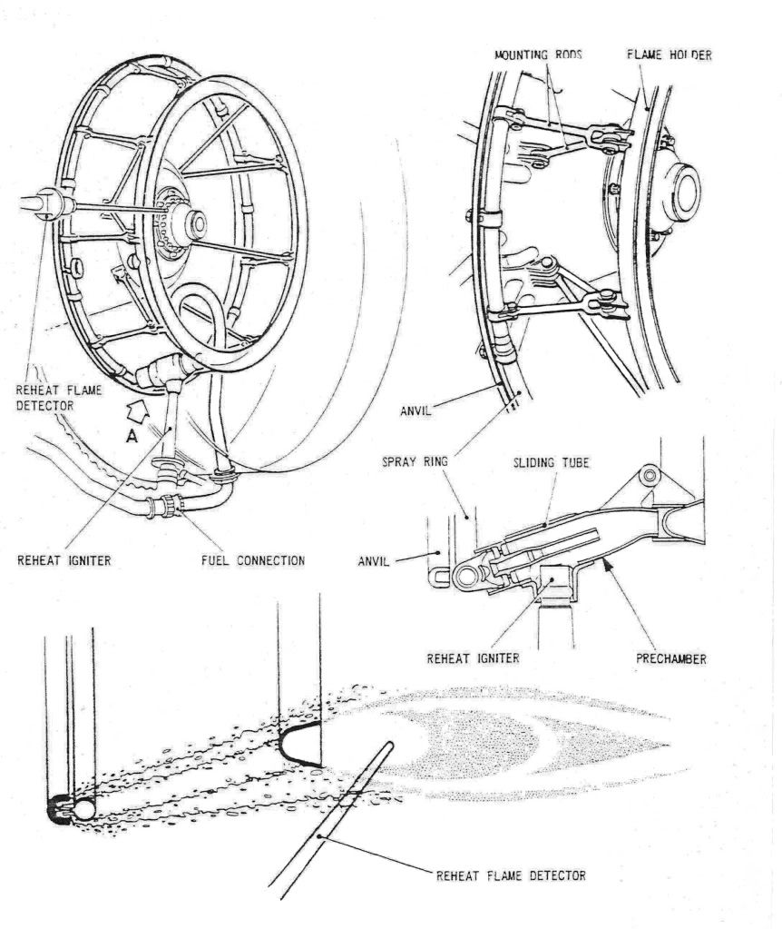
As promised, here are a few diagrams of the Concorde reheat (afterburner, for our American friends) system. The ORIGINAL design was done by SNECMA, but due to them getting into all sorts of trouble with the fuel injection system and flame stabilisation, Rolls Royce baled them out, and it became a Rolls Royce/SNECMA design. (The core engine was a 100% Rolls design, with no French input whatsoever. However some engine sub-assembles were manufactured by SNECMA).
The basic way the afterburner worked was by spraying the fuel FORWARDS intially at high pressure, against the jet stram about one inch, until it hit the anvil. . As the fuel strikes the anvil it is blown back by the jet stram and atomises, passing over the of the spray ring and the over the flame holder. The ignition operated by passing 15KV across a dual cylindrical tube, the resulting arc was 'swirlied' into the fuel stream by blowing engine 5th stage HP compressor air into the tube (there were 7 stages in all).
The key to successful ignition was a healthy spark, a good supply of air to the ignitor and accurate scheduling of fuel flow. (This was scheduled against dry engine flow as a funtion of total temperature). The other important factor (as with any afterburner) was correct and rapid operation of the exhaust nozzle. Fortunately, Concorde used it's primary nozzle for control of engine N1 anyway, so adapting this to operate as an afterburning nozzle also was a relative walk in the park, and it operated superbly.
During the light up phase of 3.5 seconds, the fuel ratio is a fixed 0.45 (ie. reheat fuel is 45% of dry fuel). After the light up phase the full scheduling commenced. As far as the FLIGHT RATING figures go (not take-off) the ratios were 0.6 at a TAT of 54 deg's C, falling linearly to 0.3 at 107 deg's C and above. (Remember that Concorde used afterburning really sparingly, just for take-off and then transonic acceleration; cut off at Mach 1.7 altogether.
Dude
27th Nov 2010, 09:24
permalink Post: 791
Nick Thomas
Oh the Rolls Royce EGT Trend Monitoring Programwas an incredible piece of kit indeed Nick. The idea was that you would input Mach, TAT, N1, N2 and EGT itself. The computer program written in BASIC (I still have a copy) would then calculate the 'brochure' EGT for those conditions (the brochure itself being based on a 127\xb0 ISA +5 day), and what the
delta
from this brochure figure actually was. This delta EGT trend over the last few flights was then plotted (it was the delta rather than the actual brochure itself that we were interested in) and if there was a sudden jump or dip from the previous flights, it was indicative of something wrong with the engine. A severe dip was indicative of compressor damage and a severe jump indicative of turbine damage. Boroscope inspections would be carried out in such a case, and the Trend Program was better than 90% accurate in terms of predicting engine problems, although these problems became less and less common as the engine design became more mature. (As a result of modifications embodied in the engine over the years). FOD damage ended up being the most common cause of headaches here.
The obvious remedy for confirmed compressor or turbine damage was to 'pull' the engine and replace it with a 'new' one; the damaged engine was then sent to Treforest in Pontypridd for overhaul. (These guys by the way did a really superb job ).
).
Best Regards
Dude
Quote:
|
Looking at the readings it appeared that he had recorded a lot more readings than just the EGT. He also added that the readings were handed to the ground engineers at the end of each flight.
It would be interesting to know what readings were recorded and the significance of them to the ground engineers. Also could the FE deduce anything form the EGT trend graph? |
The obvious remedy for confirmed compressor or turbine damage was to 'pull' the engine and replace it with a 'new' one; the damaged engine was then sent to Treforest in Pontypridd for overhaul. (These guys by the way did a really superb job
).
Best Regards
Dude
Last edited by M2dude; 27th Nov 2010 at 09:39 .
30th Nov 2010, 10:16
permalink Post: 820
Hi DavvaP, and welcome. As far as ice on the wing goes, I'm sure as any of my pilot friends here will agree that she was treated just like a subsonic in that regard; any ice or snow build up on the surfaces of the wings would not be tolerated and would have to be removed before flight. (She may have had a revolutionary wing design, but still this was a wing nonetheless
 ). She would also require pre-flight chemical anti-icing/de-icing treatment from a ground truck just like the rest, in shall we say, 'less than tropical conditions'. (Winters in Prestwick during crew base training... such fond memories


 ). As far as active ice protection on the wings, there was a highly sophisticated Lucas electrical 'spraymat' system fitted, but only the wetted areas of the wing, forward of the engines were 'covered'. Two digitall cyclic timers (CTPUs) would automatically regulate cyclic switching on and off of 115 VAC for various load areas of the wing at a time at pilot pre-selectable intervals (2, 4 or 8 seconds). Also as part of this system, there was
continuous
de-icing for certain other load areas too, so you had a mix of cyclic and continuous de-icing in operation. The whole idea here was to prevent chunks of ice entering and damaging the engines, the only other areas of this electrical de-icing system were the intake lips and side-walls and also the D Box area above the auxilliary inlet vane, built into the spill door. (This would only operate if the auxilliary inlet door itself was open). The whole shooting match would automatically switch itself off, for obvious reasons, above a TAT of 15\xb0 C. (ie. the vast majority of the flight). The only other de-icing system (apart from the galley drain masts) was on the engine inlet guide vanes, but this was purely pneumatic and again would swith itself off above 15\xb0 C.
). As far as active ice protection on the wings, there was a highly sophisticated Lucas electrical 'spraymat' system fitted, but only the wetted areas of the wing, forward of the engines were 'covered'. Two digitall cyclic timers (CTPUs) would automatically regulate cyclic switching on and off of 115 VAC for various load areas of the wing at a time at pilot pre-selectable intervals (2, 4 or 8 seconds). Also as part of this system, there was
continuous
de-icing for certain other load areas too, so you had a mix of cyclic and continuous de-icing in operation. The whole idea here was to prevent chunks of ice entering and damaging the engines, the only other areas of this electrical de-icing system were the intake lips and side-walls and also the D Box area above the auxilliary inlet vane, built into the spill door. (This would only operate if the auxilliary inlet door itself was open). The whole shooting match would automatically switch itself off, for obvious reasons, above a TAT of 15\xb0 C. (ie. the vast majority of the flight). The only other de-icing system (apart from the galley drain masts) was on the engine inlet guide vanes, but this was purely pneumatic and again would swith itself off above 15\xb0 C.
I think you will find that precious little of Concorde is now not generally available in the public domain, some control software and laws are still I would expect covered by some sort of patent. (That is why when I publiished here the engine 'E Schedule' graphs I deliberately deleted the equations for the various running lines.
Your efficiency question was a valid one; as IAS and Mach number increase the aerodynamic drag (in all it's forms) will generally increase, but the efficiency OF A WELL DESIGNED powerplant wil also increase, and Concorde was definately no exception here. The real beauty of Concorde was just HOW MUCH the powerplant efficiency increased with increasing speed and more than totally eclipsed the aerodynamic drag rise with this increasing speed. At supersonic speeds, the closer you could fly to Vmo/Mmo the lower the fuel burn was. (Especiall true at Mach 2, although the autopilot would hold you Mach 2 (ish) in Max Cruise mode, flying closer to Mmo, Mach 2.04, would save fuel, assuming the static air temoerature was low enough to sustain this). This fact (along with about a million others) produced what we all like to call 'The Magic of Concorde'
Best Regards
Dude
). She would also require pre-flight chemical anti-icing/de-icing treatment from a ground truck just like the rest, in shall we say, 'less than tropical conditions'. (Winters in Prestwick during crew base training... such fond memories
). As far as active ice protection on the wings, there was a highly sophisticated Lucas electrical 'spraymat' system fitted, but only the wetted areas of the wing, forward of the engines were 'covered'. Two digitall cyclic timers (CTPUs) would automatically regulate cyclic switching on and off of 115 VAC for various load areas of the wing at a time at pilot pre-selectable intervals (2, 4 or 8 seconds). Also as part of this system, there was
continuous
de-icing for certain other load areas too, so you had a mix of cyclic and continuous de-icing in operation. The whole idea here was to prevent chunks of ice entering and damaging the engines, the only other areas of this electrical de-icing system were the intake lips and side-walls and also the D Box area above the auxilliary inlet vane, built into the spill door. (This would only operate if the auxilliary inlet door itself was open). The whole shooting match would automatically switch itself off, for obvious reasons, above a TAT of 15\xb0 C. (ie. the vast majority of the flight). The only other de-icing system (apart from the galley drain masts) was on the engine inlet guide vanes, but this was purely pneumatic and again would swith itself off above 15\xb0 C.
I think you will find that precious little of Concorde is now not generally available in the public domain, some control software and laws are still I would expect covered by some sort of patent. (That is why when I publiished here the engine 'E Schedule' graphs I deliberately deleted the equations for the various running lines.
Your efficiency question was a valid one; as IAS and Mach number increase the aerodynamic drag (in all it's forms) will generally increase, but the efficiency OF A WELL DESIGNED powerplant wil also increase, and Concorde was definately no exception here. The real beauty of Concorde was just HOW MUCH the powerplant efficiency increased with increasing speed and more than totally eclipsed the aerodynamic drag rise with this increasing speed. At supersonic speeds, the closer you could fly to Vmo/Mmo the lower the fuel burn was. (Especiall true at Mach 2, although the autopilot would hold you Mach 2 (ish) in Max Cruise mode, flying closer to Mmo, Mach 2.04, would save fuel, assuming the static air temoerature was low enough to sustain this). This fact (along with about a million others) produced what we all like to call 'The Magic of Concorde'
Best Regards
Dude
Last edited by M2dude; 30th Nov 2010 at 12:21 .
2nd Dec 2010, 11:33
permalink Post: 823
howiehowie93
Welcome aboard and thank you for your kind words; I am so glad you enjoy our thread. You are in good company here also, many of the 'more mature' vintage Concorde people
(like me) are ex-RAF. (And some of the pilots were ex-RN also, but no one is perfect
... only joking guys).
It is a matter of pride/embarrassment for me that up to the end of 2003, I'd only ever really 'known' two aircraft; the C-130 and Concorde
.
I was really interested in some of the RB199/Olympus similarities; TBP was tried on the development aircraft for engine control TET calculation, but Rolls-Royce were unhappy with the performance and abandoned TBP in favour of indirectly computing TET as a function of T1 (intake TAT) and EGT (T7). (And this meant the removal of the four TBP amplifiers too... we had even more black boxes then.
As for the three 'control amps' you were speaking of, I'm 99% sure that A/C 101, G-AXDN still does have the units you described fitted. The ECUs (or ECAs as they were sometimes called) were a highly complex analog control unit built by Ultra Electronics. They could be quite a headache sometimes in terms of reliability, but would generally perform flawlessly in terms of engine control. As with any analog box, control law changes in the field were not too straightforward and a soldering iron was the flight test engineers best friend here. The Reheat Amp was built by ELECMA (the electronics arm of SNECMA) and unlike some of the other components in the reheat system, was a beautifully designed and constructed unit. Very few reheat failures (and there were many) were attributed to the 'box' itself. The main fragility with the reheat system was the ignition system used (a 20 KV swirl ignitor, which you will see is covered previously in the thread). We (BA/RR) were seriously looking at one point of investigatng the use of 'hot streak' injection as a backup ignition source, which I believe was used in the 199 (?), but it unfortunately never happened. The Plessey DECU that was tried on A/C 202 (G-BBDG) DID combine main engine control and reheat, but unfortunately was never taken up for the production A/C, and so we were left withe the '3 AMPS' as you so eloquently describe. We had a total of THIRTY ONE control units associated with powerplant control on Concorde; might be a little different now methinks
]
Thanks for some of the fascinating engine history snippets you shared with us, although purists might regard it as being 'off topic' I personally think this rather unique thread is all the better for your contribution here,
I think it is great that you are working with industrial Olympuses, all part of the family tree. I will dig out the verboten sustained N1 speed band for the 593, it certainly WAS a fact though.
Thanks from all of us for your contribution here Howie, keep on posting.
Regards
Dude
27th Apr 2012, 17:37
permalink Post: 1602
1) Effectively it was (not the skin, but the TAT probe. The highest temp rise would be at the stagnation point so one can be confident that TAT is a realistic answer for max skin temp).
2) AFAIK pretty standard:
Q from pitots
S from statics
T from temp probe
Modified by ADC for position error. It's possible that ADC used beta inputs and I'm sure it used alpha inputs to achieve this.
2) AFAIK pretty standard:
Q from pitots
S from statics
T from temp probe
Modified by ADC for position error. It's possible that ADC used beta inputs and I'm sure it used alpha inputs to achieve this.
27th Apr 2012, 20:29
permalink Post: 1606
Quote:
|
1) Effectively it was (not the skin, but the TAT probe. The highest temp rise would be at the stagnation point so one can be confident that TAT is a realistic answer for max skin temp).
2) AFAIK pretty standard: Q from pitots S from statics T from temp probe Modified by ADC for position error. It's possible that ADC used beta inputs and I'm sure it used alpha inputs to achieve this. |
1) So there is a direct temp reading, from the TAT probe. But where is TAT probe? Is it in the needle nose probe that also measures pitot/static for the intake computers? And how many TAT sensors are there (failure of a single one if that's all there is would not be good)?
2) Mach comes from dynamic pressure (pitots), from static ports, and from temp. But what temp? OAT perhaps?
27th Apr 2012, 22:06
permalink Post: 1608
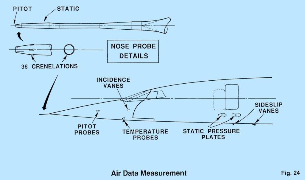
SSD:- this answers your question on where the TAT probes were located. Strictly, you don't need temperature to calculate Mach as it is independent of temperature when expressed in EAS (or CAS) terms.
Shane:
The "crown modifications" were external straps to be applied to the upper part of the fuselage to extend its life in those areas which had been designed to safe life concepts - basically the Aerospatiale bits since BAe designed their bits according to damage tolerance rules. It wasn't a small job, but I'm afraid I can't tell you how many aircraft were modified.
28th Apr 2012, 10:15
permalink Post: 1610
So far as I know, they were standard TAT measurement instruments, so they gave Total Air Temperature directly.
There was, so far as I recall, no measure of skin temperature - the aircraft limit (Tmo) was simply based on a measured TAT of 400 degK. The implied limits on skin temperature at various points were built into the design cases.
There was, so far as I recall, no measure of skin temperature - the aircraft limit (Tmo) was simply based on a measured TAT of 400 degK. The implied limits on skin temperature at various points were built into the design cases.
28th Apr 2012, 11:47
permalink Post: 1611
No part of the skin will be warmer than the TAT probe, if that helps......
28th Apr 2012, 20:53
permalink Post: 1612
Here's the cockpit temp gauge I photgraphed today:

So the TAT probe provides TAT (obviously) which effectively is skin temp (as evidenced by the TMO legend of 127C just below the TAT window?).
(TAT being static air temp plus the temp due adiabatic heating).
So the TAT probe provides TAT (obviously) which effectively is skin temp (as evidenced by the TMO legend of 127C just below the TAT window?).
(TAT being static air temp plus the temp due adiabatic heating).
Last edited by Shaggy Sheep Driver; 28th Apr 2012 at 21:14 .
28th Apr 2012, 22:25
permalink Post: 1615
Quote:
|
http://i1080.photobucket.com/albums/.../SkinTemps.jpg
Not exactly skin temperature, just the maximum temperature on the nose. The rest of the aircraft was cooler. |
So TAT is skin temp at the probes, which are rearward of the hottest skin according to that diagram. Was there a 'compensation' built into the TAT readout to account for the relatively rearward position of the TAT probes?
And.. How was static temp readout derived?
Sorry to keep asking, but I really want to understand this!
Thanks.
Last edited by Shaggy Sheep Driver; 28th Apr 2012 at 22:45 .
29th Apr 2012, 08:11
permalink Post: 1616
Quote:
|
So TAT is skin temp at the probes, which are rearward of the hottest skin according to that diagram. Was there a 'compensation' built into the TAT readout to account for the relatively rearward position of the TAT probes?
And.. How was static temp readout derived? |
They are mounted off the skin and in freestream, so they measure the same temperature as would a probe on the nose.
Somewhere near the nose (not exactly on it, as the aircraft flies with a small AoA) there will be a 'stagnation' streamline where the oncoming air is brought to rest. At this point the skin temperature will be equal to the stagnation temperature (TAT). Behind that it gets more complicated! The skin temperature would depend on SAT, local Mach No, local skin friction coefficient (Mach and Re dependent, so varies with distance from nose), amount of heat radiated into space (paint colour!) and the amount of structure available to conduct heat away from the skin into the fuel (so roughly varying with thickness/chord and fuel distribution perhaps?
Static temperature and total temperature are related by a simple expression:
TAT = SAT *(1+0.2m^2) all in deg K
So in the troposphere at ISA +5 and Mach 2, SAT = 222 and TAT = 400.
3rd May 2012, 15:13
permalink Post: 1621
Quote:
|
Er - no, the TAT probes measure just what they say Total Air Temperature.
They are mounted off the skin and in freestream, so they measure the same temperature as would a probe on the nose. Somewhere near the nose (not exactly on it, as the aircraft flies with a small AoA) there will be a 'stagnation' streamline where the oncoming air is brought to rest. At this point the skin temperature will be equal to the stagnation temperature (TAT). Behind that it gets more complicated! The skin temperature would depend on SAT, local Mach No, local skin friction coefficient (Mach and Re dependent, so varies with distance from nose), amount of heat radiated into space (paint colour!) and the amount of structure available to conduct heat away from the skin into the fuel (so roughly varying with thickness/chord and fuel distribution perhaps? |
The temperature shown in the top window of the flight deck gauge is TAT, with the legend 'TMO 128C' beneath it. So the aircraft was flown with reference to TAT, and provided TAT was no greater than 128C then the skin rearward of the stagnation point would be <128C?
15th May 2012, 10:03
permalink Post: 1631
The TAT thing
Quote:
|
OK, so the skin temperature at the stagnation point will be equal to TAT. This can be taken as the hottest part of the aircraft (behind it, the skin temperature will be less than the TAT).
The temperature shown in the top window of the flight deck gauge is TAT, with the legend 'TMO 128C' beneath it. So the aircraft was flown with reference to TAT, and provided TAT was no greater than 128C then the skin rearward of the stagnation point would be <128C? |
MACH 0.5 . ISA -5: TAT = -50.6 \xb0 C . ISA: TAT = -45.3 \xb0 C. ISA +5 TAT = -40 \xb0 C
MACH 1.0 . ISA -5: TAT = -18.5 \xb0 C . ISA: TAT = -12.5 \xb0 C. ISA +5 TAT = -6.5 \xb0 C
MACH 1.5 . ISA -5: TAT = 34.8 \xb0 C . ISA: TAT = 42 \xb0 C. ISA +5 TAT = 49.3 \xb0 C
MACH 2.0 . ISA -5: TAT = 109.5 \xb0 C . ISA: TAT =118.6 \xb0 C. ISA +5 TAT = 127.6 \xb0 C
Hopefully it all makes a little more sense with some 'real' numbers. You can see that as Mach Number increases the gap between SAT and TAT increases hugely. The Mach 2, ISA +5 case was particularly significant for Concorde, as it breached the 127 \xb0 C/400 \xb0 K airframe temperature limit (TMO) and Mach Number would therefore be automatically reduced by the autopilot. (An overspeed warning would be generated at TMO +7 (134. \xb0 C). Fortunately sustained ISA +5 or above conditions were relatively rare over the North Atlantic but not unheard of either.
Last edited by M2dude; 16th May 2012 at 23:06 . Reason: ISA+5 Typo