13th Aug 2010, 09:45
permalink Post: 2
Hi Stilton, that is a question that we all used to ask ourselves; not having an APU was a major pain in the butt for the fleet, particularly at charter destinations, where air start trucks, GPU's and air conditioning trucks would all have to be pre-arranged.
One problem with 'Conc' was always one of weight, (for every extra pound you carried, another pound of fuel was required) so any APU installation would have to have been light, and worth the extra weight. But the main problem was one of 'where to put the darned thing. The only suitable space available for an APU was in the tailcone, aft of the tail wheel. Now a ready supply of fuel would have been available either from the aft trim tank, #11, or from one of the two trim galleries. (For stability reasons, tank 11 was invariably left empty during ground transits). The real crunch however, was how to arrange pneumatic services from an APU: Tank 11 was directly forward of the tailcone, so this would have meant either ducting the pneumatics THROUGH the fuel tank (not a particularly good idea ) or externally around the fuselage, which would have been 'draggy' to say the least.
You could still have had an APU powering hydraulics, and in essence electrics too (the emergency generator was powered from the Green System), but without pneumatics for engine starting and air conditioning, it would really have been a waste of weight. Still, it really is a shame that there was no APU.
Historically, there were 'sort of' aux power units fitted to development aircraft: The prototypes had two GTS's (Gas Turbine Starters), one in each nacelle pair, that could start the engines without an air start truck, but these never saw the light of day in later aircraft. The most unusual unit of all was the MEPU (Monogol Emergency Power Unit), located in the tail cone. This was manufactured by Sundstrand, and was fitted to all of the development aircraft. (A derivation of a unit fitted to the X-15!!). The idea was that if you had a four-engined flameout at Mach 2, this thing would fire up, power Green and Yellow hydraulics (plus the emergency generator, again from the Green system), and give you power and control down to a safe relight altitude. The MEPU was powered by Hydrazine rocket fuel (unbelievably unstable) and I seem to remember that the thing would run for about 8 minutes. There was no way that this monstrosity would ever be acceptable on a commercial aircraft, and so a conventional RAT was developed by Dowty for the production aircraft. (Also, the windmilling engines would give you full electrics down to Mach 1.1, and Hydraulics down to about Mach 0.7, so the thing had little practical use when supersonic anyway).
I hope this extended blurb helps answer your query Stilton.
One problem with 'Conc' was always one of weight, (for every extra pound you carried, another pound of fuel was required) so any APU installation would have to have been light, and worth the extra weight. But the main problem was one of 'where to put the darned thing. The only suitable space available for an APU was in the tailcone, aft of the tail wheel. Now a ready supply of fuel would have been available either from the aft trim tank, #11, or from one of the two trim galleries. (For stability reasons, tank 11 was invariably left empty during ground transits). The real crunch however, was how to arrange pneumatic services from an APU: Tank 11 was directly forward of the tailcone, so this would have meant either ducting the pneumatics THROUGH the fuel tank (not a particularly good idea
) or externally around the fuselage, which would have been 'draggy' to say the least.
You could still have had an APU powering hydraulics, and in essence electrics too (the emergency generator was powered from the Green System), but without pneumatics for engine starting and air conditioning, it would really have been a waste of weight. Still, it really is a shame that there was no APU.
Historically, there were 'sort of' aux power units fitted to development aircraft: The prototypes had two GTS's (Gas Turbine Starters), one in each nacelle pair, that could start the engines without an air start truck, but these never saw the light of day in later aircraft. The most unusual unit of all was the MEPU (Monogol Emergency Power Unit), located in the tail cone. This was manufactured by Sundstrand, and was fitted to all of the development aircraft. (A derivation of a unit fitted to the X-15!!). The idea was that if you had a four-engined flameout at Mach 2, this thing would fire up, power Green and Yellow hydraulics (plus the emergency generator, again from the Green system), and give you power and control down to a safe relight altitude. The MEPU was powered by Hydrazine rocket fuel (unbelievably unstable) and I seem to remember that the thing would run for about 8 minutes. There was no way that this monstrosity would ever be acceptable on a commercial aircraft, and so a conventional RAT was developed by Dowty for the production aircraft. (Also, the windmilling engines would give you full electrics down to Mach 1.1, and Hydraulics down to about Mach 0.7, so the thing had little practical use when supersonic anyway).
I hope this extended blurb helps answer your query Stilton.
16th Aug 2010, 16:37
permalink Post: 14
Just looked up the MEPU in the 01 AFM, and indeed it's located in the tail cone. I'll scan the page this evening.
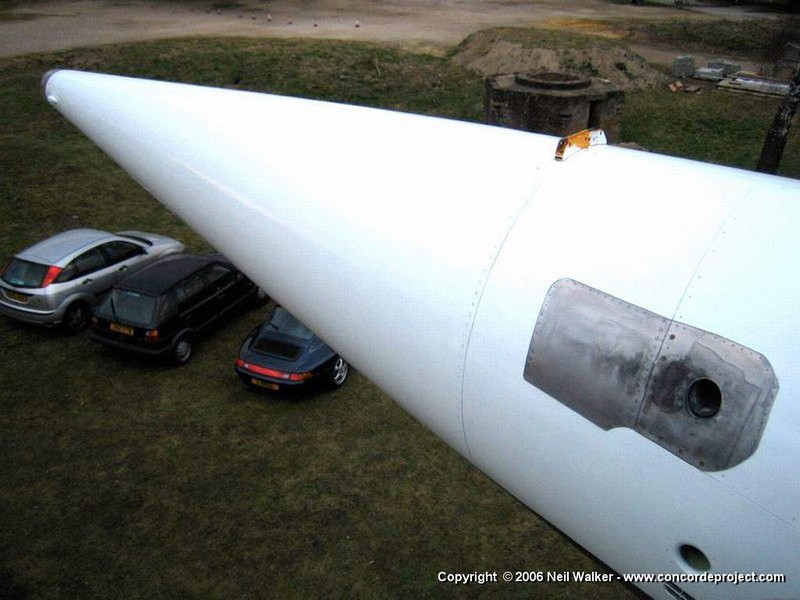
In the meantime, here's the MEPU exhaust in the tailcone of Delta Golf, courtesy of Neil Walker.
CJ
In the meantime, here's the MEPU exhaust in the tailcone of Delta Golf, courtesy of Neil Walker.
CJ
17th Aug 2010, 14:33
permalink Post: 17
M2dude,
Nice set of photos of "The Thing" here :
MEPU at MAE at le Bourget .
This one is at the Air and Space Museum at Le Bourget, near Paris. My guess is that is was a spare, since the manufacturing date is 1973. 'SA flew in January '73 and 'SB in December '73.
IIRC, Delta Golf arrived at Brooklands with the MEPU still in place; I might have a photo.
As to the installation, we're obviously thinking along the same lines....
However, there were already several conduits through tank 11, such as hydraulics for the tail wheel, various electrics, and the 'backbone' fuel manifolds, that ended at the fuel jettison port in the tailcone.
A couple of fairly substantial air ducts would only have displaced a few hundred kgs of fuel at the most, out of the more than 10,000 kgs in tank 11.
And yes, of course, the whole point of the APU would be to have independent ground start and ground airco available, so clearly an APU would have been bigger and heavier than the MEPU (which was only just over 80 lbs), plus the problem of the air intake and bigger exhaust.
I'd have to get the drawings out to see how easy or difficult it would have been to fit one in the available space.
Since the tailcone was BAC, and both 214 and 216 were built at Filton, I wonder if anybody there still remembers?
23rd Aug 2010, 08:28
permalink Post: 77
Biggles78
This is the minimum Mach number that can be flown with the existing CG. (which would be around 59%). Just as the CG indicator (not shown in this photo) gave minimum and maximum CG for a given Mach number, the Machmeter gave a reciprical indication also). You can also see that as the aircraft is not flying at Vmo any more, being at Mach 2 cruise, that the VSI pointer is now away from the orange and black Vmo bug. At our 'not so coffin corner', now that the aircraft is at maximun alllowable altitude, Vmo would naturaly coincide with Mmo; the orange and black Mmo bug being shown at Mach 2.04. This really superb photo taken by Bellerophon gives a graphic illustration of what the panels looked like at Mach 2. Note that the with the TCAS VSI Concorde retained it's original linear VSI also. (Miust have beeen the only aircraft flying with FOUR VSIs. (The originals had to be retained due to the fact that the autopilot Vert' Speed Mode error was derived from the indicator itself. As far as TCAS goes, R/As werer inhibited above FL300 (on acceleration this would coincide with the aircraft becoming supersonic, and the mfrs would not countenance the aircraft doing extreme manoeuvrs as a result of TCAS RAs at supersonic speeds).
The tail wheel was lowered for all 'normal' gear cycles (not stby lowering of free-fall). It was designed to protect the bottom the nacelles in the case of over-rotation, but in practical terms the thing was a waste of space (and weight) and a simple tail skid (used on the prototypes) would have sufficed. Any time that the tail wheel contacted the ground, it would ALWAYS collapse, damage the tailcone structure and in fact aforded no protection whatsoever. Fortunately these events were EXTREMELY few and far between. The biggest problem with the tail wheel was a major design flaw: On gear retraction the assembly would retract in sequence with the nose and main gear, and as it entered the opening in the tailcone, it would release over-centre locks that were holding the spring-loaded doors open. The doors would then firmly spring shut behind the gear assembly and finish the job. UNFORTUNATELY this was a very poor design; if for any reason one of the two doors had not gone over-centre on the previous gear lowering, it would be struck by the retracting tail wheel gear and cause structural damage to the local skin area, that would have to have a repair done. Unfortunately these events were not quite so rare, and several measures were tried to reduce the chance of this happening. Although not a safety issue, it was an issue that was a total pain. (As a matter of interest, G-BOAC had this happen on one of it's first test flights out of Fairford in 1975).
Nick Thomas
As ChristiaanJ said, the last two BA aircraft WERE lighter than the others, and would be preferred aircraft for certain charters. But that is not to say that any aircraft could not happily do ANY sector. We fortunately had no distorted airframes in the British fleet, so this was never an issue. There was very little spread, regarding fuel consumption between different engines; one of the best parts about the Olympus 593 was that it hade very little performance deterioration with time, it was an amazing piece of kit.
Time on wing for the engines was a real variable. Each engine was built up of modules, each one of these had a seperate life. In the early days of operation, time on wing was quite poor, and MANY engines would be removed on an attrition basis. One of the early failure problem was the fuel vapourisers inside the combustion chamber were failing, taking bits of turbine with it!! A Rolls Royce modification that completely changed the design of the vapouriser not only solved the problem completely, but also increased the performance of the engine. As the engine matured in service time on wing greatly improved, and in service failures became a thing of the past. A 'trend analysis' was done after each protracted supersonic flight, where engine parameters were input into a propiatry RR computer program, that was able to detect step changes in the figures, and if this were the case, more boroscope inspections were carried out. The OLY time on wing was nothing compared to the big fan engines, but the conditions that it operated under bore no comparison. Not really sure about absolute figures on this one Nick, I'll ask one of my Rolls Royce friends and see if I can find a figure.
Quote:
| What is the Yellow Arc on the Mach metre that starts at about M1.12? |
Quote:
| The center rear fuselage gear unit, what was that for? I have seen it deployed on many occasions but I can't for the life of me remember if it was during T/O or LDG however it didn't seem to be extended every time the aeroplane flew. Was this used during loading so she didn't accidently "rotate" at the ramp or to avoid a tailstrike during LDG? I can't imagine an over rotate during T/O. |
Nick Thomas
Quote:
| As regards fuel burn: was there any difference between each indvidual airframe and if so was it significant enough to be considered when calculating the trip fuel? Also did different engines also have slightly different fuel consumption? |
Quote:
| Whilst on the subject of engines, I just wondered how many were required to keep the BA Concorde fleet flying? What sort of useful life could be expected from the engines? |
Last edited by M2dude; 19th Jan 2011 at 13:42 .
15th Sep 2010, 17:39
permalink Post: 367
The blue area at the front is the MEPU firewall. My main memories of the MEPU on Concorde (Apart from the fact that it was always breaking down)was the awful STINK of the Hydrazine insode the tailcone. (Made your eyes water). Good photo though.
Dude
Dude
16th Sep 2010, 08:35
permalink Post: 370
BlueConcorde
As far as the MEPU went, yes there was just mainly empty space inside the tailcone, Aside from the tail wheel assembly there was just the power supply for the tail beacon as well as the fuel vent and jettison pipes. (On the forward bulkhead there were pumps and valves for tank 11). Having this great empty void did create problems in the early days of airline operation; there were some internal structural failures inside the tailcone (a low stressed area, so it was never serious). These failures were quickly attributed to acoustic fatigue inside the tailcone, due to resonance with engine and aerodynamic noise. This never occurred during any of the development flying; the prototypes and aircraft 1010 had a far smaller tailcone anyway, and aircraft 102, 201 and 202 had the bulk of the MEPU assembly complete with Hydrazine tank to fill up most of the void. The fix to the cracking problems was both very simple and quick to implement, and it never became a big deal. The MEPU, as has been mentioned a few times previous, was both useless and unsafe as far as a commercial aircraft goes; being replaced by a ram air turbine.
It's funny, but this is how this wonderful thread started over one month ago by stilton , I for one am so glad that it has both progressed and diversified the way that it has.
As far as charters go I'll leave it up to EXWOK or one of the other guys to answer, as far as flight planning goes. Thanks for your comments BlueConcorde, they always took a ground engineer on RTW charters, and although I never had the pleasure of directly participating in one (although I was on the end of a phone several times when problems occurred en-route)I WAS due to go in 2000, but tragic events in Paris caused that charter to be cancelled. I was however lucky enough to participate in various other charters, my most memorable one was in October 1991, when the World Bank chartered Concorde to Bangkok. The most amazing thing about RTW charters (or earth orbiters, as I would call them) was that the aircraft often returned to London with only a very small handfull of minor defects. The thing about Concorde was the more that she flew, the happier she was, and less likely to catch a cold.
PS. oops, EXWOK is already 'there'
Dude
20th Sep 2010, 17:28
permalink Post: 427
Quote:
|
Originally Posted by
DozyWannabe

I may stand corrected - was Fox-Bravo simply unbolted for the canal trip?
|
You may have to search a bit, but somewhere on the net there is a huge photoalbum of the journey, interesting from beginning to end.
Oh, and I hope for you that nobody German reads this... it was not a 'canal', but the Rhine!
CJ
18th Nov 2010, 00:32
permalink Post: 719
Mr Vortex
First of all, 'welcome aboard'; I'll do my best to answer your queries.
The area of the primary nozzle Aj, was varied for 2 'primary' purposes :
:
a) To act as a military type 'reheat' or 'afterburning' nozzle; opening up to control the rise in jet pipe pressure P7, as reheat is in operated.
b) To match the INLET TOTAL TEMPERATURE RELATED (T1) speed of the LP compressor N1 to the HP compressor N2 against a series of schedules, ensuring easch spool is as close as safely possible to its respective surge boundary, (with a constant TET, see below) and therefore at peak efficiency.
Now, in doing this a complex set of variables were in place. As the nozzle is opened there is a REDUCED pressure and temperature drop across the LP turbine. This has the effect of enabling a HIGHER N1,as less work is being done by the turbine. Also the change (in this case a decrease) in the temperature drop across the turbine will obviously affect the turbine entry temperature, TET. A closing down of the nozzle would obviously have the opposite effect, with a DECREASE in N1 and an INCREASE in TET.
In practice at a given T1 there was always an ideal N1 versus N2 on the control schedule (known as the E Schedule), the TET staying more or less constant from TAKE-OFF to SUPERSONIC CRUISE!!
As far as noise abatement went; when reheat was cancelled and power reduced after take-off, an E Schedule known as E Flyover was automatically invoked. This had the effect of driving the primary nozzle nearly wide open, reducing both the velocity of the jet efflux and in essence the noise below the aircraft.
The real beauty of this primary nozzle system was that it really did not care if the engine was operating dry or with afterburning ('it' did not even know). P7 was controlled against a varying compressor outlet pressure, the variable being controlled by a needle valve operated by the electronic engine controller. (If this is unclear I can post a diagram here that shows this control in action).
As soon as I receive back the majority of my technical notes that I have out on long-term loan (I've requested their return) I will post a schematic here. But for now; The tanks were vented to atmosphere via tandem vent galleries, the two vents openings being on the left hand side of the tail-cone. At an absolute static pressure of 2.2 PSIA (around 44,000') twin electrically operated vent valves, also in the tail-cone, would automatically close; the tanks now being pressurised via a small NACA duct on the right side of the fin. A tank pressure of around 1.5 PSIG was maintained by the action of a small pneumatic valve at the rear of the aircraft. There was massive protection built in to guard against over-pressure (eg. if a tank over-filled in cruise).
I hope this answers some of your queries
Best Regards
Dude
Quote:
|
1. I've heard that Concorde use the primary nozzle to modulate the noise and the speed of the N1 compressor. How does it work? and does it help to reduce the noise a lot?
2.Another thing about Primary nozzle. If i recall it correctly, the primary nozzle can also use to control the Inlet Turbine temperature. Is that true? How is that work |
The area of the primary nozzle Aj, was varied for 2 'primary' purposes
:
a) To act as a military type 'reheat' or 'afterburning' nozzle; opening up to control the rise in jet pipe pressure P7, as reheat is in operated.
b) To match the INLET TOTAL TEMPERATURE RELATED (T1) speed of the LP compressor N1 to the HP compressor N2 against a series of schedules, ensuring easch spool is as close as safely possible to its respective surge boundary, (with a constant TET, see below) and therefore at peak efficiency.
Now, in doing this a complex set of variables were in place. As the nozzle is opened there is a REDUCED pressure and temperature drop across the LP turbine. This has the effect of enabling a HIGHER N1,as less work is being done by the turbine. Also the change (in this case a decrease) in the temperature drop across the turbine will obviously affect the turbine entry temperature, TET. A closing down of the nozzle would obviously have the opposite effect, with a DECREASE in N1 and an INCREASE in TET.
In practice at a given T1 there was always an ideal N1 versus N2 on the control schedule (known as the E Schedule), the TET staying more or less constant from TAKE-OFF to SUPERSONIC CRUISE!!
As far as noise abatement went; when reheat was cancelled and power reduced after take-off, an E Schedule known as E Flyover was automatically invoked. This had the effect of driving the primary nozzle nearly wide open, reducing both the velocity of the jet efflux and in essence the noise below the aircraft.
The real beauty of this primary nozzle system was that it really did not care if the engine was operating dry or with afterburning ('it' did not even know). P7 was controlled against a varying compressor outlet pressure, the variable being controlled by a needle valve operated by the electronic engine controller. (If this is unclear I can post a diagram here that shows this control in action).
Quote:
3.Finally, does some one have a schematic or the fuel vent system?

|
I hope this answers some of your queries
Best Regards
Dude
8th Apr 2011, 03:42
permalink Post: 1278
there were already several conduits through tank 11, such as hydraulics for the tail wheel, various electrics, and the 'backbone' fuel manifolds, that ended at the fuel jettison port in the tailcone.
A couple of fairly substantial air ducts would only have displaced a few hundred kgs of fuel at the most, out of the more than 10,000 kgs in tank 11.
A couple of fairly substantial air ducts would only have displaced a few hundred kgs of fuel at the most, out of the more than 10,000 kgs in tank 11.
10th Jun 2015, 04:28
permalink Post: 1890
Here's a link to the six development aircraft, with pix of all of them.
CONCORDE SST : PROTOTYPE FLEET
Several had different paint schemes throughout their history, so that may not be definitive. But there are variations that can narrow down which might be in your painting: long or short tailcone, and small window or large greenhouse cockpit visor.
Three of the six are British G registrations, and three have French F-numbers. Three have "...01" production numbers. As ChristiaanJ says, none would be registered "1-GEE" - but that might have been something added for a specific test flight or for some other reason unrelated to registration. They were repainted occasionally (including one painted in BA livery on one side and AF livery on the other, for a time.)