23rd Aug 2010, 13:20
permalink Post: 80
The reason that #4 engine was limited to 88% N1 on take-off was an interesting one, down to something known as 'foldover effect'. This was discovered during pre-entry into service trials in 1975, when quite moderate levels of first stage LP compressor vibrations were experienced at take-off, but on #4 engine only. Investigations revealed that the vibrations were as the result of vorticies swirling into #4 intake, in an anti-clockwise direction, coming off the R/H wing leading edge. As the engine rotated clockwise (viewed from the front) these vorticies struck the blades edgewise, in the opposite DOR, thus setting up these vibrations. The vorticies were as a result of this 'foldover effect', where the drooping leading edge of the wing slightly shielded the streamtube flowing into the engine intake. #1 engine experienced identical vorticies, but this time, due to coming off of the L/H wing were in a clockwise direction, the same as the engine, so were of little consequence. It was found that by about 60 KTS the vorticies had diminished to the extent that the N1 limit could be automatically removed. Just reducing N1 on it's own was not really enough however; some of this distorted airflow also entered the air intake through the aux' inlet door (A free floating inward opening door that was set into the spill door at the floor of the intake. It was only aerodynamically operated). The only way of reducing this part of the problem was to mechanically limit the opening angle of the aux' inlet door, which left the intake slightly choked at take off power. (The aux' inlet door was purely aerodynamically operated, and diff' pressure completely it by Mach 0.93).
Last edited by M2dude; 24th Aug 2010 at 08:31 . Reason: A few corrections
5th Sep 2010, 02:29
permalink Post: 215
It was certificated - up to a point. Problematic? Maybe not, but it was a part of the flt envelope to be treated with respect.
Obviously there are no spoilers, and once you translate to 'vortex lift' (stalled in conventional terms) there is definitely no shortage of drag. (This happened at about 250kts at landing weight).
Supersonic - it was certainly no sailplane and an ability to increase drag wasn't required.
So - there is a bit of the flight envelope where you are subsonic, descending at about 350kts IAS, where you may need a bit of drag; e.g. to make the FL140 limit on the OCK 1A SID (as it then was) to LHR.
To facilitate this, engines 2 and 3 could be selected to reverse idle within certain strict limitations (most of which have now left my brain). The mechanism was to ask the SFE to arm the system on his panel and then to select reverse on the inboards. Where the system was slightly unreliable was that you were running the air-driven buckets with the engines at idle thrust - consequently they sometimes didn't make a full reverse selection, in which case you canx reverse on that engine and managed on one.
Clearly the big event would be if they didn't translate into fwd thrust, which is one of the reasons it wasn't done below 10 000'. I'm not aware of this happening.
To be honest it was only really used when ATC threw an alt constraint at you during the descent, because in general if you just pitched down to 380kts (Vmo when subsonic at typical approach weights) you would get the height off comfortably.
8th Sep 2010, 20:52
permalink Post: 283
Nick Thomas,
I think M2dude has already answered your question.
Anyway, herewith a few very crude scribbles to further illustrate your question and his answers.
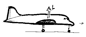
Simplistically, an "old-fashioned" airplane has an asymmetric wing profile (at take-off even more so because of the flaps). Such a profile will start producing lift as soon as you start moving, and if you had enough take-off space, the aircraft would fly off the ground even without rotating it - in practice you rotate to get a more optimum angle of attack, more lift and a better climb speed to "get over the fence".
The Concorde wing, in the same circumstances, is little better than a big flat plank, and will not produce any lift at all, or at least far too little to carry the aircraft.
As M2dude already said, raising the elevons produces enough of a downforce at the trailing edge to lift the nose, and from there on the wing does start producing lift.
Not quite conventional lift, but "vortex lift" (a different subject), but lift just the same.
CJ
I think M2dude has already answered your question.
Anyway, herewith a few very crude scribbles to further illustrate your question and his answers.
Simplistically, an "old-fashioned" airplane has an asymmetric wing profile (at take-off even more so because of the flaps). Such a profile will start producing lift as soon as you start moving, and if you had enough take-off space, the aircraft would fly off the ground even without rotating it - in practice you rotate to get a more optimum angle of attack, more lift and a better climb speed to "get over the fence".
The Concorde wing, in the same circumstances, is little better than a big flat plank, and will not produce any lift at all, or at least far too little to carry the aircraft.
As M2dude already said, raising the elevons produces enough of a downforce at the trailing edge to lift the nose, and from there on the wing does start producing lift.
Not quite conventional lift, but "vortex lift" (a different subject), but lift just the same.
CJ
Last edited by ChristiaanJ; 8th Sep 2010 at 21:42 . Reason: Resizing a picture, typos
8th Sep 2010, 22:47
permalink Post: 284
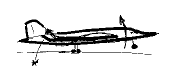
And just to round this off.......you will see from the above that the final insult to a Concorde tyre comes at rotate when (owing to the download caused by the up-elevon input) the download on it is actually
increased
until the rotation passes 7 degrees or so, and vortex lift starts properly.
19th Sep 2010, 16:39
permalink Post: 394
Vortex Lift
There have been a couple of references in this fascinating thread to vortex lift.
I'm sure we've all seen videos of Concorde arrivals and departures where you can see those huge 'wing tip' vortices. It's pretty obvious that at supersonic speeds the airflow must be very different.
Was there some particular airspeed where the airflow pattern changed markedly?
If you decelerated through that speed in level flight did you get a sensation of a sudden increase in drag or need to increase attitude significantly?
19th Sep 2010, 18:10
permalink Post: 396
Is there an aerodynamicist in the house?
Jo90 ,
I'm no expert, so I cannot answer fully.
On a conventional wing, with a conventional profile, at subsonic speed, everything is done to keep the airflow 'attached' to the wing as long as possible, and for as high an angle of attack as possible.
Such a wing stalls because above a certain angle of attack the airflow 'breaks away' from the upper surface of the wing, leading to a sudden loss of lift.
On a very thin slender delta, the airflow already is made to detach right at the leading edge, even at low angles of attack.

Rather than "ruining" the airflow, hence the lift over the entire wing, the result is a vortex that rolls up and re-attaches the airflow to the wing.

At high subsonic speeds, hence low angles of attack, the vortex is located just behind the leading edge, and the rest of the wing produces "conventional" lift.
With lower speeds, hence higher angles of attack, the vortex grows , and ends up covering most of the wing during take-off and landing, as one sees in some photos.
So there is no real sudden transistion from "conventional" to vortex lift.
At no time does the vortex 'break away', so there is no stall in the conventional sense. However, drag increases rapidly, and controllability doesn't improve either, so there are still angle-of-attack limits, even on Concorde.
At supersonic speeds, the entire flow is totally different, and totally unlike the vortex flow.
My own question to an aerodynamicist would be :
Looking at the subtle camber of the leading edge, is there any vortex lift at all during subsonic cruise (Mach 0.95+) or is there a fully attached airflow at that speed / angle of attack to obtain the best possible subsonic cruise?
And if so, when does the breakaway first start?
CJ
Jo90 ,
I'm no expert, so I cannot answer fully.
On a conventional wing, with a conventional profile, at subsonic speed, everything is done to keep the airflow 'attached' to the wing as long as possible, and for as high an angle of attack as possible.
Such a wing stalls because above a certain angle of attack the airflow 'breaks away' from the upper surface of the wing, leading to a sudden loss of lift.
On a very thin slender delta, the airflow already is made to detach right at the leading edge, even at low angles of attack.
Rather than "ruining" the airflow, hence the lift over the entire wing, the result is a vortex that rolls up and re-attaches the airflow to the wing.
At high subsonic speeds, hence low angles of attack, the vortex is located just behind the leading edge, and the rest of the wing produces "conventional" lift.
With lower speeds, hence higher angles of attack, the vortex grows , and ends up covering most of the wing during take-off and landing, as one sees in some photos.
So there is no real sudden transistion from "conventional" to vortex lift.
At no time does the vortex 'break away', so there is no stall in the conventional sense. However, drag increases rapidly, and controllability doesn't improve either, so there are still angle-of-attack limits, even on Concorde.
At supersonic speeds, the entire flow is totally different, and totally unlike the vortex flow.
My own question to an aerodynamicist would be :
Looking at the subtle camber of the leading edge, is there any vortex lift at all during subsonic cruise (Mach 0.95+) or is there a fully attached airflow at that speed / angle of attack to obtain the best possible subsonic cruise?
And if so, when does the breakaway first start?
CJ
19th Sep 2010, 18:27
permalink Post: 398
Anecdotal rther than aerodynamic evidence here - but there was a noticable buffet as one decelerated, accompanied by a significant step in thrust requirement. That point was where we (flight crew) decided we were in vortex lift.
Typical speeds would be 270-280 kts at TO mass and about 230-250kts at landing mass.
I'm not naive enough to believe that it was a 'switch' in aerodynamic modes, but the outcome felt like one.
I'd be slightly surprised if there was much of a vortex at M0.95 since the alpha was fairly low here and I would expect there to be plenty of shockwave activity on the upper surfaces which would suggest that a standing vortex would be likely to be badly disrupted.
Anyone know some definite answers?
19th Sep 2010, 18:53
permalink Post: 401
Quote:
|
Originally Posted by
Bellerophon
I'm not aware of what Haynes may say about Concorde - I don't have a copy of the book and haven't read it - however it is well documented that landings at weights up to 130,000 kgs were permitted on Concorde, provided various conditions were met.
It was a Conditional Procedure called Fuel Saving Landing . BA did not plan flights to land at 130,000 kgs but the procedure was available for use when required. In practice it was rarely used, and the occasions on which it was used tended to be following a return to the departure airfield, or a diversion in the early part of the flight, with the aircraft still above the (normal) maximum landing weight, in order to reduce the amount of fuel to be jettisoned. |

By the way, I highly recommend this book to everybody, a different point of view, new photos and nice info regarding this bird.
Quote:
|
Originally Posted by
M2Dude
Hi again. Yes, the Ronivaniemi charters were supersonic) and VERY popular).
|
Nice info regarding BA004! But if a repair was needed, would BA004 take-off anyway to Gatwick or Birmingham? Has it ever arrived a bit late?
Quote:
|
Originally Posted by
ChristiaanJ
My own question to an aerodynamicist would be :
Looking at the subtle camber of the leading edge, is there any vortex lift at all during subsonic cruise (Mach 0.95+) or is there a fully attached airflow at that speed / angle of attack to obtain the best possible subsonic cruise? And if so, when does the breakaway first start? |
Quote:
|
Originally Posted by
Jo90
Was there some particular airspeed where the airflow pattern changed markedly?
|
Thank you all, awesome topic!!

19th Sep 2010, 20:06
permalink Post: 404
Quote:
|
Originally Posted by
EXWOK

Anecdotal rther than aerodynamic evidence here - but there was a noticable buffet as one decelerated, accompanied by a significant step in thrust requirement. That point was where we (flight crew) decided we were in vortex lift.Typical speeds would be 270-280 kts at TO mass and about 230-250kts at landing mass.
|
For some reason, those figures sound familiar even to me.... (from some other discussion, probably).
It would definitely put optimum subsonic cruise at about 350 kts in the "conventional lift" zone.
Quote:
| Anyone know some definite answers? |
CJ
20th Sep 2010, 16:18
permalink Post: 424
Interesting & nostalgic thread. Nice to see this monumental aviation achievement still generates such passion...
In case it's of interest (and suitable health warning as the memory fades)...
The heat did evaporate water vapour in the airframe - reducing corrosion. I remember when the 5 BA aircraft were returned to service, after the post-accident mods, their weight and balance certificates were prepared and found to be out by (IIRC) more than a tonne. This represented water in the airframe present after a year on the ground, and was gone again after a couple hours of supercruise on return to service. Back to the weighbridge for new W&B Certificates....
Vortex lift caused buffet which felt very similar to a conventional wing's stall/low speed buffet. At landing weights (I hate the trend of using the term "mass": weight is a force, mass is not!) you felt the buffet start as you reduced speed (CAS: Vc) to about 250kts. It was handy as a reminder that you should select visor down / nose to five below 250kts (the recommendation was as you slowed through 270kts, but latterly we were in the habit of holding at 250kts nose/visor up - I think TCAS was quoted as a backup to the more limited visibility in that config). At takeoff weights, the buffet went at more like 270kts accelerating. So I'm pretty sure there was no vortex lift at AoA > 7 degrees (250kts at LW).
Recommended subsonic cruise at MTOW was F260 / M0.95 which was equal to Vmo of 400kts (CAS). It was best cruise because Vc=400kts was also min drag at MTOW. F280 meant a slightly more draggy speed of 384kts, but some preferred it because when cleared to climb & accelerate supersonic (the official expression was "go for it") it gave you a bit of slack against Vmo when eng put the reheats in. But we tended to ignore the overspeed warning anyway: it was supposed to go really really fast...
We never flew with visor down and nose up unless it was bust - that config was only used during pushback (except one captain who always thought it looked better visor up....). Visor down max Vc was 325kts/M0.8 so it would limit subsonic cruise, and besides it made a racket like that.
It was a beaut in x-winds - a total lack of yaw-roll couple meant you just straightened the 'plane up with rudder and carried on into the flare as normal. No roll to counteract, and the sideways "lift" created by the rudder deflection on the fin pretty much equalled the x-wind drift. Nice.
Wind limits were Crosswind 30kts (15kts contaminated or autoland), Headwind for autoland 25kts (or manual "reduced noise" approach: that's a technical way we used to reduce the noise footprint down to 800' by flying at 190kts then reducing to a target speed of Vref+7kts at that point). Tailwind 10kts. All these limits were, of course, subject to "on the day" performance limits calculated at the time. I seem to remember there was an over-arching limit of 6000' on r/w length, subject again to "on the day" performance limits. OK, I cheated on this paragraph and dug out FM Vol 2a.
There were loads of other limitations which were, by and large, more "esoteric" than a conventional airliner and which had to be learned for the conversion course. It really made the head hurt, and would have been impossible without a big loverrly picture of the beast on the wall chucking out yellow smoke and making noise. Even a static picture of her seemed to make noise...
No one who flew it could really believe their luck, but one thing for sure is "they don't build them like that any more"...
Ahhhhhhhhhhhhhh..........
21st Sep 2010, 15:39
permalink Post: 442
Quote:
|
Originally Posted by
Nick Thomas
I just wondered if there was any side slip problems etc due to the air flow being blocked to the vertical tail by the big delta wing especially at large AoA on landing? If so what was the undoubtably clever solution?
|
Your questions were already partly answered by NW1.
The solution was indeed in those two narrow strakes on the nose that generated a vortex on either side, the higher the AoA, the stronger.
Those two vortices "folded upwards", well before the leading edge of the wing, and around to the top of the fuselage, where they "stuck down" the air flow right to the end.
Hence the vertical tail was not "blanketed" by disturbed/turbulent air from the fuselage, and remained effective even at quite high angles of attack.
It was certainly a clever solution... but not new.
As stilton said, it was already used on the MD80.
On Concorde they had already been tested in the windtunnel and found to be effective, so if you look at photos of prototype 001 on its very first flight you will see they're already in place.
Vortices are funny things... usually you don't see them, but they contain quite a lot of energy and persist for quite a long time before dissipating. That's why those two small planks on Concorde work so well.
CJ
23rd Sep 2010, 02:10
permalink Post: 450
That's why those two small planks on Concorde work so well.
Quite a common trick of the trade eg with fighters eg the leading edge extension (LEX - the narrow aspect delta at the front of the wing) on the F18 and others. There are plenty of pix around with the vortex made visual due humidity and it can be seen to be tight, curly and designed nicely to interact with the fins - which, for the F18 has caused much in the way of fatigue related grey hairs in the boffin fraternity.
and especially it's used in moving the CofG.
again, a common observation eg 747-400 tail tanks .. just a matter of how much the movement is required to be.
18th Nov 2010, 00:32
permalink Post: 719
Mr Vortex
First of all, 'welcome aboard'; I'll do my best to answer your queries.
The area of the primary nozzle Aj, was varied for 2 'primary' purposes :
:
a) To act as a military type 'reheat' or 'afterburning' nozzle; opening up to control the rise in jet pipe pressure P7, as reheat is in operated.
b) To match the INLET TOTAL TEMPERATURE RELATED (T1) speed of the LP compressor N1 to the HP compressor N2 against a series of schedules, ensuring easch spool is as close as safely possible to its respective surge boundary, (with a constant TET, see below) and therefore at peak efficiency.
Now, in doing this a complex set of variables were in place. As the nozzle is opened there is a REDUCED pressure and temperature drop across the LP turbine. This has the effect of enabling a HIGHER N1,as less work is being done by the turbine. Also the change (in this case a decrease) in the temperature drop across the turbine will obviously affect the turbine entry temperature, TET. A closing down of the nozzle would obviously have the opposite effect, with a DECREASE in N1 and an INCREASE in TET.
In practice at a given T1 there was always an ideal N1 versus N2 on the control schedule (known as the E Schedule), the TET staying more or less constant from TAKE-OFF to SUPERSONIC CRUISE!!
As far as noise abatement went; when reheat was cancelled and power reduced after take-off, an E Schedule known as E Flyover was automatically invoked. This had the effect of driving the primary nozzle nearly wide open, reducing both the velocity of the jet efflux and in essence the noise below the aircraft.
The real beauty of this primary nozzle system was that it really did not care if the engine was operating dry or with afterburning ('it' did not even know). P7 was controlled against a varying compressor outlet pressure, the variable being controlled by a needle valve operated by the electronic engine controller. (If this is unclear I can post a diagram here that shows this control in action).
As soon as I receive back the majority of my technical notes that I have out on long-term loan (I've requested their return) I will post a schematic here. But for now; The tanks were vented to atmosphere via tandem vent galleries, the two vents openings being on the left hand side of the tail-cone. At an absolute static pressure of 2.2 PSIA (around 44,000') twin electrically operated vent valves, also in the tail-cone, would automatically close; the tanks now being pressurised via a small NACA duct on the right side of the fin. A tank pressure of around 1.5 PSIG was maintained by the action of a small pneumatic valve at the rear of the aircraft. There was massive protection built in to guard against over-pressure (eg. if a tank over-filled in cruise).
I hope this answers some of your queries
Best Regards
Dude
Quote:
|
1. I've heard that Concorde use the primary nozzle to modulate the noise and the speed of the N1 compressor. How does it work? and does it help to reduce the noise a lot?
2.Another thing about Primary nozzle. If i recall it correctly, the primary nozzle can also use to control the Inlet Turbine temperature. Is that true? How is that work |
The area of the primary nozzle Aj, was varied for 2 'primary' purposes
:
a) To act as a military type 'reheat' or 'afterburning' nozzle; opening up to control the rise in jet pipe pressure P7, as reheat is in operated.
b) To match the INLET TOTAL TEMPERATURE RELATED (T1) speed of the LP compressor N1 to the HP compressor N2 against a series of schedules, ensuring easch spool is as close as safely possible to its respective surge boundary, (with a constant TET, see below) and therefore at peak efficiency.
Now, in doing this a complex set of variables were in place. As the nozzle is opened there is a REDUCED pressure and temperature drop across the LP turbine. This has the effect of enabling a HIGHER N1,as less work is being done by the turbine. Also the change (in this case a decrease) in the temperature drop across the turbine will obviously affect the turbine entry temperature, TET. A closing down of the nozzle would obviously have the opposite effect, with a DECREASE in N1 and an INCREASE in TET.
In practice at a given T1 there was always an ideal N1 versus N2 on the control schedule (known as the E Schedule), the TET staying more or less constant from TAKE-OFF to SUPERSONIC CRUISE!!
As far as noise abatement went; when reheat was cancelled and power reduced after take-off, an E Schedule known as E Flyover was automatically invoked. This had the effect of driving the primary nozzle nearly wide open, reducing both the velocity of the jet efflux and in essence the noise below the aircraft.
The real beauty of this primary nozzle system was that it really did not care if the engine was operating dry or with afterburning ('it' did not even know). P7 was controlled against a varying compressor outlet pressure, the variable being controlled by a needle valve operated by the electronic engine controller. (If this is unclear I can post a diagram here that shows this control in action).
Quote:
3.Finally, does some one have a schematic or the fuel vent system?

|
I hope this answers some of your queries
Best Regards
Dude
18th Nov 2010, 03:13
permalink Post: 721
Hi M2 Dude
Thanks very very much for your long reply and good explanation.
- So once we select the Engine schedule to mode Hi or F/O the Prim nozzle will
open wider causing the pressure at the Prim nozzle to drop and hence the
higher flow of the exhaust through the LP turbine = Higher N1 RPM.
Am I understand it correctly?
- According to your reply, the E schedule that will provide the most thrust is
the Low mode since the prim nozzle area will be the smallest among all of the
other mode which mean the highest pressure and temperature.
Am I understand it correctly? And if so why do BA [as far as I know] told the FE
to use Hi mode? Because the higher thrust can be obtain with higher N1?
- Also does the the Hi mode can deliver the higher N1 RPM, does that mean
the Engine control unit must deliver the higher fuelflow rate in order to keep
N2 run at the constant speed [higher N1 speed => higher pressure => more resistance
=> higher Fuelflow require to keep N2 run at constant speed]
Thanks for all of your reply!
Best Regards
Vortex
18th Nov 2010, 12:25
permalink Post: 724
Mr Vortex
More or less you are correct yes, but remember that schedule selection was more or less automatic. (
E Flyover
was armed prior to take-off, and
E-MID
during approach by the E/O, otherwise it was more or less a 'hands off' afair).
Oooo no, we are way adrift here I'm afraid. I'm trying not to get too 'heavy' with this explanation, and I've enclosed below the Rolls-Royce E Shedule diagram to try and help clarify everything. (I've edited out the exact equation figures in deference to Rolls-Royce). Where N1/√θ and N2/√θ is quoted, the term '
θ
' related to
T1 in degrees K/288
. (288 deg's K being 15 deg's C). The hotter things are the higher the spool speed scheduled is, and visa-versa for lower temperatures. Only at a T1 of 15 deg's. C (Standard day temperature) does N/√θ equate to N. (But remamber that T1 is TOTAL temperature, that varies with Mach Number).
The use of E LOW above 220KIAS was not only strictly inhibited by the automatics, if you over-rode the automatics and 'hard selected' E LOW , the aircraft would fall out of the sky when reheat was cancelled at Mach 1.7. This was because the low N1/√θ scheduled by E LOW would now invoke an N2/√θ limit (The E3 Limiter in the diagram) and claw off fuel flow by the tonne.
The most efficient schedule for supersonic cruise was E HI which again would be automatically selected.
E-MID was automatically selected during afterburning operation, to minimise the chance of an N1 overspeed on cancellation of reheat. E-MID could also be selected by the E/O for noise abatement approach.
E Flyover was as we discussed before used for take-off flyover noise abatement as well as subsonic cruise if desired. (If Mach 1 was exceeded with E Flyover still selected, a yellow NOZZLE light illuminated and E HI would be automatically selected.
I sincerely hope that this blurb is not clear as mud, feel free to ask away.
Nope, that is the beauty of it all. Because of the part choking of the LP turbine section of the engine, the pressure changes due to Aj variation were felt exclusively by N1 and not N2. (Clever, these Rolls-Royce guys
 ).
).
Regards
Dude

Quote:
| - So once we select the Engine schedule to mode Hi or F/O the Prim nozzle will open wider causing the pressure at the Prim nozzle to drop and hence the higher flow of the exhaust through the LP turbine = Higher N1 RPM. Am I understand it correctly? |
Quote:
| According to your reply, the E schedule that will provide the most thrust is the Low mode since the prim nozzle area will be the smallest among all of the other mode which mean the highest pressure and temperature. Am I understand it correctly? And if so why do BA [as far as I know] told the FE to use Hi mode? Because the higher thrust can be obtain with higher N1? |
The use of E LOW above 220KIAS was not only strictly inhibited by the automatics, if you over-rode the automatics and 'hard selected' E LOW , the aircraft would fall out of the sky when reheat was cancelled at Mach 1.7. This was because the low N1/√θ scheduled by E LOW would now invoke an N2/√θ limit (The E3 Limiter in the diagram) and claw off fuel flow by the tonne.
The most efficient schedule for supersonic cruise was E HI which again would be automatically selected.
E-MID was automatically selected during afterburning operation, to minimise the chance of an N1 overspeed on cancellation of reheat. E-MID could also be selected by the E/O for noise abatement approach.
E Flyover was as we discussed before used for take-off flyover noise abatement as well as subsonic cruise if desired. (If Mach 1 was exceeded with E Flyover still selected, a yellow NOZZLE light illuminated and E HI would be automatically selected.
I sincerely hope that this blurb is not clear as mud, feel free to ask away.
Quote:
|
- Also does the the Hi mode can deliver the higher N1 RPM, does that mean the Engine control unit must deliver the higher fuelflow rate in order to keep N2 run at the constant speed [higher N1 speed => higher pressure => more resistance
=> higher Fuelflow require to keep N2 run at constant speed] |
).
Regards
Dude
Last edited by M2dude; 18th Nov 2010 at 15:04 . Reason: I goofed.. (another sign of age)
19th Nov 2010, 15:00
permalink Post: 738
Thanks a lot M2Dude
So if we select E Low at M>1.7 the N2 will ovespeed and hence higher fuelflow. Am I understand it right? Also, what E mode provide the
best config shape [lest sat suitable] that provide a con-di nozzle for
maximize thrust. [Not open to wide that exhaust can't reach M1 at the
throat of Prim nozzle].
And another quesrion here, the engine control unit use which parameter to control the thrsut. The EGT, or N2, or P7.
Thanks for yours reply.
Best Regards
Vortex
PS. thanks for your nice graph and fuel vent schematics too.
19th Nov 2010, 22:00
permalink Post: 742
Mr Vortex
Not quite; remember that the N1s and N2s in the E SCHEDULE graph are non-dimentional. ie. they vary with temperature. As the temperature rises (with increasing Mach Number) the scheduled spool speeds increase. What really happens (I did not explain it correctly first time) is that the much lower N1 demanded by the use of E LOW at high speed results in a much further closed primary nozzle than normal, pushing up TET (and EGT) and we run hard into the EGT limiter, which claws fuel flow off, to the extent that the ramps and spill doors come down to their preset limits, almost as if there is a flame-out. The net result is a huge reduction in thrust. The condi was formed as the primary nozzle naturally took up a near fully open position in supersonic cruise and the wide open secondary nozzle buckets completed the picture. The schedule used here was E HIGH. I've noticed a couple of errors on the graph, the main one being that E HIGH is used with reheat off but with Vc
>
220 KIAS
Apart from being set as a variable limit, EGT normally played no role in the control loops (there were 2 loops, the 'governor' and 'positioner' loops). P7 played no part whatsoever in any case, the main variables were; N2, throttle valve position, throttle transmitter position, T1, total pressure and static temperature..
Feathers McGraw
Oh nooooo... I've been outed
Best regards
Dude
Quote:
|
So if we select E Low at M>1.7 the N2 will ovespeed and hence higher fuelflow. Am I understand it right? Also, what E mode provide the
best config shape [lest sat suitable] that provide a con-di nozzle for maximize thrust. [Not open to wide that exhaust can't reach M1 at the throat of Prim nozzle]. |
Quote:
| And another quesrion here, the engine control unit use which parameter to control the thrsut. The EGT, or N2, or P7. |
Feathers McGraw
Quote:
| If you watch some of the more recent Concorde programmes, such as "Concorde's Last Flight", you'll hear and see the reaction of the various people (including our very own Dude) from the BA side of things as they talk about their charge. |
Best regards
Dude
Last edited by M2dude; 20th Nov 2010 at 05:10 .
21st Nov 2010, 05:58
permalink Post: 749
Thanks very much M2Dude for your answer.
I'm wonder if all 4 Olympus 593 all died in flight and unable to restart. Is it
possible to be able to land at the nearest airport?
I've heard some of the double delta fighter like saab 35 Draken suggested that
if engine was died inflight, ejection was recommend since it isn't possible to land
[maybe due to the enormous of drag create while aircraft approaching the
runway]. So if i'm wrong please correct me. I'm no expert in saab draken.
Thanks for all of yours reply.
Best regards
Vortex
21st Nov 2010, 15:37
permalink Post: 751
Mr Vortex
An ejection was recommended because it was possible, not that was necessarily impossible to land a Draken dead stick. F-16s have done a number of them, I witnessed one at KTPA. There was a video of the HUD view of one at NAS Glenview, IL.
To your question, it would depend on distance to go to the airport, glide ratio (high but probably not terribly worse than any conventional airliner) and most importantly the capability of the RAT providing hydraulic power.
M2dude , any idea of the min IAS for the RAT to provide the juice and hydraulics? Would it be as low as Vapp minus some margin?
GF
21st Nov 2010, 18:38
permalink Post: 754
Thanks for the very complete answer,
Brit312
. As I gather,
Mr Vortex
is a relative novice (from the profile, I'm making an assumption), an additional point. As supersonic flight was overwater, the loss of all engines above M1.2 pretty much precluded a airport landing except for initial acceleration and final deceleration. And, at that, initial acceleration would require a 180 degree turnaround, probably reducing the time above M1.2. Over sovereign land, you would, I presume, be going directly to the slower than M1.2 drill and the possibility of an airport landing.
GF
GF