21st Nov 2010, 18:48
permalink Post: 755
Quote:
|
Originally Posted by
galaxy flyer

As I gather,
Mr Vortex
is a relative novice (from the profile, I'm making an assumption), an additional point.
|
I'm always amazed about how many people, who've never flown on Concorde, sometimes never even have seen her fly, still try to find as much about her as they can, even on technical issues they'd never bother with about for any aircraft (apart from maybe the SR-71).
It's worth passing on the heritage, I think.
CJ
21st Nov 2010, 20:11
permalink Post: 756
Thanks for all of your reply.

As galaxy flyer said, I'm haven't met real Concorde in my life and neither see her
flying too. So I'm study about her for a while from flight simulator, manual,
some book, and this forum to get to know more about this amazing plane.
So if i'm bother you guys with a non sense question I'm apologize for that.
Best Regards
Vortex
As galaxy flyer said, I'm haven't met real Concorde in my life and neither see her
flying too.
So I'm study about her for a while from flight simulator, manual,
some book, and this forum to get to know more about this amazing plane.
So if i'm bother you guys with a non sense question I'm apologize for that.
Best Regards
Vortex
21st Nov 2010, 21:21
permalink Post: 758
More than that,
ChristaanJ
, there are only stupid mistakes!
Mr Vortex . At your age, I was doing the same thing, asking all sorts of questions that required knowledge and understanding before my years and experience. Keep doing so, it is the only way to expand your mind. And you never know when that obscure fact will come in handy
GF
Mr Vortex . At your age, I was doing the same thing, asking all sorts of questions that required knowledge and understanding before my years and experience. Keep doing so, it is the only way to expand your mind. And you never know when that obscure fact will come in handy
GF
21st Nov 2010, 22:14
permalink Post: 760
Thanks to all of your cheer up reply. I'm really appreciate that.

Best Regards
Vortex
Best Regards
Vortex
24th Nov 2010, 03:12
permalink Post: 763
Hi all,
I've just wonder that does the Concorde use a surge tank or
some a kind of a NACA duct like on B737 for pressurize the fuel in a tank?
Also, in Concorde F/E panel around the fuel control panel there're switch call
trim pipe drain switch. Which I tried to read and figure it out but finally I don't
know what it actually do and in which circumstance do we need to use it.
Thanks for yours reply.
Best Regards
Vortex
I've just wonder that does the Concorde use a surge tank or
some a kind of a NACA duct like on B737 for pressurize the fuel in a tank?
Also, in Concorde F/E panel around the fuel control panel there're switch call
trim pipe drain switch. Which I tried to read and figure it out but finally I don't
know what it actually do
and in which circumstance do we need to use it.
Thanks for yours reply.
Best Regards
Vortex
26th Nov 2010, 08:47
permalink Post: 781
speedbirdconcorde
Yes we did, just a couple if I remember correctly and relatively minor failures at that. (Regular ultrasonic NDT inspections had been instigated to pre-empt these failures from actually occuring). New elevon purchases were rightly seen to be the answer to the problem; the poorly designed trailing edge extension modifications of the late 1970's were as was said before, the source of these failures, due to moisture ingress in the honeycombe structure).
Mr Vortex
As has been posted previously, there was a small NACA duct on the right hand side of the fin, that provided the air source for fuel tank pressurisation. This pressure was controlled to 1.5 PSIG.
This switch operated two valves that would drain out any residual fuel for maintenance (for example, replacing a vent valve); it was not used very often however.
Islander539 and ChristiaanJ
The actions of Airbus at Filton are nothing short of disgusting. By 'removing the insulation' you will need to strip the cabin completely bare (seats, galleys, ceiling panels and all of the side-wall panels). They say that 'Filton was only ever going to be an interim home for Concorde', what total crap
!!
crap
!!
The idea is to 'cocoon' the aircraft 'until a permanent home is found'. I hope all readers here realise that this will involve BREAKING UP THE AIRFRAME to make it road transportable. The reasons that scarebus are giving for all this are vague and misleading, but here's my take. There are pressures around from various people and bodies 'to return a British Concorde to flying condition.' Now a lot (NOT ALL) of these people although very well intentioned are not that well informed and their wishes are not reasonably possible. But the pressures exist nonetheless, and scarebus will do anything to prevent this possibility, nomatter how unlikely, from being progressed. So we have G-BOAF, the youngest Concorde in the world, with the lowest airframe hours, in pretty good structural condition (she's suffered from being outside for 7 years, but nothing terminal) and actually in the hands of the dreaded scarebus (who would rather forget that Concorde ever existed, and was almost certainly the reason why they even noe exist). Doesn't take much working out now, does it?
Dude
Quote:
Regarding the rather important role of the elevons on Concorde
 where there any failures during her time in the skies ?
|
Mr Vortex
Quote:
|
I've just wonder that does the Concorde use a surge tank or
some a kind of a NACA duct like on B737 for pressurize the fuel in a tank? |
Quote:
Also, in Concorde F/E panel around the fuel control panel there're switch call trim pipe drain switch. Which I tried to read and figure it out but finally I don't know what it actually do
 and in which circumstance do we need to use it
|
Islander539 and ChristiaanJ
The actions of Airbus at Filton are nothing short of disgusting. By 'removing the insulation' you will need to strip the cabin completely bare (seats, galleys, ceiling panels and all of the side-wall panels). They say that 'Filton was only ever going to be an interim home for Concorde', what total
crap
!!
The idea is to 'cocoon' the aircraft 'until a permanent home is found'. I hope all readers here realise that this will involve BREAKING UP THE AIRFRAME to make it road transportable. The reasons that scarebus are giving for all this are vague and misleading, but here's my take. There are pressures around from various people and bodies 'to return a British Concorde to flying condition.' Now a lot (NOT ALL) of these people although very well intentioned are not that well informed and their wishes are not reasonably possible. But the pressures exist nonetheless, and scarebus will do anything to prevent this possibility, nomatter how unlikely, from being progressed. So we have G-BOAF, the youngest Concorde in the world, with the lowest airframe hours, in pretty good structural condition (she's suffered from being outside for 7 years, but nothing terminal) and actually in the hands of the dreaded scarebus (who would rather forget that Concorde ever existed, and was almost certainly the reason why they even noe exist). Doesn't take much working out now, does it?
Dude
1st Dec 2010, 11:32
permalink Post: 821
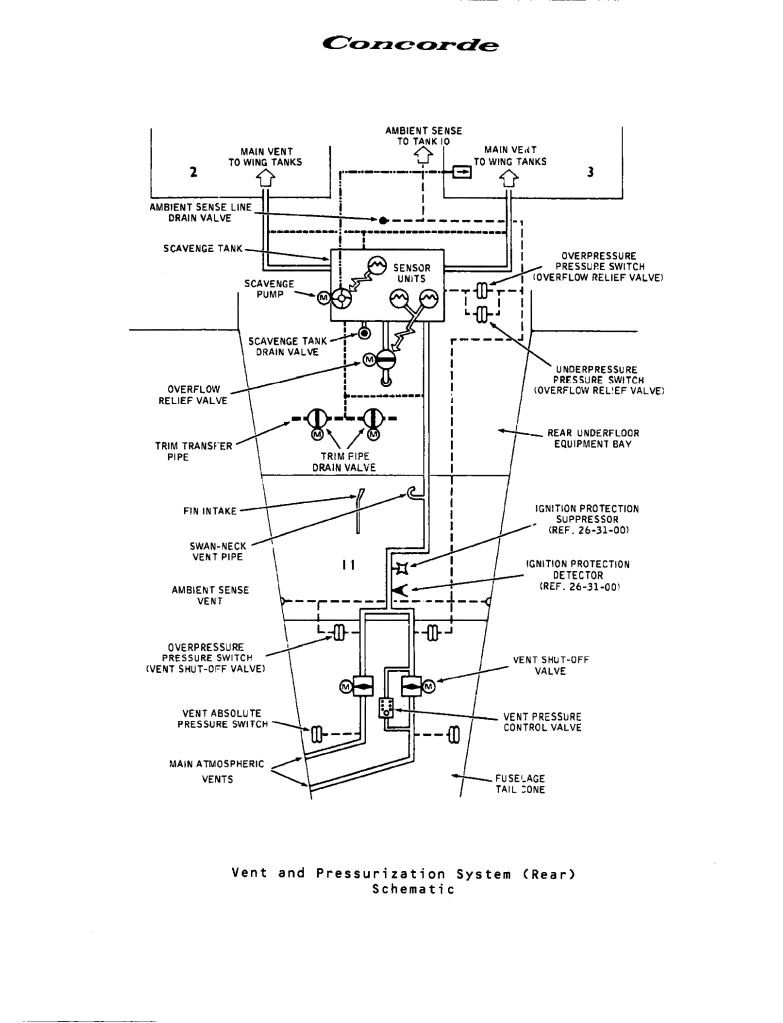
Fuel tank vent and pressurisation
Mr Vortex
Finally as promised, here is a schematic of the AFT part of the fuel vent system. As you can tsee the fin intake pressurises the air space above tank 11, and hence, via the Scavenge Tank air-space, the remaining tanks. (Also you can see the Trim Pipe Drain Vaves you were asking about.
Regards Dude
Quote:
Finally, does some one have a schematic or the fuel vent system?

|
Regards Dude
22nd Dec 2010, 08:29
permalink Post: 938
Quote:
|
Originally Posted by
Mr Vortex
I'm wondering that does the auto-stab function in yaw axis does apply some
rudder when pilot fly the aircraft by his hand to prevent the sideslip or dutchroll or not? Also, does the auto stab does "modify" some pilot input to minimize the effect of the turbulence all the time when airplane encounter the turbulence or only when the AP are in the "TURB" mode? Does it help to reduce the stress on the aircraft like the "load alleviation" on the moder aircraft like A380? And final the final question, how the camber help to reduce the shifting position of the center of pressure on the Concorde and if possible where is it on the wing? |
Then, yes the autostabiliser does provide yaw damping to control the Dutch roll, but there was also (from memory) some roll damping.
No, there is no load alleviation function. Concorde had a very low aspect ratio wing which gives in turn a very low lift curve slope, so the loads coming from hitting gusts are quite modest and load alleviation was not needed. The autostabiliser was working all the time, not just when A/P was engaged. Since the span was also low the manoeuvre bending moment was also small so again load alleviation was not required. BTW, I believe that the A380 load alleviation is just this manoeuvre case not gust loads. The A320 had gust load alleviation on early models, but it proved to be a pain in the neck and was gratefully dropped when the MTOW went up and made manoeuvre loads the critical design case.
Finally, the camber is spread all over the wing. In cross section it looks like a banana with the bent bit like a shallow 'U' and the leading edge drooped downwards, so the whole thing lookss like a distorted 'S'
CliveL
22nd Dec 2010, 12:01
permalink Post: 940
Turb mode
'Dude -
I didn't ever use this mode, and never saw anybody else use it.
Significant turbulence was almost unheard of in supercruise - light to mod was the worst I ever had. Subsonic one would be subject to the same air as the blunties, but in an aircraft which had a high wing loading and good controls. Once you got down into the low-level turbulence on a windy day (say 2000' and below) you were in vortex lift and this seemed even better.
I flew this machine through some vicious conditions and it was - by a country mile - the best aeroplane I've ever flown in bad air, better even than the 747. I could bore you with war stories, but will illustrate the point with the time we asked Tower to advise the aircraft following us that it was pretty wild below 2000', only to hear that everyone else had cleared off owing to the wind conditions.......
The only people that really got a rough ride were the flt crew, who were at the front of a long extension ahead of the really stiff part of the hull, which tended to whip around long before it got bumpy in the cabin.
It wasn't like flying a transport aircraft at all in rough conditions, and this was a real help in keeping a prestige operation in the air when bad wx appeared. (Of course it wouldn't have helped in the present BAA-induced debacle).
22nd Dec 2010, 16:22
permalink Post: 944
Thanks for yours reply.
BTW, what about the super-stabilization? Does it only function when the
aircraft was lift on for 10 minute or for a whole flight regime? Also, what is
the stalling AoA of the Concorde?
Finally, What does the function of the Thrust recuperator and how does it work?
Edit: According to the CliveL picture, why Concorde wing LE has to droop down?
Is it use to produce the "negative drag" by the vortex?
Also, does the tip of the wing always has a negative AoA at all flight regime
or does it gonna bend up as the airspeed increase?
Thanks for all of yours reply.
Best regards
Last edited by Mr.Vortex; 22nd Dec 2010 at 16:31 . Reason: add something
22nd Dec 2010, 17:32
permalink Post: 946
NW1
- amen..........
Clive L - the whole aeroflexing of the 'A' tanks thing was something mentioned during ground school on my conversion course; I may have misunderstood or it may have been less than accurate info.
Mr Vortex - the superstab was always available, though clearly it wasn't a regime one could get into during many phases of flight. As for the 'stalling' alpha - it doesn't have any meaning on a delta. By normal standards Concorde lifted off and landed in what would be called a 'stalled' condition on a conventional aircraft; in Concorde this was 'vortex lift' and was the secret to having an 1100kt speed range on one wing section. (We've talked about this much earlier in the thread).
The limiting factors for max alpha are pitch-down control and drag. IIRC the ability to stop pitching up ended at about 21-22degs alpha (CliveL will know exact numbers I guess!).
Stick shake went off at 16.5degs and stick 'nudger' (badly named - nearly tore my arms out when we tried it on the conversion course) at 19.5 degs, although this could go off sooner under phase advance if the rate of increase was high. (NB - all the above from memory; flt crew with manuals or development men with proper knowledge feel free to correct)
Lastly - the thrust recuperator was explained by M2dude much earlier in the thread, I'll have a look for it. Short answer - clever gizmo on the port(?) fwd outflow valve to recover thrust from outflow air.
22nd Dec 2010, 20:13
permalink Post: 950
Quote:
|
Originally Posted by
exwok
Hazy recollection - effectively an additional autostabilisation input in the nosedown sense active at high alpha/low EAS.
Ultimately applied a further nose down elevon input (4 degrees????) if EAS was less than (140kts???? That's a VERY low speed). (Colloquially known as 'super-duper stab' on my course) |
To cover this case the 'superautostabiliser'was developed. It effectively restricts the rate of variation of incidence so that, if the pilot entered into an avoidance manoeuvre of sufficient magnitude to trigger the stick wobbler, i.e. about 1.5g, he would be able to recover easily without exceeding the maximum incidence demonstrated in flight (which was in fact slightly greater than the maximum steady incidence limit). This superautostab had gain scheduled against AoA and also included phase advanced pitch rate and speed terms. Finally, there was a 'yaw superautostabiliser which applied rudder as a function of lateral acceleration to restrict sideslip which (see below) could affect the maximum lift attainable. [Note that because of the dynamics of slender aircraft operating at high AoA it was readily possible to develop sideslip in a turn]
Hope that is clear.
Whilst talking about maximum lift etc. can I confirm the numbers quoted in an earlier posting for the start of vortex lift - about 6 or 7 deg AoA at low speed, and for the AoA at maximum lift - about 23 deg. This is where the pitching momemt curve vs AoA 'breaks'. It is not a stall in the conventional sense because of course the flow over the leading edge has been separated long ago. Instead it is the AoA at which the LE vortices become 'too big for their boots' and go unstable and 'burst'. This AoA is sensitive to sideslip and the leading wing half will go first.
CliveL
23rd Dec 2010, 09:21
permalink Post: 963
Mr Vortex
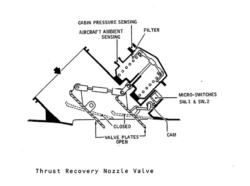
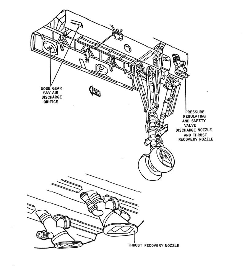
The Thrust recuperator (or thrust recovery nozzle) was fitted to the outlet of #1 (that is, left hand) forward discharge valve (outflow valve in Boeing speak) only. It was a variable 'louvre' type nozzle that would progressively close between 3 and 7.5 PSI diff'. The idea was to direct pressurisation outflow air directly backwards along (theoretically) the aircraft centre line (That at least was the theory). I read somewhere that at max diff' (10.7 PSIG) it would recuperate some 600 lb of thrust. HOWEVER, this system was fitted to the #1 system only (1 & 2 were used on alternate flights) and there was no performance penalty when the thing was not working. Here are a couple of diagrams.
Best Regards
Dude
Quote:
| , What does the function of the Thrust recuperator and how does it work? |
Best Regards
Dude
Last edited by M2dude; 23rd Dec 2010 at 10:42 . Reason: I stil kant sprell
24th Dec 2010, 13:02
permalink Post: 988
 Christian asked if there was an aerodynamicist in the house - I guess that would be me!
The original question was whether there was any vortex activity in subsonic cruise, but the discussion went on to ask about designing for subsonic drag I think.
The answer to the first bit is that the vortex flow started in a gentle manner from about 6 or 7 deg AoA and got steadily stronger. Depending on the chosen cruise speed and the aircraft weight, the subsonic cruise AoA would have been in the region of 4.5 to 5 degrees, i.e. below any significant vortex development. 6/7 deg would correspond to something in the range 250 to 280 kts probably (I haven't done the sums)
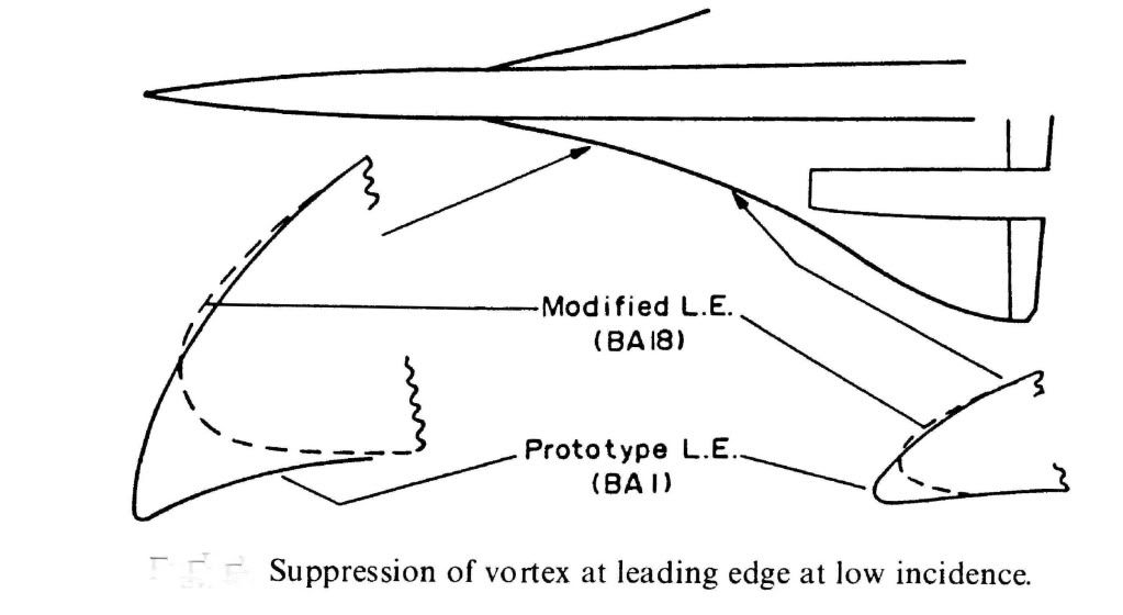
What we were trying to do for subsonic cruise was to have what is known in the trade as 'leading edge suction' acting on a nice bit of forward facing area so that it tried to drag the aircraft forwards as it were. As you can see from the diagram the prototype aircraft had a much more cambered LE so that both suction and forward facing area were very reasonable. This prototype shape was nicely rounded so that LE separation and top surface vortex generation started at a higher AoA than on the production aircraft. Unfortunately this shape, which featured a rather sharp LE on the undersurface, generated a vortex on the undersurface of the wing in supersonic flight and low AoA (near zero 'g'). This vortex got into the intake and caused the engine to surge, so we had to redesign the LE ahead of the intakes as shown. This cost us a little subsonic drag, so you can see from the diagram what you need to do to keep subsonic cruise drag down.
Hope this answers the questions
CliveL
24th Dec 2010, 16:15
permalink Post: 991
Thanks again for a great pics and great explanation.
I'm was wondering that, according to the manual and some document said
that the vortex lift start to form on wing tip first. Why's that happened?
Why not the root of the wing first?
Is it cause by the local wing tip vortex push the air causing more upwash
and hence more effective AoA causing it to reach the stall AoA first is that right?
Also, does the wing vortex on the Concorde has an influence or the effect on
the rudder?
Thanks for your reply.
Best regards
24th Dec 2010, 17:56
permalink Post: 997
[xxxxquote=Mike Bracknell]
Trust me, i'm definitely just here for the ride (so to speak) and quickly defer to you and the others who definitely know! Mike Bracknell[xxxx/quote]
Hell Mike, I meant I should leave it for others who definitely know, not you!
[xxxxquote]A little p.s. from me - having looked at Clive's diagram on this page showing the bathtubs, aren't the strengtheners the oval cups outboard of the main fixings on the page? with one pointed to by the words "Bottom machined skin panel"?
This looks like it's another layer of shear in order to fulfil the brief of working around the reported skin problems in that area. Just strange it had to break the surface like that? [xxxx/quote]
I don't think so Mike, there are far too many of them. It looks more like 'pocketing' of the machined skin to reduce weight; and incidentally that SA overdid it, since there were clearly cracks developing along the spanwise joints between the various wing sections.
Incidentally, doesn't that picture show ever so clearly why designing and fitting that postGonesse Kevlar liner to the lower skins was such a difficult job!
[xxxxquote=ChristiaanJ]If so, they are indeed shown in the structural repair manual and listed as 'doublers'. There are ten of those, from spar 62 to spar 71.
Reading "between the lines", the modification dates from about 1978, and was applied by successive service bulletins to both the BA and AF aircraft. [xxxx/quote]
Yes, I agree, they look like skin doublers put on as a repair job, and that makes (to me) a lot more sense than additions to increase outer wing stiffness. What has confused me from the beginning was that I equated "outer wing stiffness" with "outer wing torsional stiffness" because I could see why somebody might want to increase that but I couldn't, and can't, see why anyone would want to increase outer wing bending stiffness - if you get a little more dihedral who cares? But additional material to increase or recover fatigue life is another matter altogether.
Why external? Just look at that drawing - where could you add additional bending material easily?
[xxxxquote=Landroger]Digital control is a hell of a lot easier than Analogue - in my humble opinion.[xxxx/quote]
Depends when you were born Roger. Now if you came into this world before WW2 ......
[xxxxquote=Mr Vortex]I'm was wondering that, according to the manual and some document said that the vortex lift start to form on wing tip first. Why's that happened? Why not the root of the wing first?
Is it cause by the local wing tip vortex push the air causing more upwash
and hence more effective AoA causing it to reach the stall AoA first is that right?
Also, does the wing vortex on the Concorde has an influence or the effect on
the rudder? [xxxx/quote]
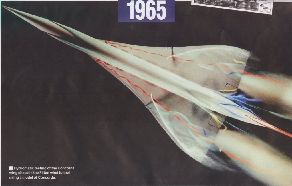
Ah! this gets a little complicated. Every lifting wing generates a pair of vortices at the tip, but these are not the vortices most people associate with Concorde. The massive vortices you see when the air is moist and the water vapour condenses out because of the drop in air pressure inside the vortex start, as you suggest at the wing root from that highly swept leading edge. The wingtip vortices are still there, even when the main vortices are doing their stuff, so Concorde actually has two sets of vortices acting on the upper surface, although this is not obvious to the casual observer.
Simply, the wing vortex has no effect on the rudder.
But whilst I am writing about vortices, can I digress to talk about the 'moustaches' aka GT6. Somebody, I forget who, asked about their use for controlling longitudinal stability and somebody else replied, quite correctly, that they were a contribution to lateral stability. What was happening without them was that high AoA (by which I mean in excess of about 10~12 degrees) the 'crossflow' on the front fuselage generated a pair of small vortices which, in sideslip, wandered across the base of the fin. This gave some sidewash that cancelled the 'incidence' coming from the sideslip itself so that the bottom of the fin was effectively operating at zero slip and therefore zero lift. Result - the weathercock stability dropped to virtually zero for small sideslip angles. The small vortex generators (Generator Turbillon or GT) had the effect of fixing the location of the origin of the forebody vortices so that they didn't wander - in fact they tended to become entrained into the main wing vortices - problem solved.
Now if I can sort it out I will try to upload some pretty pictures showing those two sets of wing vortices.
CliveL
Hell Mike, I meant I should leave it for others who definitely know, not you!
[xxxxquote]A little p.s. from me - having looked at Clive's diagram on this page showing the bathtubs, aren't the strengtheners the oval cups outboard of the main fixings on the page? with one pointed to by the words "Bottom machined skin panel"?
This looks like it's another layer of shear in order to fulfil the brief of working around the reported skin problems in that area. Just strange it had to break the surface like that? [xxxx/quote]
I don't think so Mike, there are far too many of them. It looks more like 'pocketing' of the machined skin to reduce weight; and incidentally that SA overdid it, since there were clearly cracks developing along the spanwise joints between the various wing sections.
Incidentally, doesn't that picture show ever so clearly why designing and fitting that postGonesse Kevlar liner to the lower skins was such a difficult job!
[xxxxquote=ChristiaanJ]If so, they are indeed shown in the structural repair manual and listed as 'doublers'. There are ten of those, from spar 62 to spar 71.
Reading "between the lines", the modification dates from about 1978, and was applied by successive service bulletins to both the BA and AF aircraft. [xxxx/quote]
Yes, I agree, they look like skin doublers put on as a repair job, and that makes (to me) a lot more sense than additions to increase outer wing stiffness. What has confused me from the beginning was that I equated "outer wing stiffness" with "outer wing torsional stiffness" because I could see why somebody might want to increase that but I couldn't, and can't, see why anyone would want to increase outer wing bending stiffness - if you get a little more dihedral who cares? But additional material to increase or recover fatigue life is another matter altogether.
Why external? Just look at that drawing - where could you add additional bending material easily?
[xxxxquote=Landroger]Digital control is a hell of a lot easier than Analogue - in my humble opinion.[xxxx/quote]
Depends when you were born Roger. Now if you came into this world before WW2 ......
[xxxxquote=Mr Vortex]I'm was wondering that, according to the manual and some document said that the vortex lift start to form on wing tip first. Why's that happened? Why not the root of the wing first?
Is it cause by the local wing tip vortex push the air causing more upwash
and hence more effective AoA causing it to reach the stall AoA first is that right?
Also, does the wing vortex on the Concorde has an influence or the effect on
the rudder? [xxxx/quote]
Ah! this gets a little complicated. Every lifting wing generates a pair of vortices at the tip, but these are not the vortices most people associate with Concorde. The massive vortices you see when the air is moist and the water vapour condenses out because of the drop in air pressure inside the vortex start, as you suggest at the wing root from that highly swept leading edge. The wingtip vortices are still there, even when the main vortices are doing their stuff, so Concorde actually has two sets of vortices acting on the upper surface, although this is not obvious to the casual observer.
Simply, the wing vortex has no effect on the rudder.
But whilst I am writing about vortices, can I digress to talk about the 'moustaches' aka GT6. Somebody, I forget who, asked about their use for controlling longitudinal stability and somebody else replied, quite correctly, that they were a contribution to lateral stability. What was happening without them was that high AoA (by which I mean in excess of about 10~12 degrees) the 'crossflow' on the front fuselage generated a pair of small vortices which, in sideslip, wandered across the base of the fin. This gave some sidewash that cancelled the 'incidence' coming from the sideslip itself so that the bottom of the fin was effectively operating at zero slip and therefore zero lift. Result - the weathercock stability dropped to virtually zero for small sideslip angles. The small vortex generators (Generator Turbillon or GT) had the effect of fixing the location of the origin of the forebody vortices so that they didn't wander - in fact they tended to become entrained into the main wing vortices - problem solved.
Now if I can sort it out I will try to upload some pretty pictures showing those two sets of wing vortices.
CliveL
24th Dec 2010, 18:25
permalink Post: 998
 ">
">
Dammit! I thought I had read that [xxxxquote] gave me one of those pretty text boxes ah well, back to the drawing board.....
Unfortunately the only flow visualisation pictures I have are taken at AoAs where the tip vortex has been swallowed by the main vortex, but I thought I would paste them anyway as most people would never have seen them. In this one you can see the forebody vortices quite clearly (the bluegreen streaks) but since it is a zero sideslip case they don't go anywhere near the fin.
On closer inspection, maybe you can just see the wingtip vortices as separate bits of curly white smoke very close to each wingtip.
I'm not going to risk losing all that typing trying to attach a second picture, so I will send that separately
CliveL
24th Dec 2010, 20:04
permalink Post: 1000
What an amazing pictures!!. Thanks CliveL
So does the nose stake of the aircraft that sit below the Capt/FO sliding window
is what you're refer to the GT6 things right?
And if possible,
I would like to know why the vortex start to form on the wing tip
[The outer wing part] first and the moving toward the wing root [inner wing
part] as the AoA increase.
Thanks again
Best regards
24th Dec 2010, 21:16
permalink Post: 1002
Vortex lift.
Okay, for the benefit of all the SLF and Vulgar Curiosity Seekers watching this thread, I will ask the 'nice but dim' question.

I thought I knew a bit about aeroplanes, but M2Dude, CJ and now Clive are pushing my knowledge and understanding to their limits. I see them on Clive's two fabulous images and I've heard some of the pilots - Exwok and Bellerophon - talk of it, but up to now it was something I could take for granted and move on. Now I have to come clean and ask. Vortex lift for dummies please gentlemen?
The end on view is very dramatic and I can only surmise the rotor of air above the wing somehow accelerates it to reduce its density still further, thus generating lift. More lift indeed than the cord profile can provide without creating too much drag. Close? Or wooden spoon for Rog?
Roger.
26th Dec 2010, 09:38
permalink Post: 1009
OK Vortex Lift for Dummies!
Lets start with a comparison of the lft on a conventional subsonic wing with that of a slender wing like Concorde:
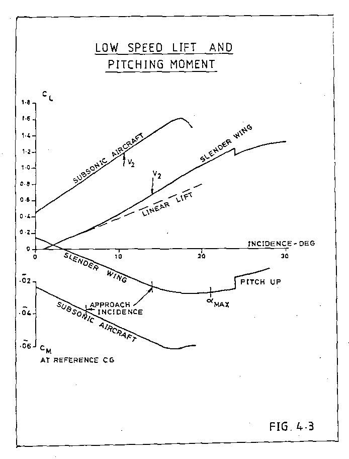
The subsonic line is linear, the slope depends on the geometry of the wing; high aspect ratio wings have a higher slope than low aspect ratio, unswept wings a higher slope than swept. Concorde, being a low aspect ratio swept wing has no chance!
To get a decent approach speed with a delta wing which has 'conventional' wing sections you need either a long U/C and work with high landing AoA or a large wing area to get the wing loading down. I would put the Avro Vulcan in the latter class. A large wing area is bad news for supersonic aircraft, but the Germans, working during WW2 found that if you give the delta sharp leading edges the flow separates at the leading edge and forms a pair of vortices that flow over the upper wing surface.
A vortex, if you could see it, is like a tornado (twister) turned on its side. The essential feature is that it is associated with low static pressures. As you get closer to the centre of the vortex the pressure drops more and more. The red zones at the centre of that transverse view are very low pressure indeed, but even the outer zones have quite low pressure.
I will have to put it up as a separate posting, but there are pictures that show that as AoA increases not only does the vortex get stronger (more suction) but the area of the wing affected by the vortex also inceases. This 'double whammy' gives the vortex a nonlinear effect. This 'nonlinear' lift is what is sometimes called 'vortex lift'.
It doesn't come for nothing - since by definition the flow is separated from the leading edge there is no alleviating 'leading edge suction' to reduce drag, and you won't go very far wrong if you take the drag of an aircraft with such a wing as Profile Drag plus Lift (times) tan AoA.
Concorde is a bit more subtle - the nose of the wing is drooped so that the flow does not separate until the AoA reaches 6 or 7 deg, giving us a good L/D in subsonic cruise whilst still having a healthy lift at approach speed.
Does this fit the bill?
CliveL
Lets start with a comparison of the lft on a conventional subsonic wing with that of a slender wing like Concorde:
The subsonic line is linear, the slope depends on the geometry of the wing; high aspect ratio wings have a higher slope than low aspect ratio, unswept wings a higher slope than swept. Concorde, being a low aspect ratio swept wing has no chance!
To get a decent approach speed with a delta wing which has 'conventional' wing sections you need either a long U/C and work with high landing AoA or a large wing area to get the wing loading down. I would put the Avro Vulcan in the latter class. A large wing area is bad news for supersonic aircraft, but the Germans, working during WW2 found that if you give the delta sharp leading edges the flow separates at the leading edge and forms a pair of vortices that flow over the upper wing surface.
A vortex, if you could see it, is like a tornado (twister) turned on its side. The essential feature is that it is associated with low static pressures. As you get closer to the centre of the vortex the pressure drops more and more. The red zones at the centre of that transverse view are very low pressure indeed, but even the outer zones have quite low pressure.
I will have to put it up as a separate posting, but there are pictures that show that as AoA increases not only does the vortex get stronger (more suction) but the area of the wing affected by the vortex also inceases. This 'double whammy' gives the vortex a nonlinear effect. This 'nonlinear' lift is what is sometimes called 'vortex lift'.
It doesn't come for nothing - since by definition the flow is separated from the leading edge there is no alleviating 'leading edge suction' to reduce drag, and you won't go very far wrong if you take the drag of an aircraft with such a wing as Profile Drag plus Lift (times) tan AoA.
Concorde is a bit more subtle - the nose of the wing is drooped so that the flow does not separate until the AoA reaches 6 or 7 deg, giving us a good L/D in subsonic cruise whilst still having a healthy lift at approach speed.
Does this fit the bill?
CliveL