26th Dec 2010, 09:51
permalink Post: 1010
 Ok, second picture (can anyone tell me how to attach more than one?)
These need a bit of explaining I'm afraid. They are 'oil flow' pictures - you paint the model wing with a mixture of paraffin, engine oil and lamp black and blow air over it. The resulting pattern shows how the air is flowing (or not flowing, which is its primary purpose) over the wing surface.
I the diagram marked up in red the 'S' shaped line is a typical streamline where the air is brought down onto the surface inboard, moves downstream and across towards the tip under the combined action of fore and aft velocity and vortex rotational velocity and tis finally lifted off the surface by the vortex. the triangular zone marked out in red is the area of the wing 'scrubbed' by the vortex flow. If you compare the pictures at various AoA you will see that this area increases substantially as AoA increases.
On the21 deg picture you can also see signs of a second vortex between the main vortex and the wingtip, but this is not the classic 'tip vortex'
CliveL
26th Dec 2010, 12:50
permalink Post: 1012
Vortex Lift
Clive,
Thanks for the diagrams about vortex lift.
I seem to remember, as a flight test engineer having the good fortune to sit in on a fair number of landings during Concorde 'DG development and certification flying, that you could feel the onset of vortex lift from a very light vibration through the airframe, during the slowing down to approach speeds. I think it was more noticeable sitting back at the FTE seats at the instrumentation area in the cabin rather than on the 4th seat on the flight deck. I cannot remember if that was close to the 7 degree onset alpha or something closer to the approach alpha. Has anyone else commented on this?
Andrew
26th Dec 2010, 16:03
permalink Post: 1017
Vortex Lift.
Quote:
|
Does this fit the bill?
CliveL |
As the AoA increases when Concorde slows down, the vortex comes into being and becomes stronger as the angle increases, creating a low pressure tube into which the wing is 'sucked upwards' - vis vortex lift. How did I do?

Quote:
| These need a bit of explaining I'm afraid. They are 'oil flow' pictures - you paint the model wing with a mixture of paraffin, engine oil and lamp black and blow air over it. The resulting pattern shows how the air is flowing (or not flowing, which is its primary purpose) over the wing surface. |

Thanks for the explanation - it was less painful than I had feared.

Roger.
13th Jan 2011, 20:23
permalink Post: 1087
If you look at it from straight ahead it's not really a 'kink'.

From the angle the 'kinky' photo was taken the outer sweep of the ogee wing is towards the camera before sweeping aft to the drooped and washed-out tips and it looks like a kink in the LE sweep. The actual shape is seen better in the picture above. I've spent hours studying our G-BOAC at Manchester and to me the wing is a complex and lovely blend of curves and slopes, with no sudden changes such as a kink would require. Standing under the wing and observing it closely, no kink is apparent.
The wash-out on the tips shows particularly well in the above photo (washout is a forward twist of the wing at the tips to reduce the angle of attack of the tips compared to the rest of the wing, to prevent tip-stalling).
A question I have, relating to the photo above, is about the LE. The LE definately 'droops' in the area ahead of the intakes (it doesn't do so nearer the roots or tips). Is this to provoke a clean flow-breakaway in this area at high angles of attack to encourage the votices to form at this point as the wing transitions to vortex lift?
M2Dude Thanks for the kind words and careful explanations. I take it from your description of the anti-skid that once the mains start to rotate the brakes can be used, as the anti-skid comes 'off' (mains no longer think they are skidding).
I thought there was protection to prevent brake use until the nose wheels have landed, else brake application with the nose high would cause a rapid nose-down pitch, slamming the nosewheels on! Is there any such protection?
Last edited by Shaggy Sheep Driver; 13th Jan 2011 at 21:41 .
14th Jan 2011, 08:29
permalink Post: 1092
Quote:
| A question I have, relating to the photo above, is about the LE. The LE definately 'droops' in the area ahead of the intakes (it doesn't do so nearer the roots or tips). Is this to provoke a clean flow-breakaway in this area at high angles of attack to encourage the votices to form at this point as the wing transitions to vortex lift? |
The prototype had even more 'droop' in front of the intakes, but that produced a vortex at low incidence (near zero 'g') that went down the intakes and provoked surge.
Quote:
| The wash-out on the tips shows particularly well in the above photo (washout is a forward twist of the wing at the tips to reduce the angle of attack of the tips compared to the rest of the wing, to prevent tip-stalling). |
Cheers
Clive
PS: Everyone seems to be adding their favourite Concorde photograph so I thought I would be different and add my LEAST favourite

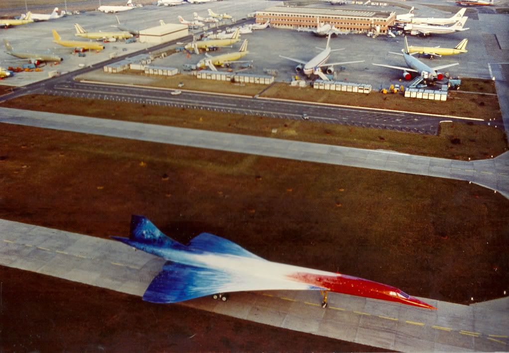 ">
">
Last edited by CliveL; 14th Jan 2011 at 08:43 . Reason: adding a photo and additional remarks
30th Jan 2011, 20:24
permalink Post: 1164
CliveL said
"Sorry SSD, but there ain't no waisting on the fuselage, although the area ruling in that area is quite good. Did you mean where the fuselage starts to taper?"
--------------------------------------------------------
Nope. I meant the waisting of the fuselage where the fin starts. Stand on the steps by the front door where Dude's wife took that picture, and you'll see that the cabin roof is 'waisted in' noticably where the fin is mounted (not the sides of the fuselage which remain parallel - the roof, which is bowed inwards and downwards to reduce the fuselage cross section co-incident with the fin's extension above the fuselage). I see it several times a week on OAC.
You can see it on this picture too, though it's not as obvious as when you look back from the door.

Mr Vortex - Yes, the gradual taper of the nose and of the tail help with area rule. As does the wing leading edge being brought as far forward as possible where it joins the fuselage, so the cross-sectional area increases as gradually as possible, nose to tail, at the wing root.
--------------------------------------------------------
Nope. I meant the waisting of the fuselage where the fin starts. Stand on the steps by the front door where Dude's wife took that picture, and you'll see that the cabin roof is 'waisted in' noticably where the fin is mounted (not the sides of the fuselage which remain parallel - the roof, which is bowed inwards and downwards to reduce the fuselage cross section co-incident with the fin's extension above the fuselage). I see it several times a week on OAC.
You can see it on this picture too, though it's not as obvious as when you look back from the door.
Mr Vortex - Yes, the gradual taper of the nose and of the tail help with area rule. As does the wing leading edge being brought as far forward as possible where it joins the fuselage, so the cross-sectional area increases as gradually as possible, nose to tail, at the wing root.
Last edited by Shaggy Sheep Driver; 31st Jan 2011 at 00:06 .
8th Apr 2011, 07:13
permalink Post: 1280
Jane-DoH
One of the real beauties of the Concorde intake was that it was completely self-startiing, and so unstarts as such were never heard of.
Regarding the vibrations thing, here is my post #80:
I seem to remember that Rolls Royce proposed a solution of their own, whre the right hand pair of engines would rotate ant-clockwise (viewed from the front) rather than the clockwise norm for just about any 'Roller' that I can think of. Although this would have completely solved the vibration problem, and was great business for the folks at RR in Patchway (just about doubling the required number of engines) it was a pretty lousy idea if you were an airline and required a much latger holding of spare engines.
One of the real beauties of the Concorde intake was that it was completely self-startiing, and so unstarts as such were never heard of.
Regarding the vibrations thing, here is my post #80:
Quote:
| The reason that #4 engine was limited to 88% N1 on take-off was an interesting one, down to something known as 'foldover effect'. This was discovered during pre-entry into service trials in 1975, when quite moderate levels of first stage LP compressor vibrations were experienced at take-off, but on #4 engine only. Investigations revealed that the vibrations were as the result of vorticies swirling into #4 intake, in an anti-clockwise direction, coming off the R/H wing leading edge. As the engine rotated clockwise (viewed from the front) these vorticies struck the blades edgewise, in the opposite DOR, thus setting up these vibrations. The vorticies were as a result of this 'foldover effect', where the drooping leading edge of the wing slightly shielded the streamtube flowing into the engine intake. #1 engine experienced identical vorticies, but this time, due to coming off of the L/H wing were in a clockwise direction, the same as the engine, so were of little consequence. It was found that by about 60 KTS the vorticies had diminished to the extent that the N1 limit could be automatically removed. Just reducing N1 on it's own was not really enough however; some of this distorted airflow also entered the air intake through the aux' inlet door (A free floating inward opening door that was set into the spill door at the floor of the intake. It was only aerodynamically operated). The only way of reducing this part of the problem was to mechanically limit the opening angle of the aux' inlet door, which left the intake slightly choked at take off power. (The aux' inlet door was purely aerodynamically operated, and diff' pressure completely it by Mach 0.93). |
8th Apr 2011, 08:06
permalink Post: 1281
Quote:
| Investigations revealed that the vibrations were as the result of vorticies swirling into #4 intake, in an anti-clockwise direction, coming off the R/H wing leading edge. |
Last edited by CliveL; 8th Apr 2011 at 08:18 .
21st Apr 2011, 16:53
permalink Post: 1307
I hate to go back several pages, but I still have a basic question about the lift generation when the AoA was more moderate.
When not generating vortex lift, was the airflow attached over both the upper and lower wing surface?
The mental picture I have is that during supersonic flight and also during subsonic but high-IAS phases, the wing was generating lift in a way Newton and Bernoulli would have immediately recognized. As the IAS decreased and AoA increased, the vortex started at the leading edge, and gradually grew in both size and contribution to overall lift until the vortex (or vortices) accounted for all the lifting force.
21st Apr 2011, 17:44
permalink Post: 1308
Quote:
|
When not generating vortex lift, was the airflow attached over both the upper and lower wing surface?
As the IAS decreased and AoA increased, the vortex started at the leading edge, and gradually grew in both size and contribution to overall lift until the vortex (or vortices) accounted for all the lifting force. |
The vortices never provided all the lifting force. Up to about 6 or 7 deg AoA there was no vortex lift, just the usual wing tip vortices. Above that AoA the non-linear (vortex) lift grew steadily until at stall (about 23 deg AoA) the vortex lift was around 45% of the total.
21st Apr 2011, 23:51
permalink Post: 1309
CliveL:
Was the vortex lift characteristic of the ogee wing aerodynamics fully understood before the aero configuration of Concorde was finalised?
How much did the BAC 221 (the Fairey Delta II analog of Concorde) contribute to the understanding of vortex lift of this wing?
TwoChai
Was the vortex lift characteristic of the ogee wing aerodynamics fully understood before the aero configuration of Concorde was finalised?
How much did the BAC 221 (the Fairey Delta II analog of Concorde) contribute to the understanding of vortex lift of this wing?
TwoChai
22nd Apr 2011, 07:19
permalink Post: 1310
twochai
I would say that it was. Remember that the design went through several phases before it was finalised and we did an awful lot of testing and tweaking of the detailed geometry to eliminate a gradual pitch-up and to increase the vortex lift at any given AoA, so by the time we defined the production aircraft wing we knew pretty well all there was to know about vortex development from the AoA at which it started right through to the AoA at which the vortices burst.
The BAC221 didn't contribute much to the details of this understanding as it was rather too late to help in prototype definition and the production development was all about the details of planform, camber and twist. But then the 221 wasn't intended to study vortex development; it was built to examine the handling characteristics of slender ogee wings at supersonic speeds.
CliveL
Quote:
| Was the vortex lift characteristic of the ogee wing aerodynamics fully understood before the aero configuration of Concorde was finalised? |
Quote:
| How much did the BAC 221 (the Fairey Delta II analog of Concorde) contribute to the understanding of vortex lift of this wing? |
CliveL
22nd Apr 2011, 17:31
permalink Post: 1312
CliveL
, correct me where I'm wrong.
* Most deltas develop some vortex lift, and there were several deltas flying long before Concorde, so the phenomenon was not unknown.
Shaping the wing, and in particular the leading edge, optimised the effect on Concorde.
* The ogee (slender delta) wing was original proposed by NASA (possibly still NACA at the time) as best suited for a supersonic transport. The information was in the public domain by the time the "BAC223" and "Super Caravelle" were first revealed (they later "merged" into the Concorde design).
The Tu-144 design used the same information, which is a major reason for its resemblance to Concorde, rather than espionage...
How much the full advantages of the 'vortex lift' were understood at the time, is still an open question, IIRC.
I'll have to look for the original NASA TN (Tech Note)... it may be on the web somewhere.
* I would think the Handley Page HP115 slender-delta low-speed test aircraft must have contributed some details about vortex lift.

Sorry, I can't find my own photos of the beast.
It's now in the Fleet Air Arm Museum at Yeovilton (UK), together with Concorde 002 and the BAC-221.
It still has the "smoke tube" on the left wing leading edge, that was used to visualise the vortex over the wing (not yet fitted when the photo above was taken).
CJ
* Most deltas develop some vortex lift, and there were several deltas flying long before Concorde, so the phenomenon was not unknown.
Shaping the wing, and in particular the leading edge, optimised the effect on Concorde.
* The ogee (slender delta) wing was original proposed by NASA (possibly still NACA at the time) as best suited for a supersonic transport. The information was in the public domain by the time the "BAC223" and "Super Caravelle" were first revealed (they later "merged" into the Concorde design).
The Tu-144 design used the same information, which is a major reason for its resemblance to Concorde, rather than espionage...
How much the full advantages of the 'vortex lift' were understood at the time, is still an open question, IIRC.
I'll have to look for the original NASA TN (Tech Note)... it may be on the web somewhere.
* I would think the Handley Page HP115 slender-delta low-speed test aircraft must have contributed some details about vortex lift.
Sorry, I can't find my own photos of the beast.
It's now in the Fleet Air Arm Museum at Yeovilton (UK), together with Concorde 002 and the BAC-221.
It still has the "smoke tube" on the left wing leading edge, that was used to visualise the vortex over the wing (not yet fitted when the photo above was taken).
CJ
22nd Apr 2011, 18:08
permalink Post: 1314
Slender wings
Christiaan
Quite true, and I hope I didn't give the impression that it was otherwise. On this side of the Atlantic France had the Mirage series, UK the Javelin, the two Avro aircraft and of course the FD2. However these all had relatively rounded leading edges which reduced the effect somewhat.
I must admit that I was not aware that NACA had proposed an ogee wing for supersonic transports, although all the US SST designs featured 'double deltas' . Ken Owen's book says that US firms had been working on SST research and design studies since the late 1950s, and since the UK equivalent, the Supersonic Transport Advisory Committee (STAC) ran from 1956 to 1959 and definitely included sharp-edged slender wings amongst their studies, I would say UK work was at least in parallel.
But to be frank, the basic idea sprang from German research done during WW2. They were well ahead in knowledge of the aerodynamics of delta wings as part of their research into aircraft suitable for the higher speeds that went with those new-fangled jet engines. Then, after the war's end, the German scientists migrated to either the UK and US (if they were lucky) or got carried off to Russia. They brought with them all the knowledge they had gained (and of course there were specific trained teams whose job it was to search the German research establishment records for any useful data. On the UK side certainly the idea of exploiting vortex lift for use on an SST was generated by German researchers working at the RAE (Kuchemann and Weber in particular). My guess (I don't know for sure) is that similar things happened in the US, although "their Germans" seemed to be more interested in rocketry.
Not as much as you might think, because like the 221 it was too late to have much influence and it also was built to study slender delta handling, in particular a possible problem known as 'Gray's oscillations' rather than vortex lift as such.
Clive
Quote:
|
Most deltas develop some vortex lift, and there were several deltas flying long before Concorde, so the phenomenon was not unknown.
Shaping the wing, and in particular the leading edge, optimised the effect on Concorde. |
Quote:
|
* The ogee (slender delta) wing was original proposed by NASA (possibly still NACA at the time) as best suited for a supersonic transport. The information was in the public domain by the time the "BAC223" and "Super Caravelle" were first revealed (they later "merged" into the Concorde design).
The Tu-144 design used the same information, which is a major reason for its resemblance to Concorde, rather than espionage... How much the full advantages of the 'vortex lift' were understood at the time, is still an open question, IIRC. I'll have to look for the original NASA TN (Tech Note)... it may be on the web somewhere. |
But to be frank, the basic idea sprang from German research done during WW2. They were well ahead in knowledge of the aerodynamics of delta wings as part of their research into aircraft suitable for the higher speeds that went with those new-fangled jet engines. Then, after the war's end, the German scientists migrated to either the UK and US (if they were lucky) or got carried off to Russia. They brought with them all the knowledge they had gained (and of course there were specific trained teams whose job it was to search the German research establishment records for any useful data. On the UK side certainly the idea of exploiting vortex lift for use on an SST was generated by German researchers working at the RAE (Kuchemann and Weber in particular). My guess (I don't know for sure) is that similar things happened in the US, although "their Germans" seemed to be more interested in rocketry.
Quote:
| * I would think the Handley Page HP115 slender-delta low-speed test aircraft must have contributed some details about vortex lift. |
Clive
23rd Apr 2011, 10:01
permalink Post: 1317
Quote:
| The vortices never provided all the lifting force. Up to about 6 or 7 deg AoA there was no vortex lift, just the usual wing tip vortices. Above that AoA the non-linear (vortex) lift grew steadily until at stall (about 23 deg AoA) the vortex lift was around 45% of the total. |
24th Apr 2011, 06:28
permalink Post: 1325
SSD
I should perhaps add a bit to my first response, which was:
Although delta wings do not stall in the classic sense there is nevertheless a limit to what lift they can provide. As the AoA increases the vortices also increase in intensity, but there comes a point where the vortex flow becomes unstable and the vortex 'bursts', i.e. the circular motion degenerates into chaos and the diameter of the 'vortex' increases greatly.
The point in the vortex track at which this happens moves up towards the wing TE as AoA increases and when it reaches the TE the wing pressure distributions change and you get a break in the pitching moment curve. This happens earlier on one wing if you have sideslip, so you then tend to get a wing drop. This does not meet the airworthiness requirements so effectively vortex bursting over the wing equates to stalling.
[On another thread it has been pointed out that on the FA18 vortex bursting (off the LE extension) has caused handling problems due to interference with the fins]
I should perhaps add a bit to my first response, which was:
Quote:
| By "Stall" in this case I meant the maximum ift we could use. There was in fact a small 'hiccup' in the lift curve against AoA, but the lift went up again afterwards. However, there was a definite nose-up 'break' in the pitching moment which we took to be the limiting AoA and regarded as a 'stall' |
The point in the vortex track at which this happens moves up towards the wing TE as AoA increases and when it reaches the TE the wing pressure distributions change and you get a break in the pitching moment curve. This happens earlier on one wing if you have sideslip, so you then tend to get a wing drop. This does not meet the airworthiness requirements so effectively vortex bursting over the wing equates to stalling.
[On another thread it has been pointed out that on the FA18 vortex bursting (off the LE extension) has caused handling problems due to interference with the fins]
Last edited by CliveL; 24th Apr 2011 at 06:44 .
5th Dec 2011, 15:45
permalink Post: 1508
I've said it before to Dude, but it will bear repeating I think: it was the vortex coming off the intake sidewall that caused the problem, not anything coming off the wing. The highly swept, sharp leading edge was perfect for generating vortices at high engine demand and low aircraft forward speed.
CliveL
CliveL
5th Dec 2011, 16:55
permalink Post: 1510
Christiaan,
To be honest, it was all a long time ago
#4 intake was marginally worse than #1 in several ways. Obviously this particular problem was linked to the engine face distortion pattern and may have been associated with the combination of the 'handedness' of the incoming vortex with the non-radial inlet guide vanes which together could have given some subtle variations in distortions between sides. But it was all pretty fine drawn stuff, and the problem disappeared by 60 kts or thereabouts.
CliveL
5th Feb 2012, 19:50
permalink Post: 1560
Concorde 'B' model
Here's something I've wondered about; I understand that the proposed 'B' model of Concorde was to have leading edge slats. How does that fit with vortex lift?
Vortex lift relies on controlled flow breakaway at the LE, while slats delay such breakaway.
Vortex lift relies on controlled flow breakaway at the LE, while slats delay such breakaway.
5th Feb 2012, 21:58
permalink Post: 1561
LE slats
Although the Concorde site describes them as slats, the LE changes were a simple LE droop as shown in the Concorde 'B' site sketch.
The intention was to give some forward facing area (at low speed) so that the LE suction had something to work on and give "LE thrust". The AoA for vortex generation would have been delayed, but the net effect was to reduce TO drag and hence power required in noise abatement climb. For cruise the LE went back to its normal position of course.
The original prototype had a similar LE droop to the Concorde 'B' (but a bit less extreme). It was changed when it was found that the droop generated an underwing vortex at low AoA (towards zero 'g') at supersonic speeds and that this vortex went down the intake with unpleasant effects on engine face distortion. This could be avoided with the moveable LE.