1st Jun 2012, 18:34
permalink Post: 1637
Did Roy Chadwick really contribute to delta wing design? I though Kutchmann and his team did most of the ground work developing the basic delta (as fitted to Chadwick's Vulcan) into the thin narrow delta with vortex lift.
4th Aug 2012, 11:43
permalink Post: 1663
Brian,
I don't think there is any published explanation, but maybe this will help.
Basically the problem with #4 intake was that it was on the RHS of the airplane. We are talking about low speed right? and especially zero forward speed when the engine is trying to suck as much air as it can get from wherever it can get it. That means that the induced angle of attack on all the intake leading edges is going to be high.
The best drawing I can find that shows the flow into the right hand pair is this
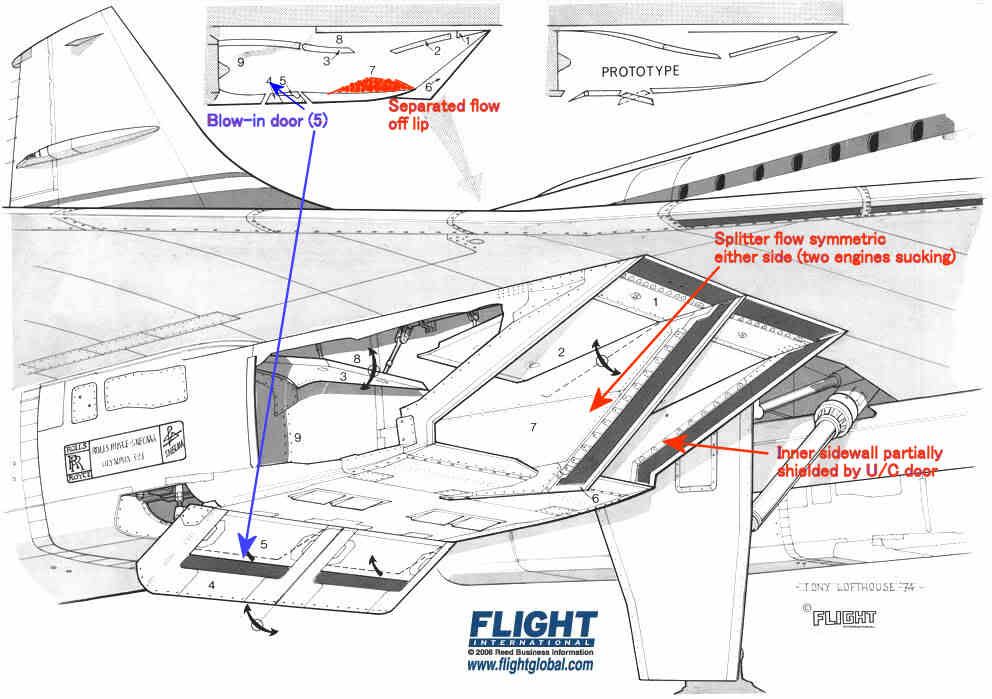
The intake leading edges were all sharp, so the flow would separate if subjected to a high AoA. The upper lip was protected a little by the wing leading edge, and we were obliged to modify the prototype LE ahead of the intakes to prevent underwing vortices developing at low AoA in cruise which also helped a bit.
The lower lip had a substantial separated flow 'bubble' at low forward speed as shown in red, but this cleared up quite quickly as the aircraft gathered speed. It was'cured' by the blow-in doors.
The inner sidewalls were shielded by the landing gear doors, so the AoAs on the sidewall on that side were quite modest.
The splitter was of course subject to equal flow demands on either side so the flow over that was pretty well symmetric.
That leaves the two outer sidewalls which, look for all the world like highly swept delta wings with sharp LEs mounted vertically.
Like all such wings when operated at high AoA they develop powerful vortices on the 'leeward' side. Looking back towards the engine the vortex on #4 engine was anticlockwise and that on #1 was clockwise. [Hope I got that one the right way round ]
]
The OL593 rotates clockwise looking aft so the induced incremental AoA on the compressor blades was different on #1 and #4. The difference was enough to trigger some mild blade vibration - hence the rpm restriction until the intake capture was good enough to reduce the vortex strength.
I don't think there is any published explanation, but maybe this will help.
Basically the problem with #4 intake was that it was on the RHS of the airplane. We are talking about low speed right? and especially zero forward speed when the engine is trying to suck as much air as it can get from wherever it can get it. That means that the induced angle of attack on all the intake leading edges is going to be high.
The best drawing I can find that shows the flow into the right hand pair is this
The intake leading edges were all sharp, so the flow would separate if subjected to a high AoA. The upper lip was protected a little by the wing leading edge, and we were obliged to modify the prototype LE ahead of the intakes to prevent underwing vortices developing at low AoA in cruise which also helped a bit.
The lower lip had a substantial separated flow 'bubble' at low forward speed as shown in red, but this cleared up quite quickly as the aircraft gathered speed. It was'cured' by the blow-in doors.
The inner sidewalls were shielded by the landing gear doors, so the AoAs on the sidewall on that side were quite modest.
The splitter was of course subject to equal flow demands on either side so the flow over that was pretty well symmetric.
That leaves the two outer sidewalls which, look for all the world like highly swept delta wings with sharp LEs mounted vertically.
Like all such wings when operated at high AoA they develop powerful vortices on the 'leeward' side. Looking back towards the engine the vortex on #4 engine was anticlockwise and that on #1 was clockwise. [Hope I got that one the right way round
]
The OL593 rotates clockwise looking aft so the induced incremental AoA on the compressor blades was different on #1 and #4. The difference was enough to trigger some mild blade vibration - hence the rpm restriction until the intake capture was good enough to reduce the vortex strength.
2nd Sep 2012, 12:06
permalink Post: 1681
Don't know much about radio altimeters. First thoughts were that it was some sort of vortex generator, but seems a funny place to have one. Second thoughts were that the 'vane' standing off the surface was there to generate some sort of suction (the 'hole' seems to be on the leeward side) to make sure that the inside did drain in all conditions.
14th Oct 2013, 15:06
permalink Post: 1722
Quote:
|
The ORIGINAL design for the reheat was done by SNECMA, but due to them getting into all sorts of trouble with the fuel injection system and flame stabilisation, Rolls-Royce baled them out, and it became a Rolls-Royce/ SNECMA design.
ref heritageconcorde.com Does anyone have any details on the 'joint' development alluded to above? |

The problem apparently was that flame stabilisation operating in "contingency" rating was sensitive to the point that every engine had to be checked, so there was a lot of engine plus reheat testing, most of which was done at Patchway. The solution was addition of some form of 'spike' at various points on the spray bar (my informant wasn't very specific). It sounded like a sort of vortex generator cum chine that gave the flame somewhere to latch onto. The development process was, as you suggested, a joint activity.