June 19, 2025, 02:40:00 GMT
permalink Post: 11905665
Shirtsleeves/watches etc. can get caught, lift switch.
Very poor design. Would not pass `military-muster.`
Ours:

787:

Subjects
Fuel (All)
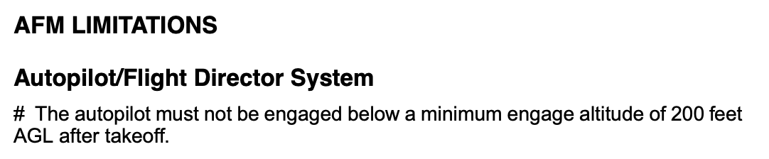
Fuel Cutoff Switches
Switch Guards
Links are to this post in the relevant subject page so that this post can be seen in context.
The thread is closed so there are no user likes are available and no reply is possible.
June 19, 2025, 02:43:00 GMT
permalink Post: 11905667
B777:
B787:
Subjects: None
The thread is closed so there are no user likes are available and no reply is possible.
June 19, 2025, 03:36:00 GMT
permalink Post: 11905682

Subjects
Switch Guards
Links are to this post in the relevant subject page so that this post can be seen in context.
The thread is closed so there are no user likes are available and no reply is possible.
June 19, 2025, 12:01:00 GMT
permalink Post: 11905926

Subjects
Condolences
Honeywell
Special Airworthiness Information Bulletin
Links are to this post in the relevant subject page so that this post can be seen in context.
The thread is closed so there are no user likes are available and no reply is possible.
June 19, 2025, 12:34:00 GMT
permalink Post: 11905954
Assembly to prevent failure of the hydraulic pump at low air speed. The RAT Assembly provides an emer-
gency source of electrical and hydraulic power for the primary flight control if the left, center and right main
hydraulic systems fail. Loss of the RAT Pump and Control Module Assembly could lead to loss of control
of the airplane when emergency power from RAT Assembly is needed. If this change is not incorporated
on the RAT Assembly and hydraulic power is lost on the left, right and center main hydraulic systems, then
the RAT Assembly may not provide sufficient hydraulic power which could result in the loss of many critical
control systems that are necessary for safe flight.

787 RAT hydraulic pump location
Last edited by Senior Pilot; 19th June 2025 at 12:40 . Reason: Image
Subjects
Generators/Alternators
Hydraulic Failure (All)
RAT (All)
RAT (Electrical)
Links are to this post in the relevant subject page so that this post can be seen in context.
The thread is closed so there are no user likes are available and no reply is possible.
June 19, 2025, 13:13:00 GMT
permalink Post: 11905973
Sorry to disagree.

Have a few of that type here, so here's an up close pic of the toggle / cam end. Even applying as much force as possible, the switch does not skip the cam to the alternate position. The toggle must be lifted, and is quite heavily spring loaded. As far as I can see, there is no way that such a switch would change position, other than by lifting the toggle, which is, in fact, the way they are designed to work.
Subjects: None
The thread is closed so there are no user likes are available and no reply is possible.
June 19, 2025, 13:25:00 GMT
permalink Post: 11905981

Other types are different. The A350/A380 do have an electric-only RAT with adequate electric flight controls.
The A320/A330 have a hydraulic-only RAT with a separate hydraulic-driven electrical generator. The 757/767 are similar except the generator is optional.
Some used an electric RAT to drive an electric hydraulic pump.
Be careful when attempting to transfer knowledge from one type to another.
Last edited by Saab Dastard; 19th June 2025 at 16:45 . Reason: Reference to deleted post removed
Subjects
FCOM
Generators/Alternators
Hydraulic Failure (All)
RAT (All)
Links are to this post in the relevant subject page so that this post can be seen in context.
The thread is closed so there are no user likes are available and no reply is possible.
June 19, 2025, 15:52:00 GMT
permalink Post: 11906088
For the avoidance of doubt, the above is a technical observation on the switch type NOT a causation theory for this accident.

Subjects
Condolences
Honeywell
Special Airworthiness Information Bulletin
Links are to this post in the relevant subject page so that this post can be seen in context.
The thread is closed so there are no user likes are available and no reply is possible.
June 19, 2025, 16:03:00 GMT
permalink Post: 11906094
There is no conflict. Simply a lack of ADS-B data.
Edit - Add the ADS-B data points graphic that I had posted June 17.

Subjects
ADSB
Links are to this post in the relevant subject page so that this post can be seen in context.
The thread is closed so there are no user likes are available and no reply is possible.
June 19, 2025, 17:03:00 GMT
permalink Post: 11906148

Draw your own conclusions.
Personally, I trust there were no issues.
Subjects: None
The thread is closed so there are no user likes are available and no reply is possible.
June 19, 2025, 17:09:00 GMT
permalink Post: 11906156
The 787 is operated throughout the middle East where temperatures far exceed that experienced in this instance.
Last edited by T28B; 19th June 2025 at 17:15 . Reason: format and spelling assistance
Subjects: None
The thread is closed so there are no user likes are available and no reply is possible.
June 19, 2025, 17:12:00 GMT
permalink Post: 11906161
That's a TL series switch with 4 poles (the "4" in "4TL"), a "type D" lock (meaning locked out of centre position per the Honeywell data sheet - the "D" in "3D." This is a photo of one:

You can find the manufacturer's datasheet here: https://octopart.com/datasheet/4tl83...ywell-25749542
Problems with critical switches aren't new on 787-8s. For instance, in addition to the SAIB above, there's this AD: https://www.federalregister.gov/docu...pany-airplanes
Looking at the photo above, it isn't just wear that's potentially an issue, but foreign object impingement. There don't appear to be gaitors fitted to these switches in the 788, so the locking mechanisms are potentially susceptible to a build-up of material if not kept clean. There are a range of other failure modes possible, whilst the SAIB specifically describes found-in-the-field problems with these switches.
Yes, they're chunky, and very positive when new. That doesn't mean they shouldn't be discussed.
Subjects
Air Worthiness Directives
Honeywell
Special Airworthiness Information Bulletin
Links are to this post in the relevant subject page so that this post can be seen in context.
The thread is closed so there are no user likes are available and no reply is possible.
June 19, 2025, 20:02:00 GMT
permalink Post: 11906274
UPS had a triple engine shutdown on A RR Tay engined 727. The crew got one started in the nick of time and were able to land at KORD. I know the crewmemebers.
An old post from 2004,

Subjects
Engine Failure (All)
Engine Shutdown
Links are to this post in the relevant subject page so that this post can be seen in context.
The thread is closed so there are no user likes are available and no reply is possible.
June 19, 2025, 21:35:00 GMT
permalink Post: 11906349
I'm commenting to make that point but also to link the videos and the FR-24 dataset - (below with my deltas for height/time added)

Extract from FR24 csv dataset
As noted in both threads to date everything was normal until it wasn't - the two values for fpm above are subject to FR24 variance of +/- 25' so even these suggest a normal climb at this stage of flight ca 2,000fpm. FR24 Lat/Longs all follow the centre line.
On this data the climb stops at around 70' AGL and electrical failure around 2s later. Again, as noted in the threads, this aligns with when gear up might have been expected. If the climb stopped because of fuel shutoff then 2s for spool down to electrical failure isn't out of the question.
Looking at the two videos.
The CCTV video indicates a total flight time, from rotation, of about 32s, subjectively levelling off ~14s after rotation.
The rooftop video has a flight time ~14s suggesting the video starts ~18s after rotation.
The rooftop video evidences the RAT as deployed from the beginning - meaning it must have been deployed by at least 16s after rotation - which aligns with the ADS-B indicated electrical failure.
If the forward flight recorder really is being sent to the US for recovery then it's reasonable to assume that the rear recorder contains nothing after the electrical failure and they are hoping the forward recorder captured something from the cockpit in the final 16s.
I don't have any experience of flight deck CRM but I don't see how those timings allow problem identification/misidentification and subsequent action - ie it wasn't down to the crew.
However:
The maximum aircraft height in the CCTV video, as judged by wingspan, appears higher than 71' - though it is certainly less than a wingspan height at the beginning of the rooftop video.
I haven't seen, in the threads, any statement of what happens on the flight deck with a total electrical failure - is it a 4s blackout whilst the RAT deploys and systems restart? - or are there batteries that keep something alive?
Subjects
ADSB
CCTV
DFDR
Electrical Failure
FADEC
FlightRadar24
RAT (All)
RAT (Deployment)
Relight
Links are to this post in the relevant subject page so that this post can be seen in context.
The thread is closed so there are no user likes are available and no reply is possible.
June 19, 2025, 21:52:00 GMT
permalink Post: 11906364
That's a TL series switch with 4 poles (the "4" in "4TL"), a "type D" lock (meaning locked out of centre position per the Honeywell data sheet - the "D" in "3D." This is a photo of one:
You can find the manufacturer's datasheet here: https://octopart.com/datasheet/4tl83...ywell-25749542
Problems with critical switches aren't new on 787-8s. For instance, in addition to the SAIB above, there's this AD: https://www.federalregister.gov/docu...pany-airplanes
Looking at the photo above, it isn't just wear that's potentially an issue, but foreign object impingement. There don't appear to be gaitors fitted to these switches in the 788, so the locking mechanisms are potentially susceptible to a build-up of material if not kept clean. There are a range of other failure modes possible, whilst the SAIB specifically describes found-in-the-field problems with these switches.
Yes, they're chunky, and very positive when new. That doesn't mean they shouldn't be discussed.
Subjects
Air Worthiness Directives
Honeywell
Special Airworthiness Information Bulletin
Links are to this post in the relevant subject page so that this post can be seen in context.
The thread is closed so there are no user likes are available and no reply is possible.
June 20, 2025, 02:02:00 GMT
permalink Post: 11906517

Both engines failed: yup, both engines have failed.
Triple hydraulic pressure low: either you've been hit by a SAM/uncontained engine failure causing massive fluid leaks, or both engine driven pumps have failed (likely because the engines have failed) and all four electric pumps have failed (because the engines have failed).
Loss of all electric power to flight instruments both sides: total AC electric loss, and I think battery/static inverter too? Given four generators and four buses, either massive electrical failure (swimming pool in E&E bay) or engines have failed. Note failure of an individual contactor that can tie two buses together should not cause a quad-bus outage.
Loss of all four electric motor pumps: total AC failure, see above.
Subjects
Electrical Failure
Engine Failure (All)
Engine Shutdown
Generators/Alternators
Hydraulic Failure (All)
Links are to this post in the relevant subject page so that this post can be seen in context.
The thread is closed so there are no user likes are available and no reply is possible.
June 20, 2025, 02:13:00 GMT
permalink Post: 11906520
Both engines failed: yup, both engines have failed.
Triple hydraulic pressure low: either you've been hit by a SAM/uncontained engine failure causing massive fluid leaks, or both engine driven pumps have failed (likely because the engines have failed) and all four electric pumps have failed (because the engines have failed).
Loss of all electric power to flight instruments both sides: total AC electric loss, and I think battery/static inverter too? Given four generators and four buses, either massive electrical failure (swimming pool in E&E bay) or engines have failed. Note failure of an individual contactor that can tie two buses together should not cause a quad-bus outage.
Loss of all four electric motor pumps: total AC failure, see above.
Subjects
Electrical Failure
Engine Failure (All)
Engine Shutdown
Generators/Alternators
Hydraulic Failure (All)
Links are to this post in the relevant subject page so that this post can be seen in context.
The thread is closed so there are no user likes are available and no reply is possible.
June 20, 2025, 10:07:00 GMT
permalink Post: 11906749

Subjects
FlightRadar24
Links are to this post in the relevant subject page so that this post can be seen in context.
The thread is closed so there are no user likes are available and no reply is possible.
June 20, 2025, 10:15:00 GMT
permalink Post: 11906759

The black rubber cap protects a multi-pin connector.

The white cylinder is an underwater location transmitter.

The forward EAFR has its own backup power.
Source: https://www.geaerospace.com/sites/de...rder-3254F.pdf
Subjects
EAFR
Links are to this post in the relevant subject page so that this post can be seen in context.
The thread is closed so there are no user likes are available and no reply is possible.
June 20, 2025, 17:04:00 GMT
permalink Post: 11907092

Edit to add - I have made no attempt to correct the raw ADS-B altitude data. There is no need to make any correction to see altitude gain.
I've had a bit more time to analyse now.
Those ADS-B data points (and particularly the rate of deceleration) are EXACTLY what you would expect to see from a total engine failure at or very shortly after TAKE-OFF
(it implies a 13:1 L/D which must be pretty close for gear down and flaps 5).
It places takeoff at 700m before the runway end @ ~185kt
Based on those, max altitude was c250ft @ 140kt (or the equivalent total energy equivalent), 500m after the end of the runway.
13:1 L/D would also get you groundspeed on impact of 120kt
Do those numbers make sense?
Subjects
ADSB
Engine Failure (All)
Links are to this post in the relevant subject page so that this post can be seen in context.
The thread is closed so there are no user likes are available and no reply is possible.