June 17, 2025, 11:01:00 GMT
permalink Post: 11904160
After I have read the whole thread, I think most of the community agrees about a lack of engine thrust being the cause of the crash. Searching in that direction, I'm trying to "think out of the box", discarding the usual suspects (birds ingestion, TCMA, human mistake...), and to find a plausible single point of failure among the various subsystems involved. I was thinking of reversing the causality of the event, i.e. exploring a case where the engines would have behaved unexpectedly because of a major electrical failure, instead of the already explored case where both powerplants went AWOL first.
Therefore, I have a couple questions for tdracer / fdr / other informed contributors (BTW, fantastic contribution guys, please keep the good info coming):
1. From the scarce info available, is it reasonable to conclude that the engines were totally shut down? Could they have just been set to idle or reduced thrust instead?
2. In the second case, if (and that's a big IF) a major electrical failure happened first (which could have triggered RAT deployment), and considering this plane is a FBW aircraft, could there exist a case where the FADECs would command idle thrust -- or significant thrust reduction -- because they receive invalid input data from the throttle controls? Kind of a garbage in-garbage out case?
The associated scenario would be: major electrical fault (with subsequent RAT deployment) -> major protocol disturbance on ARINC/AFDX buses -> FADECs detect invalid data from the controls -> FADECS enter some kinf of safe mode and command reduced or idle thrust.
Does it make sense or is it pure fantasy?
Subjects
Electrical Failure
FBW
RAT (All)
RAT (Deployment)
Thread Moderation
Links are to this post in the relevant subject page so that this post can be seen in context.
The thread is closed so there are no user likes are available and no reply is possible.
June 17, 2025, 15:52:00 GMT
permalink Post: 11904368
To clarify, you are saying that the throttle position sensors are wired directly to the FADEC, and nothng else ?.
Subjects
ARINC
FADEC
Links are to this post in the relevant subject page so that this post can be seen in context.
The thread is closed so there are no user likes are available and no reply is possible.
June 17, 2025, 17:41:00 GMT
permalink Post: 11904452
Obviously enough, this isn't a real circuit diagram, but shouldn't this link be removed from the patent drawing?

Odd link in TCMA patent drawing
Subjects
High Pressure Shutoff Valve
RUN/CUTOFF
Links are to this post in the relevant subject page so that this post can be seen in context.
The thread is closed so there are no user likes are available and no reply is possible.
June 18, 2025, 17:12:00 GMT
permalink Post: 11905370
Subjects
High Pressure Shutoff Valve
Links are to this post in the relevant subject page so that this post can be seen in context.
The thread is closed so there are no user likes are available and no reply is possible.
June 19, 2025, 12:34:00 GMT
permalink Post: 11905954
Assembly to prevent failure of the hydraulic pump at low air speed. The RAT Assembly provides an emer-
gency source of electrical and hydraulic power for the primary flight control if the left, center and right main
hydraulic systems fail. Loss of the RAT Pump and Control Module Assembly could lead to loss of control
of the airplane when emergency power from RAT Assembly is needed. If this change is not incorporated
on the RAT Assembly and hydraulic power is lost on the left, right and center main hydraulic systems, then
the RAT Assembly may not provide sufficient hydraulic power which could result in the loss of many critical
control systems that are necessary for safe flight.

787 RAT hydraulic pump location
Last edited by Senior Pilot; 19th June 2025 at 12:40 . Reason: Image
Subjects
Generators/Alternators
Hydraulic Failure (All)
RAT (All)
RAT (Electrical)
Links are to this post in the relevant subject page so that this post can be seen in context.
The thread is closed so there are no user likes are available and no reply is possible.
June 21, 2025, 16:52:00 GMT
permalink Post: 11907864
https://www.biobor.com/wp-content/up...ation-IATA.pdf
If we assume 50 tonnes fuel load a 100ppmw biotreatment will be 5kg of biocide total in all tanks.
The GEnx-1B will burn about 4,5kg/s fuel each on a take off run (give or take a bit) so 9kg/s in both donks for about 20s until rotate.
So the total nominal biocide dose could be pumped in about half a second through both engines on take off power if it where not mixed at all and arrives in both engines at the same time.
This gives you an idea that with the nominal amount of biocide dose not much could have happened. If biocide is the source of this dual EFATO than an extreme overdose in addition to wrong application preventing mixture with the fuel had to be the case.
First, the problem involves the valves (notably but not exclusively FMV and FSV), not the combustion of the product:


These "rpm oscillations", leading to substantial loss of thrust, could as well have occurred simultaneously, and 81 seconds (for the RH engine) is an awfully long time. According to the report, Kathon FP1.5 is not used anymore for biocide treatment, but another contributor ( nachtmusak , who seems to be a petrol specialist) suggested that other products may have similar effects .
Therefore, regarding the case we are discussing at large (thanks again, mods!), I think we shouldn't overlook the hypothesis of fuel contamination by biocide, since it is a single point of failure (among a very limited number of SPoFs) from a system analysis point of view.
Subjects
EFATO
Fuel (All)
Thread Moderation
Links are to this post in the relevant subject page so that this post can be seen in context.
The thread is closed so there are no user likes are available and no reply is possible.
June 21, 2025, 18:23:00 GMT
permalink Post: 11907918
According to the AMM calculation formula, the concentration ratio of the additional biocide treated fuel is calculated to be about 250 ppm in the left tank and about 285 ppm in the right tank. However, there was no record of the calculation of the concentration ratio of the biocide and the dosage amount. It is desirable to keep these records because they are considered to be important for traceability of maintenance work.
Subjects: None
The thread is closed so there are no user likes are available and no reply is possible.
June 21, 2025, 19:20:00 GMT
permalink Post: 11907962
In case of the Safran FADEC 3 this is not actually what we're dealing with. It uses something called an FPGA (Field Programmable Gate Array) which is a very different beast to what we are used to dealing with.
(...)
Unsurprisingly this is rather inconvenient when dealing with the real world and especially when dealing with volatile physical processes that need monitoring. Like a modern turbine engine.
Enter the FPGA.
While it is programmable what that actually means is that (at a very high level) you can build a thing called a truth table, that means a definitive mathematical mapping of input states to output states. Unlike our sequential CPU driven system an FPGA will be able to perform its entire logic every time it is asked to do so. We don't have to wait for our happy check to perform any other check.

... which is part of a larger Powerpoint presentation by Ansys , explaining that these products are developed with SCADE development workbench, generating either Ada or C code, and that the resulting code runs under a microkernel realtime operating system:

Now, obviously enough, a CPU can be embedded in an application-specific FPGA, but it would still execute machine code. And from my experience in other embedded systems development, current CISC or RISC CPUs have more than enough computation power to implement command and control on a modern turbofan.
Subjects
FADEC
Links are to this post in the relevant subject page so that this post can be seen in context.
The thread is closed so there are no user likes are available and no reply is possible.
July 12, 2025, 10:33:00 GMT
permalink Post: 11920418
And while I was painfully crawling the thread, I noticed the following picture about an "undesirable condition":
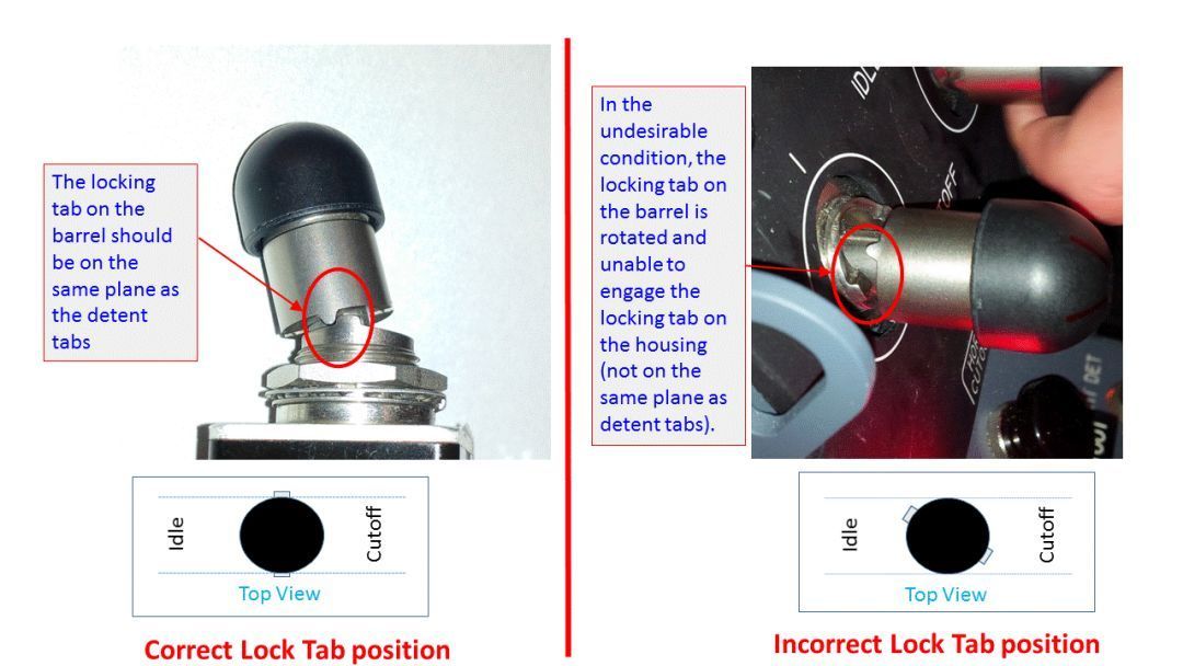
Incorrect lock tab position on fuel cut-off switch
If this incorrect mounting is actually possible, it would possibly remain unnoticed from the pilots (normal "pull-up then move" action is unaffected), but it would cancel the protective function of the so-called "locking tab", and even limit the travel of the switch handle in both directions, making it more vulnerable to an undesired change of state.
The photos above seem convincing enough, but I'd be very grateful for an informed opinion on this assembly mistake. Even if this is possible, the probability of both switches being unexpectedly snapped seems very remote to say the least, but not as remote as previously estimated.
Subjects
Fuel (All)
Fuel Cutoff
Fuel Cutoff Switches
SAIB NM-18-33
Special Airworthiness Information Bulletin
Links are to this post in the relevant subject page so that this post can be seen in context.
Reply to this quoting this original post. You need to be logged in. Not available on closed threads.
July 12, 2025, 22:20:00 GMT
permalink Post: 11920840
Not a pilot, but electronics engineer here: I finally understood what's wrong with the "defective" switches: on such a switch, if you raise it up (to change its position) and you turn it slightly clockwise or counterclockwise before releasing it, it will operate normally, but the detents are now "crossing" the lock tab, and this one doesn't prevent a move-it-without-raising-it-first action anymore. As far as I can tell from the position of the switches, you have to extend your arm sideways and put some effort in your wrist to activate these switches: chances are that such a movement results in some amount of rotation.
By the way, I find that the "check" recommended in the bulletin for a switch suspected from being "defective" is incredibly misleading. It will possibly detect a switch where the cap has already been turned, resulting in a misalignment of the lock tab with the detents, but it won't detect a switch waiting for a turn to put it in the dangerous configuration. The "check" should be "pull on the cap to raise it, try to turn it clockwise or counterclockwise while raised: if it can be turned, it's defective".
May I add that I consider the probability of such a scenario as very very thin, but I wanted to emphasize the fact that we must keep our minds open, instead of jumping to conclusions too early.
Subjects
CVR
Fuel (All)
Fuel Cutoff Switches
Fuel Cutoff Switches (detent)
Links are to this post in the relevant subject page so that this post can be seen in context.
Reply to this quoting this original post. You need to be logged in. Not available on closed threads.