August 19, 2010, 11:16:00 GMT
permalink Post: 5879669
Stupid, you? no way!! (Besides, I'm Mr Stupid of the aviation world, that's my title
 ). The thing is, out here in the world of flying machines, there are almost an infinite number of questions (and hopefully answers too). This applies to just about all aircraft from the Wright Flyer up!!.

Keep asking away, there are so many of us Concorde 'nuts' out here who are more than happy to help out/bore the socks off you.
Fuel burns: The problem was that when flying slow/taxying, Concorde was an extreme gas guzzler, even when idling each engine burnt around 1.1 tonnes/hour (so every 15 minutes after push back meant over a tonne gone). A typical taxi fuel would be around 1.4/1.5 tonnes, depending on the runway in use on the day. I'd have to leave it to some of my pilot/F/E friends to remember some of the specific fuel burns after take off etc, but I can at least give you some interesting consumption figures:
At the beginning of the take off roll, each engine would be burning around 21 tonnes/hour. (Made up of around 12 T/Hr dry fuel (Fe) and 9T/Hr afterburner (reheat to us Brits) fuel (Fr). As Fr was scheduled against Fe, as a function of inlet total temp (T1) by the time V2 was reached (around 220 KTS) the rising T1 has pushed the total fuel flow (Ft) up to a staggering 25 tonnes/hour/engine. As i've pointed out before in previous topics, although the afterburner only gave us a 17% improvement in take off thrust, it was responsible for around an 80% hike in fuel burn. (Hence that is whay it was only used sparingly). However when reheat was used for transonic acceleration, it used a dramatically reduced schedule (roughly a 60% rise in fuel flow) , so it was not quite as scary. The afterburner would be lit at the commencement of the acceleration (0.96 Mach) and cancelled completely at 1.7 Mach. After this time the aircraft would accelerate on dry power only up to mach 2 and beyond. (The cooler the temperature the quicker the time to Mach 2). On an ISA+ day, it sometimes felt that the aircraft was flying through cold porridge, and could take quite a while to get to Mach 2 after reaheat cancellation, where as on a nice ISA - day, she would go like a bat out of hell, and the AFCS would have to jump in to prevent overspeeds.
Before I hit some more numbers, let me say that with Concorde, TOC = TOD!! After reheat cancellation at Mach 1.7, the aircraft would be at FL 430. The aircraft would climb at an IAS of 530 KTS until Mach 2 was reached at fractionally over FL500. From then on the aircraft would cruise/climb as fuel was burnt, up to a maximum of FL600. On warmish days (eg. the North Atlantic) TOD would typically be around FL570-580. On a cool day (the lowes temperatures would of course be reached in the more tropical regions; the LGR-BGI sector encountered this), FL 600 would be reached easily and she would love to climb some more. BUT, the aircaft was only certificated to 60,000' with passengers onboard, for decompression emergency descent time reasons, and so we were stuck with it. The pity is of course, the fuel burn would have been improved, but we never were able to take advantage of this. On test flights however, the aircraft would routinely zoom climb to FL 630. On her maiden flight, aircaft 208 (G-BOAB) reached an altitude of 65000'; the highest recorded Concorde altitude was on one of the French development aircraft, which achieved 68,000'. On a technical point, the analog ADC's were 'only' calibrated to 65,000'.
Anyway, back to some figues; at Mach 2, 50,000', the typical fuel burn per engine would be around 5 tonnes/hour, falling to around 4.2 tonnes/hour at 60,000'.
THE NOSE You are quite correct in your assumption, there were two positions of droop: 5 deg's for taxi/take-off and low speed flight and 12.5 deg's for landing. The glazed visor retracted into the nose and could ONLY be raised once the nose was fully up, and had to be stowed before the nose could move down. There were 2 emergency nose lowering sysyems; one using stby (Yellow) hydraulics and a free-fall system. Free-fall would drop the nose all the way to 12.5 deg's, the visor free falling into the nose also.
Last edited by M2dude; 19th August 2010 at 12:40 . Reason: mistooks
Subjects
ADC (Air Data Computer)
AFCS (Automtic Flight Control System)
Afterburner/Re-heat
Depressurisation
FL600
Fuel Burn
G-BOAB
IAS (Indicated Air Speed)
Intakes
Transonic Acceleration
V2
Visor
Links are to this post in the relevant subject page so that this post can be seen in context.
Reply to this quoting this original post. You need to be logged in. Not available on closed threads.
August 24, 2010, 23:33:00 GMT
permalink Post: 5890423
Concorde had an ENORMOUS number of electronic control boxes, for example the powerplant alone used TWENTY SIX rather heavy computers and control units, all of which used conventional 1970's manufacturing technology. (Although the intake box was a work of art; rows and rows of double sided PCBs completely crammed with TTL chips). This whole entourage literally weighed a ton, and could be easily replaced by four modern relatively light units with multiple redundancy built in). Even the AFCS used a total of sixteen heavy boxes, again these could be reduced to three, for a modern triple channel system. The three INUs and two ADCs (Very heavy units all) could be replaced with a single ADIRU and SAARU. To complete the package two FMCs (which would also furnish autothrottle functions) could be added. A massive weight saving could be made on the FBW system, by removing the bulky mechanical components (the feel and relay jacks as well as all the mechanical control runs and the massive mixing unit under the rear floor). Careful design could easily provide a full authority triplex or quadraplex FBW system. The current controls could be replaced with either an Airbus or Boeing type system, using either a sidestick (Airbus) or retain a conventional control column system (B777/787) using electric backdrive. The pilots can decide this one. A modern databus system would also be required for providing communication and redundancy; ARINC 629 would be MY preferred choice). The wholesale replacement of the various control units and computers, not to forget miles of wiring, as well as some bulky mechanical hardware would in my view save around 3 tonnes or more in weight alone. A now far more accurate control of aircraft systems would also bring major efficiency savings. As far as saving space, that possibly free up a couple of seat rows, if it were all done properly.
We can all dream I suppose
Dude

Subjects
ADC (Air Data Computer)
AFCS (Automtic Flight Control System)
Airbus
Auto-throttle
Boeing
FBW (Fly By Wire)
Intakes
Sidestick
Links are to this post in the relevant subject page so that this post can be seen in context.
Reply to this quoting this original post. You need to be logged in. Not available on closed threads.
August 25, 2010, 21:05:00 GMT
permalink Post: 5892328
The way I understood the story was that they tried to collect as many reasonably reliable spare AICUs for the last few delivery flights, so as not to have to suddenly cancel a flight.
The AICU was right at the top of the list of "unscheduled removals". IIRC the tea maker was second...
"... 'burning' each individual logic gate with a 9v battery." I believe you, thousands wouldn't... Didn't you have at least some sort of programming unit?
I went through a similar exercise around 1976, but at that time at least we had a programming "suitcase", that let you copy the original in RAM, modifiy bit-by-bit with a keyboard, then 'burn' the PROM (or EPROM, by then) 'automatically'. Still took half the night....
Funny in a way how these things have stuck in our memories... But then, yes, Concorde was unique.
I've said this elsewhere, but I don't mind repeating it... in those days, there were two programmes to be part of. One was Apollo, the other was Concorde. And I've had the chance to be part of one of them.
CJ
Subjects
ADC (Air Data Computer)
AICU (Air Intake Control Computer)
British Airways
Intakes
Links are to this post in the relevant subject page so that this post can be seen in context.
Reply to this quoting this original post. You need to be logged in. Not available on closed threads.
August 25, 2010, 22:17:00 GMT
permalink Post: 5892476
The prototypes used a SAGEM/Ferranti system, replaced by a Litton system on the preprods, then Delco on the production aircraft.
There may have been magnetic core in the prototype INS.
As to the AICS (air intakes) and AFCS (automatic flight control), the answer is a definite NO. The AICUs used PROMs (fuse type, not EPROM) and the AFCS was entirely analog.
Some of the systems were even more 'antique'...
The ADC (air data computer) for instance was still largely electro-mechanical.
And those nifty NAV and COMM frequency selectors, that always stand out on cockpit pictures... no electronics at all, just a set of wafer switches, and about thirty wires linking them to the transmitters/receivers.
CJ
Subjects
ADC (Air Data Computer)
AFCS (Automtic Flight Control System)
AICS (Air Intake Control System)
AICU (Air Intake Control Computer)
INS (Inertial Navigation System)
Intakes
Links are to this post in the relevant subject page so that this post can be seen in context.
Reply to this quoting this original post. You need to be logged in. Not available on closed threads.
August 26, 2010, 00:07:00 GMT
permalink Post: 5892703
It's so great to have a Flight Engineer's input into this fascinating thread. Your write up on the complexities of managing the fuel system was something else; the best such description I've ever read. I'm still wetting myself with your story about the E/O coming out of the loo with his trolleys around his ankles after a surge. (Not you I hope
 ).
).
The original air intake that was in use for the first few years of airline operation was as you know far more prone to surging than the later modified intake with the thinned and lowered bottom lip, which was far more stable and forgiving. Not only was the 'new' intake more stable, a new leading edge fitted to the rear ramp as part of the same modification, at a stroke cured the very serious ramp vibration issue, that was causing intake structural problems at lower supersonic Mach numbers. The most impressive change of all was a fuel saving of around 1.5 Tonnes per Atlantic crossing, with even bigger improvements in cooler temperatures. A major software change obviously accompanied this modification.
ChristiaanJ
YEP! I remember now, the ADC/DAC board definitely WAS one of the candidates that were modified.
I think you will find the tale about AICUs being removed after museum delivery flights was more urban myth. The only units that I can remember being removed or relocated were the ground power protection unit, the TCAS processors and the radar transceivers. (BA had retrofitted their aircraft with a superb Bendix system a few years earlier, and the same units (with windshear detection re-enabled) are used on other aircraft types).
As far as ferrite cores are concerned, asked by DozyWannabe , the original Delco C1VAC INS fitted to the BA Concorde aircraft did utilise ferrite cores. These were replaced with CMOS EPROMs when a modification was carried out in the early 90's, in which a navigation database was fitted to the units. The fuel consumed and total fuel remaining indicators definitely used a ferrite core memory. These electronic displays used an internal memory in case of power interrupts. As far as AFCS goes, can you check your records? Although, as you say, a completely analog system (with the exception of the ITEM test computers) I seem to remember that the Safety Flight Control Computer used a ferrite core for the flying control strain gauge null memory. I could be wrong here, but I can't remember any other NVM in use at the time.
Galaxy Flyer
I'll leave it to one of my pilot (or F/E) friends to answer this one it that's OK.
Dude
Last edited by M2dude; 26th August 2010 at 00:20 .
Subjects
ADC (Air Data Computer)
AFCS (Automtic Flight Control System)
AICU (Air Intake Control Computer)
British Airways
Engine surge
INS (Inertial Navigation System)
Intakes
Links are to this post in the relevant subject page so that this post can be seen in context.
Reply to this quoting this original post. You need to be logged in. Not available on closed threads.
September 16, 2010, 10:31:00 GMT
permalink Post: 5937772
At Heathrow when the crew arrived to depart the aircraft, she was already fairly well tested and fired up, systems wise, even to the extent that the INSs were usually aligned (but not put into NAV mode). Now this all helped immensely as far as systems reliability went, but a last minute INS or ADC failure could often still occur, and hit you in the 'you know wheres' when you had least time. Such was the nature of the beast. (But we all loved her
).

Dude
Subjects
ADC (Air Data Computer)
INS (Inertial Navigation System)
LHR
Links are to this post in the relevant subject page so that this post can be seen in context.
Reply to this quoting this original post. You need to be logged in. Not available on closed threads.
September 16, 2010, 14:22:00 GMT
permalink Post: 5938222
Subjects
ADC (Air Data Computer)
C of G
Cabin Crew
Filton
INS (Inertial Navigation System)
LHR
Simulator
Links are to this post in the relevant subject page so that this post can be seen in context.
Reply to this quoting this original post. You need to be logged in. Not available on closed threads.
December 23, 2010, 00:39:00 GMT
permalink Post: 6138601
Digging out the old BAe conversion course notes:
The "Anti-Stall" (SFC) 1&2 sytems offered:
Super Stab: Increased authority of pitch autostab as incidence increased above 13.5 degrees - proportional to pitch rate and incidence angle - and a nose down pitch trim with a Vc (CAS) deceleration with incidence > 13.5
Stick "Wobbler": the "unmistakable warning" - when incidence > 19 and Vc<270kts the control columns took a life of their own and tried to fling you into the forward galley. Served you right.
Some other high incidence stuff was fed from the ADC rather than the SFC, like:
The ">13.5d incidence" feed to the SFC
CAS (Vc) feed to the SFC
Incidence from 16 to 19 degrees (rate dependant) to get the SFC to feed in up to 4 degree nose down pitch command and the sticj wobbler trigger.
Increase of authority of yaw autostab as incidence > 13.5d
Autotrim inhibit > 14.5d incidence
Stick shaker >16.5d incidence
AP/FD disconnect > 17.5d incidence
There was loads of other technical stuff which engineers understood, but we had to learn by writing diagrams which made sense to us enough to pass the written exam. The bottom line was an aeroplane which flew beautifully, but which you had to understand well, and which you could not tease beyond its limits. If you ignored a limit or an SOP then you reached an unpleasant place far quicker than with the blunties - it was a challenge which rewarded as quickly and as deeply as it punished.
Subjects
ADC (Air Data Computer)
Auto-stabilisation
Auto-trim
Conversion Course
Fuel Burn
Galley
Stick Shaker
Trim
Links are to this post in the relevant subject page so that this post can be seen in context.
Reply to this quoting this original post. You need to be logged in. Not available on closed threads.
December 23, 2010, 03:11:00 GMT
permalink Post: 6138731
A warm welcome to the forum, please keep your most illuminating posts coming!
EXWOK
- Incidence Trim
- Super Stab
- High Incidence Directional Stability
- Auto Trim Inhibit
- Stick Shaker
- A/P disconnect
- Stick Wobbler
- IAS below 140 kts
- Incidence greater than 19\xb0
Purely in the interests of historical accuracy, may I point out that I did once complete a load sheet on a charter flight, but this occasioned such ribald comments from the starboard side of the flight deck, accompanied by ill-suppressed mirth from the maroon Mafioso in the engine room, that I decided in future to delegate all further such calculations to the F/O.

Merry Christmas to all
Bellerophon
Subjects
ADC (Air Data Computer)
Auto-stabilisation
Elevons
IAS (Indicated Air Speed)
Stick Shaker
Trim
Links are to this post in the relevant subject page so that this post can be seen in context.
Reply to this quoting this original post. You need to be logged in. Not available on closed threads.
January 18, 2011, 09:30:00 GMT
permalink Post: 6186581

Clive, you really surprise me when you say you don't think that composites would be used from a future SST, is there a material reason for this? (I'm curious because being of a simple avionic brain, I always assumed composites would be used. But if anyone knows this stuff, you certainly would Clive
).
To answer Mike-Bracknell's original query, as far as avionics goes we can really go to town. For her age Concorde had some truly amazing aircraft systems, for instance the flying controls. To enable mechanical control (both FBW channels failed) there was a highly complex and heavy mixing unit under the rear floor. (To mix pitch and roll pilot mechanical demands into differential elevon demand inputs). This of couse would have to be done away with, as well as the relay jacks and replaced with a pair of side-sticks. (See posts on previous page). A 2 crew operation would obviously be the way to go, but neither desirable or possible in my view when Concorde was designed.
A triplex or quadruplex flying control system (possibly even integrating autoflight) would replace the Concorde collection of several analog boxes with a very small handful of lightweight digital units.. The powerplant control will have major weight savings, just take a look at this lot. 8 Engine Control Units, 4 Bucket Control Units, 2 Nozzle Angle Scheduling Units, 4 Reheat Amplifiers, 8 AICUs, 4 Air Intake Sensor Units and a single Air Intake Test Unit could potentially be replaced by just 4 multi-channel EEC type units. (On subsonic aircraft the EECs are mounted on the engine itself, not sure if that's a good idea for an SST, given the operating environment. Air Data and Navigation systems take a major simplification and weight saving, the 3 INUs and 2 ADCs (All of them straight from the 'rent a hernia' store as far as weight goes), could be replaced by a single ADIRU and a SAARU. The fuel indication/management side of things (2 FQI packs, 2 level switching packs and 3 CG computers) would probably be replaced by a single Fuel Processing unit. Ahhhh perchance to dream
Best regards
Dude
Subjects
ADC (Air Data Computer)
AICU (Air Intake Control Computer)
Afterburner/Re-heat
Avionics
C of G
Elevons
FBW (Fly By Wire)
Intakes
Nozzles
Thrust Reversers
Links are to this post in the relevant subject page so that this post can be seen in context.
Reply to this quoting this original post. You need to be logged in. Not available on closed threads.
January 30, 2011, 09:43:00 GMT
permalink Post: 6212195
The air intake system, although it used Ps from THREE sources (the side static ports and the static ports built into the nose probe; this being a pressure head and not just a pitot as were the side probes) did not apply any individual aircraft corrections, it just made different corrections between side and nose pressure sources (Ps and Pt). Having a digital processor at it's heart, these corrections were signalled by using 'program pins' at the rear of the AICU rack.
As steam driven as the Concorde ADC was, when it came to RVSM implementation in the late 1990s we found that the air data system was in fact superbly accurate, and no modifications to the computers themselves were required. Such a testament to the original superb design.
Best regards
Dude
Subjects
ADC (Air Data Computer)
AICU (Air Intake Control Computer)
British Airways
Intakes
Static Ports
Links are to this post in the relevant subject page so that this post can be seen in context.
Reply to this quoting this original post. You need to be logged in. Not available on closed threads.
January 30, 2011, 12:23:00 GMT
permalink Post: 6212446
However, I have to agree that it only goes to demonstrate yet again, just how good were the original systems and the engineers who designed them.
Nice picture from you too Dude, which raises a couple of questions for me. Why the blind window nearest your wife's camera? And I'm not sure why I've never been aware of it before, but this view shows up some sort of tube mounted atop the fuselage, just in front of the fin. What is that please?
Oh and something that your photograph put in mind. It must be very seldom that even a parked aircraft is actually quiet. Being under AC like that must have been a bit un-nerving for someone so used to being next to Concorde, because she must be virtually silent?
Roger.
Subjects
ADC (Air Data Computer)
Links are to this post in the relevant subject page so that this post can be seen in context.
Reply to this quoting this original post. You need to be logged in. Not available on closed threads.
January 30, 2011, 13:15:00 GMT
permalink Post: 6212514
It was always impressive how similar the ADCs' outputs were compared to the 747 of the same era, and M2Dude has mentioned how the RVSM trials showed their accuracy.
Of course there was always the infamous OAF 'glitch' which threw up false ADS warnings accelerating through M1 which happened regularly during my time on the fleet and was subject to a tech log supplement. It never seemed to affect the machine in any other way. I dunno if she did this from new or it was a result of her nosejob.
Subjects
ADC (Air Data Computer)
Boeing 747
Links are to this post in the relevant subject page so that this post can be seen in context.
Reply to this quoting this original post. You need to be logged in. Not available on closed threads.
January 31, 2011, 11:08:00 GMT
permalink Post: 6214258
The OAF 'Mach 1 glitch' was pretty much from day 1, yonks before the nose job. All we were ever able to establish was that it was definately the ALTITUDE comparator tripping the red ADS master warning I established that one during a test flight. (At FL290 you needed around 350' comparison error between ADCs for at least 3 seconds in order to trip the warning). Trouble was the error was gone so quickly you never got very far. (And the AIDS/FDR system on OAF and OAG only took readings from #1ADC, and not both as was the case with the original 5 aircraft, so the FDR was not much help either).
ChristiaanJ
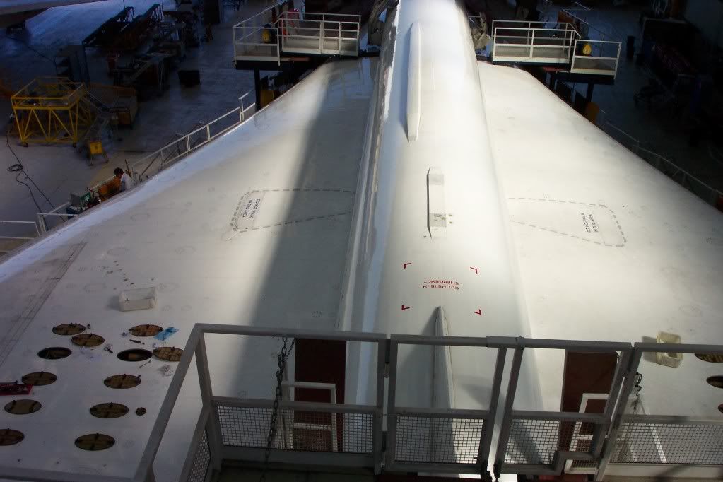
This view from the top of the fin shows it all quite clearly.
Best regards
Dude
Last edited by M2dude; 31st January 2011 at 12:13 . Reason: Correcting age related mistakes
Subjects
ADC (Air Data Computer)
Links are to this post in the relevant subject page so that this post can be seen in context.
Reply to this quoting this original post. You need to be logged in. Not available on closed threads.
April 25, 2011, 06:54:00 GMT
permalink Post: 6410658
As we do not know what the PROPOSED flight regime was, on the part of SFENA and Aerospatiale,we also can not assume that any particular manoeuvr would not have been considered. (But as I said before, it would be great to find out the whole story).
The limited authority for roll autostabilisation (and hence Emergency Flight Control) was of course a very deliberate piece of design. (You could test the Emergency Pilot on the ground at ADC Test 2 (Which simulated several seperate overspeeds, including Vmo +20) and when you put in a roll demand (against some resistance), only the MIDDLE elevons deflected. It really looked wierd on the ICOVOL as well as outside the aircraft.
(To any chaps or chapesses who are not aware, above Vmo+20 KCAS, a system known as OUTER ELEVON NEUTRALISATION was invoked, where any input demand to the outer elevons was met by an automatic equal and OPPOSITE input, that of course completely neutralised the demand, giving a zero OUTER elevon deflection).
Best regards
Dude
Subjects
ADC (Air Data Computer)
Elevons
Vmo
Links are to this post in the relevant subject page so that this post can be seen in context.
Reply to this quoting this original post. You need to be logged in. Not available on closed threads.
November 03, 2011, 00:51:00 GMT
permalink Post: 6786509
 analog electro-mechanical Air Data Computers met RVSM minima quite comfortably when trials were carried out, and that amazed the hell out of most of us. (But a Penny & Giles DADC was still being looked at in the early to mid 90s as a potential ADC replacement).
As far as the expansion joint question goes John, there were several expansion joints all over the aeroplane but I don't recall personally being able to see evidence of thermal expansion anywhere else than the aft flight engineers panel. Perhaps someone else here may know something?.
Best regards
Dude
Subjects
ADC (Air Data Computer)
Expansion
Links are to this post in the relevant subject page so that this post can be seen in context.
Reply to this quoting this original post. You need to be logged in. Not available on closed threads.
November 03, 2011, 17:24:00 GMT
permalink Post: 6787696
It amazes the hell out of me, too.
Steam-powered clockwork describes it quite well.....
I was equally amazed that the ADCs on Sierra Delta still work (as described elsewhere).
CJ
Subjects
ADC (Air Data Computer)
Links are to this post in the relevant subject page so that this post can be seen in context.
Reply to this quoting this original post. You need to be logged in. Not available on closed threads.
April 27, 2012, 17:37:00 GMT
permalink Post: 7159449
2) AFAIK pretty standard:
Q from pitots
S from statics
T from temp probe
Modified by ADC for position error. It's possible that ADC used beta inputs and I'm sure it used alpha inputs to achieve this.
Subjects
ADC (Air Data Computer)
Skin Temperature
Stagnation Point
TAT (Total Air Temperature)
Links are to this post in the relevant subject page so that this post can be seen in context.
Reply to this quoting this original post. You need to be logged in. Not available on closed threads.
April 27, 2012, 20:29:00 GMT
permalink Post: 7159636
2) AFAIK pretty standard:
Q from pitots
S from statics
T from temp probe
Modified by ADC for position error. It's possible that ADC used beta inputs and I'm sure it used alpha inputs to achieve this.
1) So there is a direct temp reading, from the TAT probe. But where is TAT probe? Is it in the needle nose probe that also measures pitot/static for the intake computers? And how many TAT sensors are there (failure of a single one if that's all there is would not be good)?
2) Mach comes from dynamic pressure (pitots), from static ports, and from temp. But what temp? OAT perhaps?
Subjects
ADC (Air Data Computer)
Intakes
Skin Temperature
Stagnation Point
Static Ports
TAT (Total Air Temperature)
Links are to this post in the relevant subject page so that this post can be seen in context.
Reply to this quoting this original post. You need to be logged in. Not available on closed threads.
March 19, 2014, 21:54:00 GMT
permalink Post: 8388573
We chose the components for their environmental tests, and all the AICS components were subjected to acceptance testing when received, which was a bit of a problem sometimes because the BAC goods inwards system was so slow that some of the expensive ADC/DACs that were not quite good enough were returned to Harris, but were out of warranty by the time they were returned. The embargo was not just the 5400 TTL I/Cs but all milspec. components.
Its stretching my memory, but AICU1 was the ADC board, 2-5 were the processor, 6-10 were the prom boards. There was a bought in board (AICU 17 I think) that was supplied by ?????, that processed the sensor unit data.
The AICS was filled with redundancy, as well as the obvious 2 AICUs per intake, and 4 sensor units, the program calculated the output data with dummy inputs - twice, and if these were correct, the proper inputs were used and the result was output to the doors. On the analogue bit there were two channels for each output and at the end one output was compared with the other and if different a fail was produced.
We haven't opened the plan chests with the AICS drawings yet.
As well as the 8 AICUs on G-BOAF, we have the prototype AICU that was used on the AICS systems rig.
Subjects
ADC (Air Data Computer)
AICS (Air Intake Control System)
AICU (Air Intake Control Computer)
G-BOAF
Intakes
Links are to this post in the relevant subject page so that this post can be seen in context.
Reply to this quoting this original post. You need to be logged in. Not available on closed threads.