August 24, 2010, 23:43:00 GMT
permalink Post: 5890440
Loved your AICU stuff. Here's an extract from 'The Concorde Air Intake Control System':
The Control Highway
This highway is a uni-directional databus that carries binary data transmitted by the AISU to it's pair of AICU's. The Control Highway effectively comprises of a single wire, that has transmitted along it multiplexed digital data, clock and address. (In reality this is a twisted wire pair). The AICS Control Highway data word comprises of 64 bits, transmitted at a PRF of (at least by modern standards) an extremely pedestrian 35 Kbits/second.
Sounded mouthwatering in the 1970's though, 35 Kbits/sec' is almost NINE KB/sec'!!!!.
Dude

Last edited by M2dude; 25th August 2010 at 00:11 .
Subjects
AICS (Air Intake Control System)
AICU (Air Intake Control Computer)
Intakes
Links are to this post in the relevant subject page so that this post can be seen in context.
Reply to this quoting this original post. You need to be logged in. Not available on closed threads.
August 25, 2010, 22:17:00 GMT
permalink Post: 5892476
The prototypes used a SAGEM/Ferranti system, replaced by a Litton system on the preprods, then Delco on the production aircraft.
There may have been magnetic core in the prototype INS.
As to the AICS (air intakes) and AFCS (automatic flight control), the answer is a definite NO. The AICUs used PROMs (fuse type, not EPROM) and the AFCS was entirely analog.
Some of the systems were even more 'antique'...
The ADC (air data computer) for instance was still largely electro-mechanical.
And those nifty NAV and COMM frequency selectors, that always stand out on cockpit pictures... no electronics at all, just a set of wafer switches, and about thirty wires linking them to the transmitters/receivers.
CJ
Subjects
ADC (Air Data Computer)
AFCS (Automtic Flight Control System)
AICS (Air Intake Control System)
AICU (Air Intake Control Computer)
INS (Inertial Navigation System)
Intakes
Links are to this post in the relevant subject page so that this post can be seen in context.
Reply to this quoting this original post. You need to be logged in. Not available on closed threads.
November 18, 2010, 12:47:00 GMT
permalink Post: 6069397

 ) this thing was really cutting edge technology at the time, even using a 64 bit data word. The AICS as again I've yawned on about before, was the WORLD's first commercial airborne digital control sysstem, but the Concorde analog stuff in fact worked pretty well indeed.

Galaxy Flyer
As always GF you make your point really well. As far as Concorde went, the very few American (Branniff) pilots who flew her thought she was totally amazing, and the American BA engineers at JFK and IAD absolutely adored the aeroplane.
And back to your 'charriot', the C5 has been a staggeringly successful aeroplane in terms of US service. and is still thriving (big modernisation programme underway). Not bad for an aircraft that entered USAF service in 1969!!!

Regards
Dude
Subjects
AICS (Air Intake Control System)
British Airways
Intakes
JFK
Microprocessor
Nozzles
Links are to this post in the relevant subject page so that this post can be seen in context.
Reply to this quoting this original post. You need to be logged in. Not available on closed threads.
December 22, 2010, 20:40:00 GMT
permalink Post: 6138255
Closed loop
As an example, let's look (very simplified) at how the autopilot maintains a selected altitude.
On the one hand we have the desired altitude as selected on the autopilot controller (here 40,000 ft).
On the other hand we have the true altitude , as measured by the altimeter (let's say 39,000 ft).
We subtract the two to obtain the altitude error (in this case 39,000-40,000=-1,000 ft).
We 'multiply' the altitude error by a factor, the gain (for the discussion, let's assume this gain is 1 degree elevon per 1000 ft altitude error), and send the resulting elevon position command to the elevon.
So, the elevon moves 1\xb0 nose-up, the aircraft starts to climb, the altitude increases and the altitude error decreases until it becomes zero, by which time the elevon position has also returned to zero.
What we have now is a "closed loop" : any deviation from the selected altitude results in an elevon command in the opposite direction, until the deviation is again reduced to zero.
Another commonly used term is "feedback" : any error is fed back in the opposite sense until it's reduced to zero.
The significant figure here is the 'gain'.
If the gain is too small, the autopilot response to a disturbance (say turbulence) will be sluggish ; the aircraft takes too long to return to the desired altitude.
If the gain is too high, a small disturbance will cause the aircraft to start climbing too rapidly, and to overshoot the desired altitude, then descend to correct the new error, etc.
In other terms, the control loop is no longer stable, but starts to oscillate.
Both theory and practice show that the exact value of the gain is not all that critical, a few percent more or less do not markedly change the response of the loop.
Note: a "closed control loop" as described above can be implemented in just about any way you like.
It can be done purely mechanically, with a few clever clockwork mechanisms 'computing' the altitude error and controlling the elevator pneumatically or hydraulically. It's how the earliest autopilots worked.
After that came electromechanical systems, analogue computers and then digital computers... but the principle has remained unchanged.
Open loop
As already described in earlier posts, the situation with the automatic trim is the opposite.
We now need to compute a neutral elevon position from several data, such as Mach number or airspeed, but without any feedback as to whether our computations are correct.
We're now working in "open loop".
To complicate matters... that neutral elevon position is not a simple linear function of Mach and airspeed, but far more complex (see the earlier posted graphs).
And because of the large response of the aircraft to small changes in trim, in particular in the transonic regions, those computations have to be far more accurate : a one degree error is simply not acceptable.
In the end.....
The AICS (air intake control system) also uses several "open loop" functions.
The early development aircraft still had an analogue system, which proved all too soon to be inadequate, so, at a very late stage, it was replaced by a digital system (one of the rare digital systems on Concorde).
The "open loop" functions of the autotrim system initially had the typical "a few" percent" accuracy of the other flight control systems, which, for the autotrim, also proved inadequate.
We managed to "save the furniture" (as they say in French) by using 0.1% components in all the critical computing paths, so the autotrim computers remained analogue until the end.
But, a slide rule is not accurate to 0.1%... So that's when I had to buy my very first pocket calculator.
\xa342 at 1972 prices... just as well the firm paid.
CJ
Subjects
AICS (Air Intake Control System)
Auto-pilot
Auto-trim
Elevons
Intakes
Trim
Links are to this post in the relevant subject page so that this post can be seen in context.
Reply to this quoting this original post. You need to be logged in. Not available on closed threads.
December 23, 2010, 08:54:00 GMT
permalink Post: 6139001
Yes, of course (as ever
 ) you are correct; it was technically a hybrid system: The servo loops, in terms of ramp and spill door demand signals and resolver position feedback signals etc. DID use conventional analogue drive and servo amplifiers within the AICU, it was the massive arithmetic computation UP-STREAM of these that was digital. I always used to like to refer to the AICS as 'an analog front end with a digital brain'. But that's just me
 .
.
But as you say Clive, none of the control law sophistication (including the synthesising the intake face total pressure and local Mach numbers from mainline aircraft raw air data) would have been possible using analog computation.
Best regards
Dude
Subjects
AICS (Air Intake Control System)
AICU (Air Intake Control Computer)
Intakes
Links are to this post in the relevant subject page so that this post can be seen in context.
Reply to this quoting this original post. You need to be logged in. Not available on closed threads.
January 07, 2011, 13:13:00 GMT
permalink Post: 6164710
Gentlemen, I think you will find that 102 did indeed have a totally 'unique' analog intake control system. Not only were the RDCUs (not AICUs in this case chaps) totally different, there were major architectural changes over the prototype system too. Also, although the basic intake structure was the same as 101 and all subsequent aircraft, there was still the prototype approach to local pressure sensing adapted, ie. Intake face total pressure P∞ sensed directly via the infamous 'magic holes' rather than using digitally synthesised values based on mainline aircraft manometric probe, total (pitot)pressure. As 101's intakes only went 'live' in mid-march 1973, I assumed that maybe they (AS) wanted an operative intake system from the outset on 102 when it first flew in January of that year. What puzzled me was why they went for this seemingly enhanced (and expensive) analog system on 102 and not the original system. (As 102 used a production type intake, I guess that they would have to have at least made some changes to the control system ; there was no exotic double hinged 'Dump Door', but the far simpler and elegant 'Spill Door' with integral Aux' Inlet Vane that was known and loved by us all). Rumour had it that AS still wanted to pursue the 'magic holes' solution and were dead against the decision to go digital. (This particular decision was taken in October 1970, which makes the 102 AICS route seem all the more strange).
And ChristiaanJ; what you guys achieved with the MAX CLIMB/MAX CRUISE was nothing short of remarkable. Just about the most exotic (and complex) autopilot mode that I've ever seen, that solved so MANY problems.
(Still the only A/P mode I've ever seen where the Autothrottle is engaged in a speed mode at the same time as the AUTOPILOT
).
Best regards
Dude
Last edited by M2dude; 8th January 2011 at 09:58 . Reason: 'All I want for Christmas is the ability to spell'
Subjects
AICS (Air Intake Control System)
AICU (Air Intake Control Computer)
Auto-pilot
Auto-throttle
Intakes
Links are to this post in the relevant subject page so that this post can be seen in context.
Reply to this quoting this original post. You need to be logged in. Not available on closed threads.
January 18, 2011, 20:53:00 GMT
permalink Post: 6187706
. Here is the one of the 'forward' pages from 'The Concorde Air Intake Control System' publication: (Issue 3 Feb' 2001). There just might be a name or two there that rings a bell.
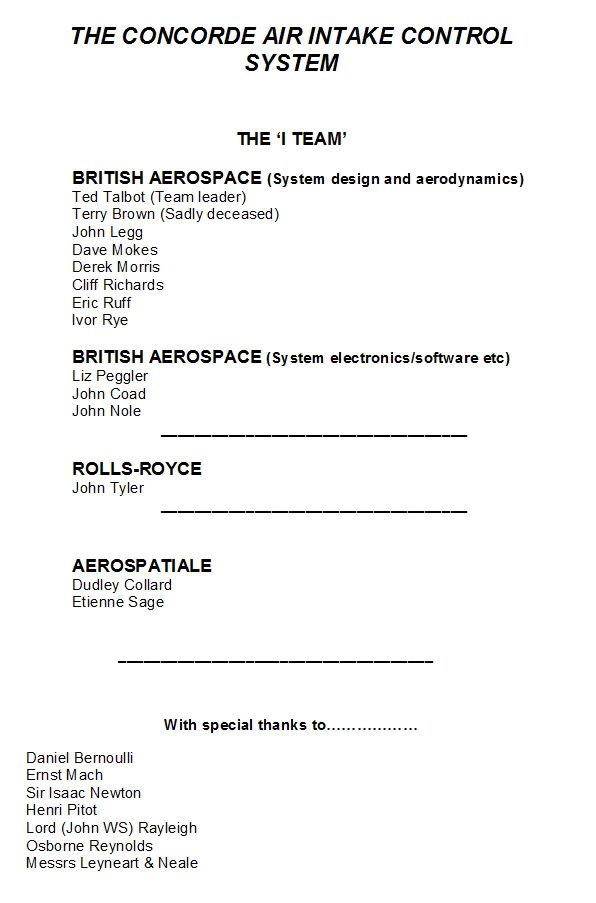
So much was achieved by such a very small team of people. An achievement that was absolutely pivotal to the successful development of Concorde.
With total respect
Dude
Subjects
AICS (Air Intake Control System)
Intakes
Links are to this post in the relevant subject page so that this post can be seen in context.
Reply to this quoting this original post. You need to be logged in. Not available on closed threads.
January 19, 2011, 12:34:00 GMT
permalink Post: 6188841
 I never noticed that one before. I do remember that the late Terry Brown, who was part of your S & C department was a bit of a boat builder as well as being a brilliant aerodynamicist. But all these people were absolute masters of their craft, bad spelling and all, the result being something so very special and unique.
As far as the AICS book goes, there are quite a few copies (methinks a few hundred) that are dotted around; I'll see what I can find and PM you. There were so many of these 'lesser' Concorde works out there that are full of useful information about what made Concorde tick.
Best regards
Dude
.
Subjects
AICS (Air Intake Control System)
Links are to this post in the relevant subject page so that this post can be seen in context.
Reply to this quoting this original post. You need to be logged in. Not available on closed threads.
October 18, 2013, 19:12:00 GMT
permalink Post: 8106029
Subjects
AICS (Air Intake Control System)
Airbus
Filton
Pressurisation
Links are to this post in the relevant subject page so that this post can be seen in context.
Reply to this quoting this original post. You need to be logged in. Not available on closed threads.
March 08, 2014, 18:15:00 GMT
permalink Post: 8360094
So as far as your AICU is concerned - I have handled all the boards extensively.
I first worked on the "A" model - the first manufactured box, followed by "A bar" (logically, not "A").
These did not have the doghouse connector on the front, and in order to see what was going on in the program, we made a strobe unit hard wired to the digital boards, this was followed by the connector on the front and an AICU test box.
When first switched on the whole unit rattled at high speed as all the relays chattered.
I spent several days adding decoupling capacitors on all the boards.
The birds nest chassis wiring was chosen to prevent cross- talk.
This was at the start of 1972, but I can still remember a lot of it.
Someone mentioned a prom change at Casablanca, I carried out a prom change there just before the C of A flight.
I am a volunteer at the Bristol Aero Collection, and we have just received a drawing cupboard with the AICS drawings.
We are at the moment documenting archives. One of the volunteers is Ted Talbot who I used to work with, and has been mentioned in posts.
Feel free to ask questions, I may remember the answers!
Subjects
AICS (Air Intake Control System)
AICU (Air Intake Control Computer)
Avionics
Filton
Links are to this post in the relevant subject page so that this post can be seen in context.
Reply to this quoting this original post. You need to be logged in. Not available on closed threads.
March 08, 2014, 20:39:00 GMT
permalink Post: 8360344
So as far as your AICU is concerned - I have handled all the boards extensively.
I first worked on the "A" model - the first manufactured box, followed by "A bar" (logically, not "A").
These did not have the doghouse connector on the front, and in order to see what was going on in the program, we made a strobe unit hard wired to the digital boards, this was followed by the connector on the front and an AICU test box.
When first switched on the whole unit rattled at high speed as all the relays chattered.
I spent several days adding decoupling capacitors on all the boards.
The birds nest chassis wiring was chosen to prevent cross- talk.
This was at the start of 1972, but I can still remember a lot of it.
Someone mentioned a prom change at Casablanca, I carried out a prom change there just before the C of A flight.
I am a volunteer at the Bristol Aero Collection, and we have just received a drawing cupboard with the AICS drawings.
We are at the moment documenting archives. One of the volunteers is Ted Talbot who I used to work with, and has been mentioned in posts.
Feel free to ask questions, I may remember the answers!
Subjects
AICS (Air Intake Control System)
AICU (Air Intake Control Computer)
Avionics
Filton
Links are to this post in the relevant subject page so that this post can be seen in context.
Reply to this quoting this original post. You need to be logged in. Not available on closed threads.
March 19, 2014, 21:54:00 GMT
permalink Post: 8388573
We chose the components for their environmental tests, and all the AICS components were subjected to acceptance testing when received, which was a bit of a problem sometimes because the BAC goods inwards system was so slow that some of the expensive ADC/DACs that were not quite good enough were returned to Harris, but were out of warranty by the time they were returned. The embargo was not just the 5400 TTL I/Cs but all milspec. components.
Its stretching my memory, but AICU1 was the ADC board, 2-5 were the processor, 6-10 were the prom boards. There was a bought in board (AICU 17 I think) that was supplied by ?????, that processed the sensor unit data.
The AICS was filled with redundancy, as well as the obvious 2 AICUs per intake, and 4 sensor units, the program calculated the output data with dummy inputs - twice, and if these were correct, the proper inputs were used and the result was output to the doors. On the analogue bit there were two channels for each output and at the end one output was compared with the other and if different a fail was produced.
We haven't opened the plan chests with the AICS drawings yet.
As well as the 8 AICUs on G-BOAF, we have the prototype AICU that was used on the AICS systems rig.
Subjects
ADC (Air Data Computer)
AICS (Air Intake Control System)
AICU (Air Intake Control Computer)
G-BOAF
Intakes
Links are to this post in the relevant subject page so that this post can be seen in context.
Reply to this quoting this original post. You need to be logged in. Not available on closed threads.
October 22, 2017, 20:32:00 GMT
permalink Post: 9933310
That myth was amplified substantially by BA removing those "secret" AICUs from the aircraft after the final delivery flights.
The way I understood the story was that they tried to collect as many reasonably reliable spare AICUs for the last few delivery flights, so as not to have to suddenly cancel a flight.
The AICU was right at the top of the list of "unscheduled removals". IIRC the tea maker was second...
The one I know about is the ADC/DAC board (analog-digital and digital-analog converter board). The supply of either ADCs or DACs ran out literaly worldwide, and the board had to be redesigned, requalified and recertified with more recent components, and a new batch manufactured. The cost, for the replacement of that board alone, came to about 3 million euros.
Somebody passed me a photo taken at Casablanca of a table full of AICUs waiting to be programmed... of course every software mod had to be programmed into all eight computers!
"... 'burning' each individual logic gate with a 9v battery." I believe you, thousands wouldn't... Didn't you have at least some sort of programming unit?
I went through a similar exercise around 1976, but at that time at least we had a programming "suitcase", that let you copy the original in RAM, modifiy bit-by-bit with a keyboard, then 'burn' the PROM (or EPROM, by then) 'automatically'. Still took half the night....
Funny in a way how these things have stuck in our memories... But then, yes, Concorde was unique.
I've said this elsewhere, but I don't mind repeating it... in those days, there were two programmes to be part of. One was Apollo, the other was Concorde. And I've had the chance to be part of one of them.
The inter board wiring was random, no harness arrangement other than for power supply. Cross talk was even considered by the design engineers then. Wire wrapped in 30awg OFHC single core cables.
I could go on about a lot of things used in the system as it was also my job to keep a record of all the components and which board they were used on. This also applied to the Sensor Unit, The Test Unit, The Management Control Panel. We were busy Bees in the DO for a few years on AICS. Happy Days
Subjects
ADC (Air Data Computer)
AICS (Air Intake Control System)
AICU (Air Intake Control Computer)
British Airways
Links are to this post in the relevant subject page so that this post can be seen in context.
Reply to this quoting this original post. You need to be logged in. Not available on closed threads.