January 13, 2011, 09:45:00 GMT
permalink Post: 6176684
Really an answer for CliveL, but I'll have a go. The short answer to your question is 'oh yeah, big time'. Total temperature varies with the SQUARE of Mach number and static temperature. Depending on the height of the tropopause itself as well as other local factors, there can be little or no significant variation of static temperature between FL600 and FL700. The 400\xb0K (127\xb0C) Tmo limit was imposed for reasons of thermal fatigue life, and equates to Mach 2.0 at ISA +5. (Most of the time the lower than ISA +5 static air temperatures kept us well away from Tmo). In a nutshell, flying higher in the stratosphere gains you very little as far as temperature goes. (Even taking into account the very small positive lapse above FL 650 in a standard atmosphere). As far as the MAX SPEED bit goes, Concorde was as we know flown to a maximum of Mach 2.23 on A/C 101, but with the production intake and 'final' AICU N1 limiter law, the maximum achievable Mach number in level flight is about Mach 2.13. (Also theoretically, somewhere between Mach 2.2 and 2.3, the front few intake shocks would be 'pushed' back beyond the lower lip, the resulting flow distortion causing multiple severe and surges).
On C of A renewal test flights (what I always called the 'fun flights') we DID used to do a 'flat' acceleration to Mach 2.1 quite regularly, as part of the test regime, and the aircraft used to take things in her stride beautifully. (And the intakes themselves were totally un-phased by the zero G pushover that we did at FL630). This to me was an absolute TESTAMENT to the designers achievement with this totally astounding aeroplane , and always made me feel quite in awe of chaps such as CliveL.

Shaggy Sheep Driver
So glad you are enjoying the thread, and absolutely loved the description of your flight in OAD and your photo is superb. I don't think it is possible to name a single other arcraft in the world that could be happily flown hands off like this, in a turn with 20\xb0 of bank at Mach 2. (One for you ChristiaanJ; The more observant will notice that we are in MAX CLIMB/MAX CRUISE with the autothrottle cutting in in MACH HOLD. Oh, we are in HDG HOLD too
 ).
).
Now for your question
As far as your air conditioning question goes, you needed an external air conditioning truck to supply cabin air on the ground. Not needed in the hangars of course, but come departure time if these trucks were not working, then the cabin could become very warm/hot place indeed (depending on the time of year). Oh for an APU

Best regards
Dude

Subjects
AICU (Air Intake Control Computer)
APU (Auxiliary Power Unit)
Anti-skid
Auto-throttle
Braking
Depressurisation
Engine surge
FL600
Fatigue
Intakes
Landing Gear
N1 (revolutions)
TMO (Temprature Max Operating)
Links are to this post in the relevant subject page so that this post can be seen in context.
Reply to this quoting this original post. You need to be logged in. Not available on closed threads.
January 13, 2011, 11:10:00 GMT
permalink Post: 6176851
On C of A renewal test flights (what I always called the 'fun flights') we DID used to do a 'flat' acceleration to Mach 2.1 quite regularly, as part of the test regime, and the aircraft used to take things in her stride beautifully. (And the intakes themselves were totally un-phased by the zero G pushover that we did at FL630)
As usual Dude you beat me to it! I really must give up having another life

As Dude says, the 'cruise' condition was set by the aircraft specification for transatlantic range on an 85% (ISA +5) day and the chosen mach Number was 2.0 (of which more anon). This gives a Total Temperature of 400.1 deg K. [Dude, I know your pipe-smoking thermodynamicist and he was having you on - he is quite capable of memorising the square/square root of 407.6 or whatever!]
To give margins for sudden changes in ambient temperature (we had to cater for a 21 deg change in one mile) the Mmo was set at 2.04 which matches 400 degK at ISA +1. In theory then we could have flown faster than our chose Mmo at anything colder than this, but there are two limits:
1) The object is not to fly as fast as you can but to fly with minimum miles/gallon. If you have a nice cold day and enough thrust to go either faster or higher which do you choose? For best specific range you go higher every time.
2) The thing that everyone forgets is that civil aircraft have to have margins around their authorised envelope. In Concorde's case these were set principally by the intake limits and engine surge.
Dude also says quite correctly that 101 flew to 2.23M but the production aircraft was limited to 2.13M. Now you may not believe this, but 101 could fly faster than the production aircraft because she (101) leaked like a sieve!.
I doubt I will get away with that without some explanation

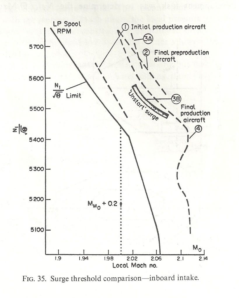
Once you get past a certain Mach Number the airflow into the intake is fixed. The performance (intake pressure recovery and engine face flow distortion) then depends on how this air is shared between the engine and the throat 'bleed'. This bleed was ducted over the engine as cooling air and then exhausted (in principle) throught the annulus formed between the expanding primary jet and the fixed walls of the con-di nozzle. But if you took, or tried to take, more bleed air the intake pressure recovery went up and the primary jet pipe pressure went up with it. This meant that the primary jet expanded more and squeezed the available annulus area which restricted the amount of bleed air one could take.
Obviously if there are alternative exit paths between intake and final nozzle then you can take more bleed air off and the engine face flow distortions will benefit along with the surge margin. 101 was fairly 'leaky' in this respect, particularly around the thrust reverser buckets on the original nozzle design. This meant that 101's intake distortions were lower than the production aircraft so she could fly faster without surge - at least with the first attempt at intake control 'laws'. We managed to tweak most of the margin back eventually. Engine bay leaks were good for surge margin but VERY bad news for m.p.g.!
Here are a couple of diagrams to show what I mean. the first shows the surge lines for the various aircraft variants and also the N1 limiter Dude was talking about. NB: the X-axis is LOCAL Mach Number not freestream. The difference comes from the compression of the underwing flow by the bit of the wing ahead of the intake. Mmo + 0.2 is shown
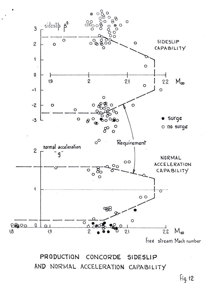
 ">The next shows the surge free boundaries in sideslip and normal acceleration. You can see the zero 'g' capability Dude was enthusing over.
 ">
">
As for 'high speed stall', I don't think we ever contemplated trying it! Our requirements in 'g' capability were defined and that was it. Besides, the aircraft would fly like the proverbial stone-built outbuilding at those sorts of conditions so I don't think one would have been able to get anywhere near a stall in the conventional sense. Stall as commonly defined for subsonics (deterrent buffet) might have been another matter, but I don't remember anything.
Cheers
Last edited by CliveL; 13th January 2011 at 11:17 . Reason: additional explanation
Subjects
AICU (Air Intake Control Computer)
Bleed Air
Engine surge
FL600
Fatigue
Intakes
Mmo
N1 (revolutions)
Nozzles
Sideslip
TMO (Temprature Max Operating)
Thrust Reversers
Links are to this post in the relevant subject page so that this post can be seen in context.
Reply to this quoting this original post. You need to be logged in. Not available on closed threads.
January 18, 2011, 09:30:00 GMT
permalink Post: 6186581

Clive, you really surprise me when you say you don't think that composites would be used from a future SST, is there a material reason for this? (I'm curious because being of a simple avionic brain, I always assumed composites would be used. But if anyone knows this stuff, you certainly would Clive
 ).
).
To answer Mike-Bracknell's original query, as far as avionics goes we can really go to town. For her age Concorde had some truly amazing aircraft systems, for instance the flying controls. To enable mechanical control (both FBW channels failed) there was a highly complex and heavy mixing unit under the rear floor. (To mix pitch and roll pilot mechanical demands into differential elevon demand inputs). This of couse would have to be done away with, as well as the relay jacks and replaced with a pair of side-sticks. (See posts on previous page). A 2 crew operation would obviously be the way to go, but neither desirable or possible in my view when Concorde was designed.
 A triplex or quadruplex flying control system (possibly even integrating autoflight) would replace the Concorde collection of several analog boxes with a very small handful of lightweight digital units.. The powerplant control will have major weight savings, just take a look at this lot. 8 Engine Control Units, 4 Bucket Control Units, 2 Nozzle Angle Scheduling Units, 4 Reheat Amplifiers, 8 AICUs, 4 Air Intake Sensor Units and a single Air Intake Test Unit could potentially be replaced by just 4 multi-channel EEC type units. (On subsonic aircraft the EECs are mounted on the engine itself, not sure if that's a good idea for an SST, given the operating environment. Air Data and Navigation systems take a major simplification and weight saving, the 3 INUs and 2 ADCs (All of them straight from the 'rent a hernia' store as far as weight goes), could be replaced by a single ADIRU and a SAARU. The fuel indication/management side of things (2 FQI packs, 2 level switching packs and 3 CG computers) would probably be replaced by a single Fuel Processing unit. Ahhhh perchance to dream
Best regards
Dude
Subjects
ADC (Air Data Computer)
AICU (Air Intake Control Computer)
Afterburner/Re-heat
Avionics
C of G
Elevons
FBW (Fly By Wire)
Intakes
Nozzles
Thrust Reversers
Links are to this post in the relevant subject page so that this post can be seen in context.
Reply to this quoting this original post. You need to be logged in. Not available on closed threads.
January 18, 2011, 16:56:00 GMT
permalink Post: 6187329
 ).
).

Yes, the 188 was welded stainless and as you said, manufacturing was a pain. I didn't work on that aircraft myself, but one reported episode in the flight test programme is worth a digression off topic. Dialogue (maybe that should be monologue) between aircraft and FT control:
t = 0
Godfrey Auty (test pilot): "Mach ... port engine flamed out"
Silence from ground
t = 10secs
G.A.: "Mach .... starboard engine flamed out"
Silence from ground
t= 15 secs
G.A. "Well for Chrissake say something, even if it's only goodbye!"
Luckily the restart drills worked

After those AICU problems the boss came to see me (I was running the S&C section at the time) and said "Your blokes are doing dynamic simulation of aircraft response (on ANALOGUE computers!), do you think they could simulate the 188 intake control system?". To which of course there is only one answer possible, but that is how the two aerodynamicists who did most of the pioneering work on the Concorde AICU came to work together - Derek Morriss from the 188 project and Terry Brown from the S&C group. And boy were we lucky to have that combination
For the record, if my memory serves, the simulation showed that the 188 problem was hysteresis in the mechanical part of the 188 AICU.
Cheers
Clive
Subjects
AICU (Air Intake Control Computer)
Intakes
Links are to this post in the relevant subject page so that this post can be seen in context.
Reply to this quoting this original post. You need to be logged in. Not available on closed threads.
January 30, 2011, 09:43:00 GMT
permalink Post: 6212195
The air intake system, although it used Ps from THREE sources (the side static ports and the static ports built into the nose probe; this being a pressure head and not just a pitot as were the side probes) did not apply any individual aircraft corrections, it just made different corrections between side and nose pressure sources (Ps and Pt). Having a digital processor at it's heart, these corrections were signalled by using 'program pins' at the rear of the AICU rack.
As steam driven as the Concorde ADC was, when it came to RVSM implementation in the late 1990s we found that the air data system was in fact superbly accurate, and no modifications to the computers themselves were required. Such a testament to the original superb design.
Best regards
Dude
Subjects
ADC (Air Data Computer)
AICU (Air Intake Control Computer)
British Airways
Intakes
Static Ports
Links are to this post in the relevant subject page so that this post can be seen in context.
Reply to this quoting this original post. You need to be logged in. Not available on closed threads.
April 06, 2011, 19:43:00 GMT
permalink Post: 6354590
M2dude gave a good answer on your question in post #1085, so I think I may quote this here again.
The maximum altitude EVER achieved in testing was I believe by aircraft 102 which achieved 68,000'.
Subjects
AICU (Air Intake Control Computer)
Engine surge
Intakes
N1 (revolutions)
Links are to this post in the relevant subject page so that this post can be seen in context.
Reply to this quoting this original post. You need to be logged in. Not available on closed threads.
February 22, 2014, 11:14:00 GMT
permalink Post: 8333226
Subjects
AICU (Air Intake Control Computer)
Links are to this post in the relevant subject page so that this post can be seen in context.
Reply to this quoting this original post. You need to be logged in. Not available on closed threads.
February 22, 2014, 13:04:00 GMT
permalink Post: 8333372
I know they aren't anything to do with AICUs but seeing where they are located and looking at Bellerephon's diagram I would think they are reference static ports for the air conditioning system - needed to monitor differential pressure.
Dude where are you when we need you?
Subjects
AICU (Air Intake Control Computer)
Static Ports
Links are to this post in the relevant subject page so that this post can be seen in context.
Reply to this quoting this original post. You need to be logged in. Not available on closed threads.
March 06, 2014, 19:34:00 GMT
permalink Post: 8356169
There were no classified components in the AICU, however there was company confidential in that we did not want the competition to have our lead, also there was an American embargo on delivering equipment with the 5400 series TTL logic integrated circuits which were milspec and chosen for their environmental screening.
Some of the printed circuit boards were 8-layer.
The program was contained in 512 lines of 24 bit instructions.
Subjects
AICU (Air Intake Control Computer)
Links are to this post in the relevant subject page so that this post can be seen in context.
Reply to this quoting this original post. You need to be logged in. Not available on closed threads.
March 08, 2014, 18:15:00 GMT
permalink Post: 8360094
So as far as your AICU is concerned - I have handled all the boards extensively.
I first worked on the "A" model - the first manufactured box, followed by "A bar" (logically, not "A").
These did not have the doghouse connector on the front, and in order to see what was going on in the program, we made a strobe unit hard wired to the digital boards, this was followed by the connector on the front and an AICU test box.
When first switched on the whole unit rattled at high speed as all the relays chattered.
I spent several days adding decoupling capacitors on all the boards.
The birds nest chassis wiring was chosen to prevent cross- talk.
This was at the start of 1972, but I can still remember a lot of it.
Someone mentioned a prom change at Casablanca, I carried out a prom change there just before the C of A flight.
I am a volunteer at the Bristol Aero Collection, and we have just received a drawing cupboard with the AICS drawings.
We are at the moment documenting archives. One of the volunteers is Ted Talbot who I used to work with, and has been mentioned in posts.
Feel free to ask questions, I may remember the answers!
Subjects
AICS (Air Intake Control System)
AICU (Air Intake Control Computer)
Avionics
Filton
Links are to this post in the relevant subject page so that this post can be seen in context.
Reply to this quoting this original post. You need to be logged in. Not available on closed threads.
March 08, 2014, 18:44:00 GMT
permalink Post: 8360151
Slightly amazed about your note re the 5400 series TTL being embargoed.
I pulled a random board from "my" AICU, and all of it is 5400 series, datecodes 71 and 72.
I hope you can tell us some more...
I've been sniffing round the boards, but I haven't found the CPU or the clock... and yes, I know the AICU dates from before the arrival of the microprocessor!
Subjects
AICU (Air Intake Control Computer)
Microprocessor
Links are to this post in the relevant subject page so that this post can be seen in context.
Reply to this quoting this original post. You need to be logged in. Not available on closed threads.
March 08, 2014, 20:39:00 GMT
permalink Post: 8360344
So as far as your AICU is concerned - I have handled all the boards extensively.
I first worked on the "A" model - the first manufactured box, followed by "A bar" (logically, not "A").
These did not have the doghouse connector on the front, and in order to see what was going on in the program, we made a strobe unit hard wired to the digital boards, this was followed by the connector on the front and an AICU test box.
When first switched on the whole unit rattled at high speed as all the relays chattered.
I spent several days adding decoupling capacitors on all the boards.
The birds nest chassis wiring was chosen to prevent cross- talk.
This was at the start of 1972, but I can still remember a lot of it.
Someone mentioned a prom change at Casablanca, I carried out a prom change there just before the C of A flight.
I am a volunteer at the Bristol Aero Collection, and we have just received a drawing cupboard with the AICS drawings.
We are at the moment documenting archives. One of the volunteers is Ted Talbot who I used to work with, and has been mentioned in posts.
Feel free to ask questions, I may remember the answers!
Subjects
AICS (Air Intake Control System)
AICU (Air Intake Control Computer)
Avionics
Filton
Links are to this post in the relevant subject page so that this post can be seen in context.
Reply to this quoting this original post. You need to be logged in. Not available on closed threads.
March 19, 2014, 21:54:00 GMT
permalink Post: 8388573
We chose the components for their environmental tests, and all the AICS components were subjected to acceptance testing when received, which was a bit of a problem sometimes because the BAC goods inwards system was so slow that some of the expensive ADC/DACs that were not quite good enough were returned to Harris, but were out of warranty by the time they were returned. The embargo was not just the 5400 TTL I/Cs but all milspec. components.
Its stretching my memory, but AICU1 was the ADC board, 2-5 were the processor, 6-10 were the prom boards. There was a bought in board (AICU 17 I think) that was supplied by ?????, that processed the sensor unit data.
The AICS was filled with redundancy, as well as the obvious 2 AICUs per intake, and 4 sensor units, the program calculated the output data with dummy inputs - twice, and if these were correct, the proper inputs were used and the result was output to the doors. On the analogue bit there were two channels for each output and at the end one output was compared with the other and if different a fail was produced.
We haven't opened the plan chests with the AICS drawings yet.
As well as the 8 AICUs on G-BOAF, we have the prototype AICU that was used on the AICS systems rig.
Subjects
ADC (Air Data Computer)
AICS (Air Intake Control System)
AICU (Air Intake Control Computer)
G-BOAF
Intakes
Links are to this post in the relevant subject page so that this post can be seen in context.
Reply to this quoting this original post. You need to be logged in. Not available on closed threads.
October 22, 2017, 20:32:00 GMT
permalink Post: 9933310
That myth was amplified substantially by BA removing those "secret" AICUs from the aircraft after the final delivery flights.
The way I understood the story was that they tried to collect as many reasonably reliable spare AICUs for the last few delivery flights, so as not to have to suddenly cancel a flight.
The AICU was right at the top of the list of "unscheduled removals". IIRC the tea maker was second...
The one I know about is the ADC/DAC board (analog-digital and digital-analog converter board). The supply of either ADCs or DACs ran out literaly worldwide, and the board had to be redesigned, requalified and recertified with more recent components, and a new batch manufactured. The cost, for the replacement of that board alone, came to about 3 million euros.
Somebody passed me a photo taken at Casablanca of a table full of AICUs waiting to be programmed... of course every software mod had to be programmed into all eight computers!
"... 'burning' each individual logic gate with a 9v battery." I believe you, thousands wouldn't... Didn't you have at least some sort of programming unit?
I went through a similar exercise around 1976, but at that time at least we had a programming "suitcase", that let you copy the original in RAM, modifiy bit-by-bit with a keyboard, then 'burn' the PROM (or EPROM, by then) 'automatically'. Still took half the night....
Funny in a way how these things have stuck in our memories... But then, yes, Concorde was unique.
I've said this elsewhere, but I don't mind repeating it... in those days, there were two programmes to be part of. One was Apollo, the other was Concorde. And I've had the chance to be part of one of them.
The inter board wiring was random, no harness arrangement other than for power supply. Cross talk was even considered by the design engineers then. Wire wrapped in 30awg OFHC single core cables.
I could go on about a lot of things used in the system as it was also my job to keep a record of all the components and which board they were used on. This also applied to the Sensor Unit, The Test Unit, The Management Control Panel. We were busy Bees in the DO for a few years on AICS. Happy Days
Subjects
ADC (Air Data Computer)
AICS (Air Intake Control System)
AICU (Air Intake Control Computer)
British Airways
Links are to this post in the relevant subject page so that this post can be seen in context.
Reply to this quoting this original post. You need to be logged in. Not available on closed threads.
May 17, 2018, 21:23:00 GMT
permalink Post: 10149658
The inter board (backplane I surmise) random wiring may be what allowed it to work.
"Way back when" I used wire wrap proto boards (socket for each IC) and found out the hard way that neatly bundled routing, Manhattan no direct cross country, greatly increased crosstalk compared to random 'rats nest' routing.
I once made everything start working by dropping a single ferrite bead over the clock driver pin (before adding the wires) to slow edge rate enough to damp reflections.
This was with a 66Mhz clock which is the upper limit for wire wrap.
I carried out a prom change at Cassablanca just days before the C of A flight, and used a prom blower that I carried out from Filton in my hand baggage together with boxes of proms, i remember the strange reaction by the customs man , until someone rescued me by telling him that I was taking them straight through to air side for Concorde. I programmed the proms by selecting the switches for the 8 bits of the line in the program for that particular prom, and then pressing the "blow" button that destroyed the fusible links in the input circuits of the prom. Of course all 64 lines of program in the prom that was changing had to be blown, even if only one line of program was changing. I carried out the programming on all 8 AICUs in 201, and the prom boards were laid out on a desk in the Air France office. Andre Turcat popped in to see what I was doing.
Last edited by consub; 17th May 2018 at 21:27 . Reason: ommission
Subjects
AICU (Air Intake Control Computer)
Andre Turcat
Filton
Links are to this post in the relevant subject page so that this post can be seen in context.
Reply to this quoting this original post. You need to be logged in. Not available on closed threads.
December 17, 2024, 19:27:00 GMT
permalink Post: 11788941
I was a development engineer on the AICU in 1972 and put the first AICU together and got it working.
I am now a volunteer at Aerospace Bristol and we have this box in the archives, it was used on the intake rig by Roger Taplin, half way down the hill at Filton,
There are no secret components used in the AICU, TTL 54 series was used, and these are the milspec version of the 74 series TTL. they are better quality, reliability and better tolerance, and more expesive. They were not available to all countries.
I worked with Ted Talbot at the time and in 1990 he recruited me to be the design manager for aircraft conversions and my first job was to manage the design of the VC10 tankers. There was mention of the leggy girl at Tangiers, that was Liz Pedley, a Cambridge maths graduate systems engineer, she married a GW systems engineer. I worked with her on many a long night sorting out program problems. I was the one who went to Casablanca to do the program program change to the AICUs that someone mentioned being removed from the aircraft and lined up on a desk in the Air France office. While I was there Turcat came in and sat at the table to watch.
I used a prom blower to blow the fusible links not a 9 volt battery, just as Liz would have done at Tangiers (the same prom blower)
Regarding the 1990s modifications to the AICU pcbs for obsolete components, I was requested by John Churchill, who designed the replacement boards, to give him some help. I was amazed that the test specs were still approved by my signature, which meant they had not changed since I moved on around 1978 when I moved to Stevenage. In about 1974ish we bought all the remaining proms as they were stopping being manufactured.
I will try and read the rest of the threads to see if anything else has been asked.
Subjects
AICU (Air Intake Control Computer)
Andre Turcat
Filton
Intakes
Links are to this post in the relevant subject page so that this post can be seen in context.
Reply to this quoting this original post. You need to be logged in. Not available on closed threads.