August 19, 2010, 13:24:00 GMT
permalink Post: 5879895
Last edited by Nick Thomas; 19th August 2010 at 13:26 . Reason: Clarity
Subjects
Expansion
Links are to this post in the relevant subject page so that this post can be seen in context.
Reply to this quoting this original post. You need to be logged in. Not available on closed threads.
August 20, 2010, 00:05:00 GMT
permalink Post: 5880916
"Friction" is the "easy explanation", but not really true.
It was due to the air being compressed , being "pushed sideways" by the aircraft trying to make its way through the air at Mach 2, if you like
Same as what happens in a bicycle pump, that get hot as you compress the air. The analogy is somewhat oversimplified, but the phenomenon is the same.
The hottest spots were actually the nose and the wing leading edge, not because of friction, but because that's where the air was locally brought to a total standstill, hence compressed the most. Temperature there could rise to +127\xb0C, from the -50\xb0C and less of the air at 50,000ft just ahead.
"How was this differential expansion dealt with?"
Mostly by attaching things like equipment racks (think of the hat) and floors, and other bits and pieces, to the outer fuselage structure only at one end, and making sure they could move relative to the outer structure when it expanded.
Hope that explains it?
Subjects
Expansion
Links are to this post in the relevant subject page so that this post can be seen in context.
Reply to this quoting this original post. You need to be logged in. Not available on closed threads.
August 20, 2010, 01:49:00 GMT
permalink Post: 5881047
Subjects
Expansion
Hydraulic
Links are to this post in the relevant subject page so that this post can be seen in context.
Reply to this quoting this original post. You need to be logged in. Not available on closed threads.
August 20, 2010, 11:44:00 GMT
permalink Post: 5881833
The gears retracted inwards, and when up, the bogies were right next to each other on each side of the keel. As a matter of fact, the main gear legs had to be "shortened" while they retracted, otherwise they wouldn't even have fitted...
Subjects
Expansion
Hydraulic
Landing Gear
Trim
Links are to this post in the relevant subject page so that this post can be seen in context.
Reply to this quoting this original post. You need to be logged in. Not available on closed threads.
August 20, 2010, 12:06:00 GMT
permalink Post: 5881873

The engine itself, being supplied with air at an ideal pressure, could run at an almost conststant TET, thanks to the variable primary nozzle. This also allowed N1 and N2 (corrected for total temperature) to be controlled more or less independently and run as close as possible to their separate surge lines throughout the entire flight envelope.
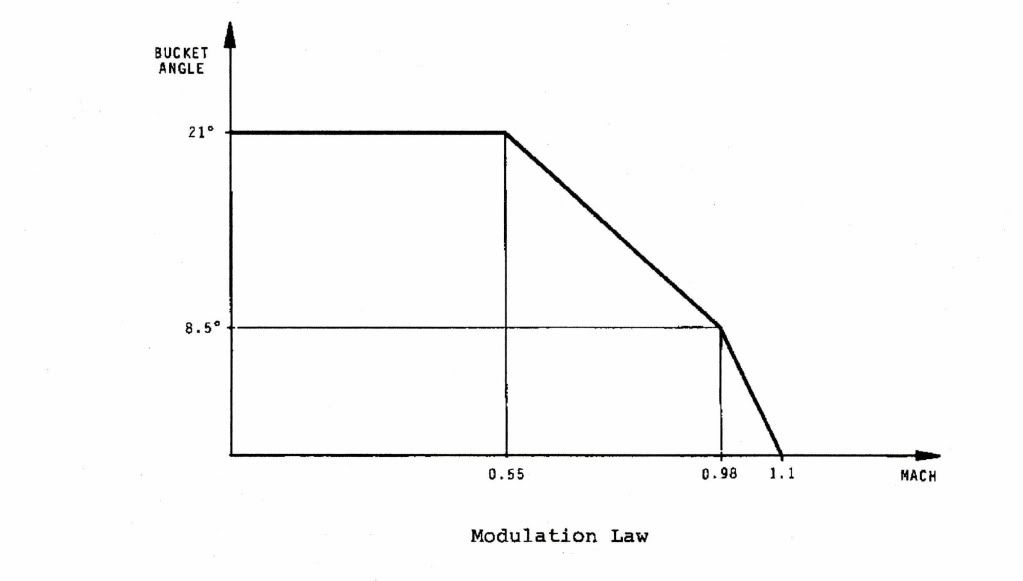
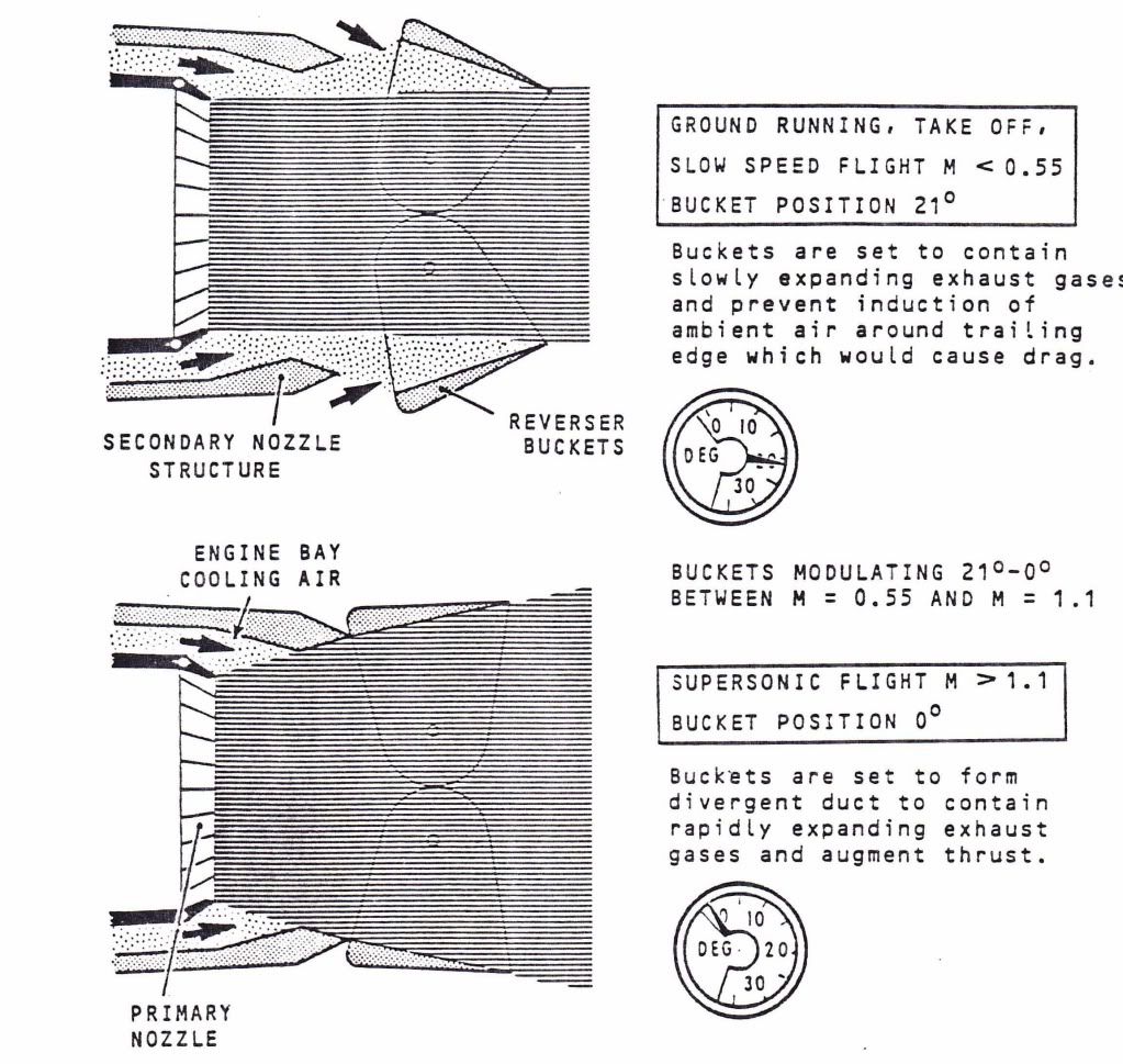
The variable secondary nozzle (wide open above Mach 1.1) allowed the jet efflux to gently expand against a cushion of air that was passed over the rear ramp of the intake, through the engine bay and into the annulus of the nozzle itself. This prevented thrust being wasted by the jet efflux widely splaying as it met ambient air that was at a pressure of as little as 1.04 PSIA.
It was this integrated powerplant that made true supersonic cruise possible
 ). There was a design flaw here in that the structure had not been designed fail-safe (allegedly by designed a Korean designer at A\xe9rospatiale who, it was said, went a bit loopy). When the FAA evaluated the design (in order for the aircraft to be registered in the USA, for Braniff operations out of IAD) they wanted 'crown planking' to be fitted externally, which would have added over a tonne to the weight of the aircraft, as well as producing some not inconsiderable drag. Fortunately a compromise was reached and additional NDT inspections were carried out, as well as more limited structural modifications. There was a long term, cost effective solution being studied, which would have cured the problem altogether. (The changes would have been mandated, over new requirements for ageing aircraft)
Nick Thomas
Nick, the whole expansion issue was one of the biggest issues that had to be addressed. Wiring looms would 'snake' in some underfllor areas to take up expansion, but the biggest difficulty of all were the mulitudes of hydraulic lines. These required sliding expansion joints, with of course seals to prevent leakage. When a seal deteriorated YPU GOT A LEAK!! (Fluid at 4000 PSI tends torun for freedom very quickly
 ). As far as fittings go, ChristiaanJ is quite right, you tried to anchor at one end only. I seem to remember that the passenger seat rails travelled over a roller afair. Fuel lines wer less of a problem, because their relative lengths were less.
I also agree wholeheartedly with ChristiaansJ's explanation about the 'friction' thing, I never really liked those stories. As a matter of interest, 127 deg's, for Mach 2, that would be at ISA +5 (-51.5 deg's C). Any warmer than that and we could not achieve Mach 2, due to the Tmo limit of 127. I remember one year, for several weeks we had unusually high north Atlantic temperatures; these impacted both the flight time AND the fuel burn. The further away you were from Mach 2, the higher the fuel consumption. (The faster you flew, the less fuel you burnt. How's that for a paradox?).
At ISA (-56.5 deg's C) temperatures, the total temperature was at around 118 deg's C.
ChristiaanJ
I remember the 17.5 degree position on the nose; it always looked as if the aircraft was trying to eat ants to me
 . I can not recall personally anyone removing the 12.5 deg' stops for access, although this could of course have been done on your side of the 'puddle' I guess.
As far as the APU ducting issue goes (hee, hee, not often we disagree Christiaan
 ) we are just going to have to agree to disagee about this, although I accept that two 4" diameter pipes (PLUS THERMAL INSULATION) might have done it, BUT I still stand by the other points.

Stlton
Its all academic now but, just out of curiosity could this have worked on the Concorde
Subjects
APU (Auxiliary Power Unit)
Afterburner/Re-heat
Braniff
Engine surge
Expansion
Flight Envelope
Fuel Burn
Hydraulic
Intakes
N1 (revolutions)
Nozzles
TMO (Temprature Max Operating)
Temperature Shear
Links are to this post in the relevant subject page so that this post can be seen in context.
Reply to this quoting this original post. You need to be logged in. Not available on closed threads.
August 24, 2010, 09:48:00 GMT
permalink Post: 5889012
Does anyone have a tech drawing of the "sliding seals" used in the hydraulics. I have trouble visualising something that could withstand the 4,000psi pressure. Why was such a high pressure used? After all the control surfaces couldn't have required that much input to effect an authority movement. I understand it was also a special fluid that was used. Was this because of the pressure it was under or the temperature extremes?
).
As far as the hydraulic expansion joints go, I will scour around and see if I can find a diagram for you. Try and picture two titanium (or stainless) tubes, on inside the other, with a sealed chamber being formed at the join. Inside this chamber were multiple lands fitted with special viton GLT seals. They did work incredibly well, although occasionally one of the seals gave out, and things got wet, VERY WET.
As far as the 4000 PSI hydraulic system, as EXWOK quite rightly pointed out, the loading on the flying control surfaces were immense throughout the whole flight envelope. (Picture alone just the T/O from JFK RWY 31L, where the aircraft is tightly turning and the gear retracting, all at the same time). As well as the flying controls and landing gear, you also had the droop nose to consider, four variable engine intakes as well as a couple of hydraulically operated fuel pumps. Oh, and in emergencies, a hydraulically driven 40 KVA generator too. The reason that 4000 PSI was chosen was that if a large amount of hydraulic 'work' was to be done, the only way to keep the size of jacks and actuators to a reasonable size/weight was to increase the system pressure by 25% from the normal 3000 PSI. (On the A380 they've gone a step further and gone for 5000 PSI, saving them over a tonne on the weight of the aircraft).
Concorde used a special hydraulic fluid, Chevron M2V. This is a mineral based fluid, as opposed to the ester based Skydrol, used by the subsonics. The reason that we went for a different fluid was a simple one; Skydrol is rubbish at the high temperatures that Concorde operated at, no good at all in fact, so we needed something better and in M2V we found the PERFECT fluid. As an aside, unlike Skydrol, that attacks paintwork, certain rubber seals, skin, EYES etc., M2V is completely harmless, wash your hair in it. (I did, several times when we had leaks. Thinking about it, maybe THAT is why my hair is such a diminished asset

EXWOK
It's so great having another of my pilot friends diving in to this post, welcome welcome
I remember the Mech' Signalling part of the air tests, my lunch has just finished coming back up thank you.
 (for interest chaps and chapesses, with mechanical signalling, using just the conventional control runs under the floor, there was no auto-stabilisation).
The artificialfeel system worked incredibly well I thought, I always found it curious that the peak load law in the computer was at the transonic rather that the supersonic speed range. It was explained to me long ago that this was because the controls really are at their most sensitive here, but at high Mach numbers are partially 'stalled out', due to shockwave movements along the surfaces, and were therefore less effective. (For this reason I was told, the inner elevons were so critical for supersonic control, being the most effective of all elevons at high speed).
To all , I forgot to mention in my previous post regarding the engine failure in G-BOAF in 1980; I remember an FAA surveyor, who was taking a look at the carnage within the engine bay, saying that in his opinion, no other aircraft in the world could have survived the intensity of the titanium fire that ensued. Analysis showed that the fire was successfully extinguished, possibly at the first shot of the fire bottle. This was a testament to the way that the Concorde engine bay could be completely 'locked down' when the fire handle was pulled, as well as to the way that the whole engine installation was technically encased in armour plate. To put all this in context, acording to Rolls Royce a titanium fire, once it takes hold, can destroy the compressor of a jet engine in four seconds.
Dude
Subjects
Airbus
Elevons
Engine Failure
Expansion
Flight Envelope
Fuel Pumps
G-BOAF
Hydraulic
Intakes
JFK
Landing Gear
Rolls Royce
Shockwave
Tailwheel
Links are to this post in the relevant subject page so that this post can be seen in context.
Reply to this quoting this original post. You need to be logged in. Not available on closed threads.
August 25, 2010, 13:23:00 GMT
permalink Post: 5891412
Thanks
Nick
Subjects
British Airways
Expansion
Links are to this post in the relevant subject page so that this post can be seen in context.
Reply to this quoting this original post. You need to be logged in. Not available on closed threads.
August 26, 2010, 12:43:00 GMT
permalink Post: 5893615
Did the repeated expansion and contraction cycle have a detremental effect on the ulitamate life of the airframe?
I read somewhere that on the last supersonic flight of each BA Concorde, the flight engineer placed his cap into the gap between his panel and the cockpit bulkhead thus leaving it there for ever more. A nice story if true.
Once again thanks
Nick
Subjects
British Airways
Expansion
Links are to this post in the relevant subject page so that this post can be seen in context.
Reply to this quoting this original post. You need to be logged in. Not available on closed threads.
August 27, 2010, 04:59:00 GMT
permalink Post: 5895262
[QUOTE]Going back to expansion and paint. With the aircraft expanding approx 6 inches and a temp change up to 127`c, I guess a special kind of paint; able to withstand such adverse conditions; must have been used? When deciding on the paint specification was any consideration given to the overall weight of the paint?[/QUOTE
Can't remember much about paint spec's, but a lot of experimentation/trial and error was carried out with different paints until the right one was found. I remember when G-BOAD was delivered, that copiuous sheets of paint had peeled off in flight. Finally a superb polyurithane paint was found that did the trick perfectly.
And the 'hat in the gap' stories are quite true.
ChristiaanJ
This was the real beauty of the autostab' on all 3 axis; you could just safely take it all for granted. The Mach 2 engine out case was a classic, as not only would the aircraft yaw towards the dead engine but there was an adverse roll input, where the wing on the same side would LIFT due to the excess intake air for the failed automatically being 'dumped' through the now open spill door. If for any reason the aircraft HAD been under manual rather than autopilot control, then life without autostab would be rather uncomfortable to say the least. And putting further Concorde's achievements in terms of stability; the world's only previous large delta winged Mach 2 aircraft, the B58 Hustler, had the slightly awkward feature in the case of an outer engine failure at Mach 2, in that the yaw forces were sufficient to tear the fin off. This happened on more than one occasion during service life of the Hustler, but engine failure (or far more likely a deliberate precautionary shut-down) although hardly a non-event in the case of Concorde, it was routinely dealt with without drama or danger.
Dude
Subjects
Auto-pilot
Auto-stabilisation
Engine Failure
Engine Shutdown
Expansion
G-BOAD
Intakes
Links are to this post in the relevant subject page so that this post can be seen in context.
Reply to this quoting this original post. You need to be logged in. Not available on closed threads.
September 08, 2010, 08:13:00 GMT
permalink Post: 5921086
Pre-accident I think we did use different tyres than AF. I also recall that BA elected to not use retreaded tyres while AF did, but am not 100% on that.
A pivotal part of the return to service was the Michelin 'NZG' tyre. (Near-Zero-Growth).
The tyres on Conc were incredibly hard-worked, partly because of the speed and partly because they took the full weight of the a/c throughout take-off (a conventional wing is producing a fair bit of lift prior to rotate - concorde produces none of note).
A LOT of energy is stored in a heavy tyre rotating this fast, so a burst can shed debris at great velocity.
The make-up of the NZG meant that it contained the expansion caused by rotation better (so less stored energy in the carcass), and had a far more robust and damage-tolerant structure. The videos of the destructive testing compared with the original tyres is frankly amazing.
The tyre was being developed by Michelin for the A380, I believe, and the principle was adopted for new Concorde tyres. In my opinion, this was the contribution which ensured we got back in the air.
Subjects
Air France
British Airways
Expansion
Tyres
Links are to this post in the relevant subject page so that this post can be seen in context.
Reply to this quoting this original post. You need to be logged in. Not available on closed threads.
September 21, 2010, 18:06:00 GMT
permalink Post: 5948141
The ctrl surfaces are made of a honeycomb-core bonded to the skins, essentially. They originally had a blunt trailing-edge, as was then de-rigeur with supersonic design. At some stage it was decided that a sharp trailing edge was actually beneficial so they had an extension fitted, which had the unfortunate effect of allowing a certain amount of water ingress to the core. Heating and expansion of this lead to disbonding and ultimately failure of the surfaces. (I suspect my engineering colleagues will have a much better and more accurate explanation).
Now - here's the important bit, and another example of this aeroplane's excellent failsafe engineering; Concorde had two rudders, one above the other (same as the 747). Each is driven by one dual-bodied PFCU. You ABSOLUTELY don't want a PFCU endangered by ctrl surface damage so each surface is divided in two, either side of the PFCU control horn.
Visualise the PFCU attached to the centre of two surfaces with an end rib on each, but skinned to look like one surface. Therefore, in the case of the surface suffering damage, it can only spread to a point short of the all-important PFCU. Look at the rudder-failure pictures and you'll see what I mean.
So - far from the 'rudder' breaking up, the reality is that half of one of the rudders had failed.
It was somewhat inevitable that Concorde's control sfcs would suffer, given the horrific loads they endured, and this was dealt with at the design stage. The elevons had the same sort of design.
It does of course look bad when you land with bits missing and this, plus the Regulators and company safety depts ensured that eventually some HUGELY expensive replacements were built.
Subjects
Boeing 747
Elevons
Expansion
PFCU (Powered Flying Control Units)
Rudder
Links are to this post in the relevant subject page so that this post can be seen in context.
Reply to this quoting this original post. You need to be logged in. Not available on closed threads.
September 25, 2010, 17:05:00 GMT
permalink Post: 5955833
Early on there was a discussion of sliding hydraulic seals (necessary to allow for thermal expansion of the airplane). It occurred to me that sliding hydraulic seals are nearly as rare as hydraulic cylinders. But that raises an obvious question: what kept the seals from acting like cylinders, and fully extending under pressure?
And then a very picky observation on the discussion about excess moisture evaporating vs. boiling off during flight at temperatures up to 100C. Wouldn't water boil well below 100C at FL 600?
Subjects
Expansion
Hydraulic
Links are to this post in the relevant subject page so that this post can be seen in context.
Reply to this quoting this original post. You need to be logged in. Not available on closed threads.
September 25, 2010, 22:03:00 GMT
permalink Post: 5956169
You're quite right, actually, especially assuming no flow.
"how would the fluid in the "cylinder" "know" it's pressing against pressurized hydraulic fluid in the inner tube and not a solid steel piston? "
The fluid wouldn't "know".. It would be pressing against pressurized hydraulic fluid further down the line.... but at the end, it would finally be pressing against the piston of a hydraulic cylinder of some kind at the end, like the 'cap' in my first scribble.
If nothing was restrained "downstream", indeed everything would be "blown apart".
Of course, that hydraulic cylinder (my 'cap') would be affixed to the structure, so it wouldn't move.
The problem is more like my second scribble.... with a bend in the pipe, and only the final 'cap' fixed, the pipe would continuously flex under pressure.... not a good idea at all, especially when the pressure in the pipe varies, because the 'cap' is not a real 'cap' but something like a PFCU (power flight control unit), with continously varying demand.
So yes, the hydraulic lines are restrained in all the right places, for the hydraulic expansion seals to work correctly without setting up stresses in the lines themselves (except for the pressure acting outwards, of course).
Hope this makes sense to you?
CJ
Subjects
Expansion
Hydraulic
PFCU (Powered Flying Control Units)
Links are to this post in the relevant subject page so that this post can be seen in context.
Reply to this quoting this original post. You need to be logged in. Not available on closed threads.
September 26, 2010, 06:19:00 GMT
permalink Post: 5956478
Dude
Subjects
Expansion
Hydraulic
Links are to this post in the relevant subject page so that this post can be seen in context.
Reply to this quoting this original post. You need to be logged in. Not available on closed threads.
October 07, 2010, 13:57:00 GMT
permalink Post: 5979844
I presume that the fuel penalty for a locked secondary nozzle was due to the reduced expansion of exhaust gas without the maximum divergent shape?
Subjects
Expansion
Nozzles
Links are to this post in the relevant subject page so that this post can be seen in context.
Reply to this quoting this original post. You need to be logged in. Not available on closed threads.
October 08, 2010, 09:06:00 GMT
permalink Post: 5981420
Now if we are locked at the 10 degree position we are at a position that will give us significant but tolerable losses throughout the flight envelope.
Subjects
Expansion
Flight Envelope
Intakes
Nozzles
Thrust Reversers
Links are to this post in the relevant subject page so that this post can be seen in context.
Reply to this quoting this original post. You need to be logged in. Not available on closed threads.
December 04, 2010, 14:17:00 GMT
permalink Post: 6101902
It's been place on my site, but I have also placed it on here so as many as possible will get a chance to read it.
Steve
\x93I am sure you will receive a lot of feedback regarding the aircraft and the maintenance work that needs to be performed. In the end, however, it comes down to one key point: the owner of the aircraft, British Airways, inspected its property, and determined that while the plane was in relatively good shape, these repairs are required. As such, the maintenance and preservation work will occur. I am sure you can agree, if the maintenance and repair did not occur, the plane would only degrade further.
Reference your source\x92s comments below:
- Airbus at Filton, and its predecessor companies, have maintained aircraft for many years and have a highly trained and skilled workforce who understand aircraft and maintenance programs
- We have performed a visual inspection of the airframe each week since the aircraft arrived and latterly had become concerned over indications of corrosion (please do not refer to this as rust) such as blistering and cracking.
- The \x93holes in the fuselage\x94 were certainly not created for TV. Our job is to maintain the aircraft, not damage it. These holes are in fact the result of corrosion in some of the lower belly panels which have been further exposed as maintenance/preparation begins. The hole in the leading edge is old damage that has been temporarily and repeatedly patched continuously over the years. We are now performing a more permanent fix.
- There are 7 windows leaking in total, including one on the flight deck which must be resealed to prevent cracking. The failure to repair leaks will present a huge risk, especially during the winter period, as window glazings can crack due to the expansion of water as it freezes, and there are very few replacements available. \x93
Subjects
Airbus
Corrosion
Expansion
Filton
Links are to this post in the relevant subject page so that this post can be seen in context.
Reply to this quoting this original post. You need to be logged in. Not available on closed threads.
April 06, 2011, 23:00:00 GMT
permalink Post: 6354939
Subjects
Expansion
Intakes
Links are to this post in the relevant subject page so that this post can be seen in context.
Reply to this quoting this original post. You need to be logged in. Not available on closed threads.
November 02, 2011, 17:09:00 GMT
permalink Post: 6785772
Is this true ?
Subjects
Expansion
Links are to this post in the relevant subject page so that this post can be seen in context.
Reply to this quoting this original post. You need to be logged in. Not available on closed threads.
November 03, 2011, 00:51:00 GMT
permalink Post: 6786509
 analog electro-mechanical Air Data Computers met RVSM minima quite comfortably when trials were carried out, and that amazed the hell out of most of us. (But a Penny & Giles DADC was still being looked at in the early to mid 90s as a potential ADC replacement).
As far as the expansion joint question goes John, there were several expansion joints all over the aeroplane but I don't recall personally being able to see evidence of thermal expansion anywhere else than the aft flight engineers panel. Perhaps someone else here may know something?.
Best regards
Dude
Subjects
ADC (Air Data Computer)
Expansion
Links are to this post in the relevant subject page so that this post can be seen in context.
Reply to this quoting this original post. You need to be logged in. Not available on closed threads.