October 22, 2010, 09:26:00 GMT
permalink Post: 6010620

 , we have: London LHR (duhhh!!), Bahrein BAH, Singapore SIN, New York JFK, Washington IAD, Dallas DFW, Miami MIA, Toronto YYZ, Barbados BGI, and Riyadh RUH. As well as charters being ommited, so are some of the special 'surprise' shuttle appearances that Concorde would make, substituting a subsonic to and from destinations such as Manchester and Edinburgh.
 ).
).
Landing - 27L & R, 9L & R (prior to LHR mag' deviation update were 28L & R & 10L & R) together with 23/05.
Take off - 27L (28L), 9R (10R) and 9L. (10L never happened as take offs on this runway only occurred in 2003).

I hope you guys had fun with this one, regards to all
Dude

Last edited by M2dude; 22nd October 2010 at 11:21 . Reason: oops, misssed out question 2
Subjects
Afterburner/Re-heat
Air France 4590
Auto-stabilisation
Barbados
Braking
British Airways
Brize Norton
Fairford
Fatigue
Filton
Flight Envelope
Fuel Burn
Fuel Pumps
G-AXDN
INS (Inertial Navigation System)
Intakes
JFK
LHR
LHR Operations
LHR-JFK Route
Landing Gear
N1 (revolutions)
Nozzles
Quiz
RAE Farnborough
Relight
Shannon
Thrust Reversers
Toulouse
Trim
Links are to this post in the relevant subject page so that this post can be seen in context.
Reply to this quoting this original post. You need to be logged in. Not available on closed threads.
October 24, 2010, 22:18:00 GMT
permalink Post: 6015446

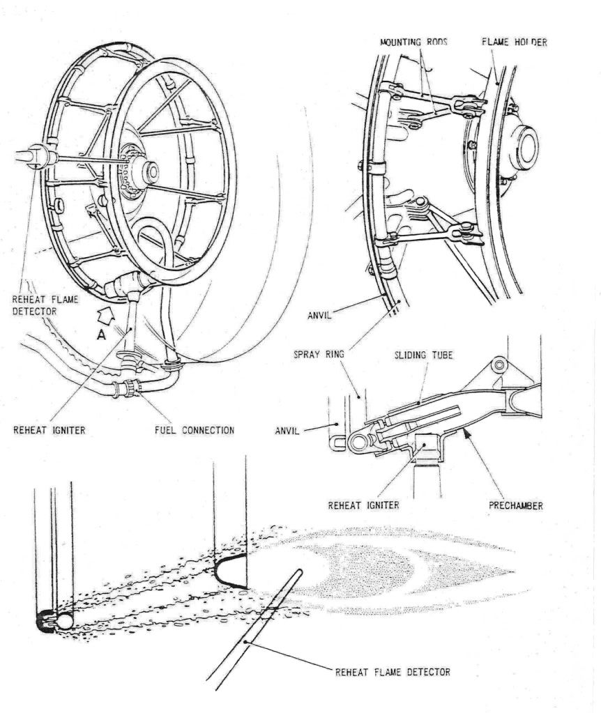
As promised, here are a few diagrams of the Concorde reheat (afterburner, for our American friends) system. The ORIGINAL design was done by SNECMA, but due to them getting into all sorts of trouble with the fuel injection system and flame stabilisation, Rolls Royce baled them out, and it became a Rolls Royce/SNECMA design. (The core engine was a 100% Rolls design, with no French input whatsoever. However some engine sub-assembles were manufactured by SNECMA).
The basic way the afterburner worked was by spraying the fuel FORWARDS intially at high pressure, against the jet stram about one inch, until it hit the anvil. . As the fuel strikes the anvil it is blown back by the jet stram and atomises, passing over the of the spray ring and the over the flame holder. The ignition operated by passing 15KV across a dual cylindrical tube, the resulting arc was 'swirlied' into the fuel stream by blowing engine 5th stage HP compressor air into the tube (there were 7 stages in all).
The key to successful ignition was a healthy spark, a good supply of air to the ignitor and accurate scheduling of fuel flow. (This was scheduled against dry engine flow as a funtion of total temperature). The other important factor (as with any afterburner) was correct and rapid operation of the exhaust nozzle. Fortunately, Concorde used it's primary nozzle for control of engine N1 anyway, so adapting this to operate as an afterburning nozzle also was a relative walk in the park, and it operated superbly.
During the light up phase of 3.5 seconds, the fuel ratio is a fixed 0.45 (ie. reheat fuel is 45% of dry fuel). After the light up phase the full scheduling commenced. As far as the FLIGHT RATING figures go (not take-off) the ratios were 0.6 at a TAT of 54 deg's C, falling linearly to 0.3 at 107 deg's C and above. (Remember that Concorde used afterburning really sparingly, just for take-off and then transonic acceleration; cut off at Mach 1.7 altogether.

Dude
Subjects
Afterburner/Re-heat
Fuel Burn
HP Compressor
Ignitors
N1 (revolutions)
Nozzles
Rolls Royce
TAT (Total Air Temperature)
Transonic Acceleration
Links are to this post in the relevant subject page so that this post can be seen in context.
Reply to this quoting this original post. You need to be logged in. Not available on closed threads.
November 03, 2010, 04:28:00 GMT
permalink Post: 6035000
My best guess - at least 200% more. Probably higher.
A comparison:
Typical Concorde taxying fuel burn: 6500kgs/hr
Typical 777-200 cruising fuel burn: 6500kgs/hr
Of course, as we've already discussed earlier, the magic thing about Concorde was that once you'd got to Mach2 its efficiency was outrageously good - better miles per gallon than a 747. An option not available, however, between LHR and MAN.
Edited to add: a slow taxy out at LHR would almost definitely consume more fuel than the 737 would burn for the sector.
Subjects
Boeing 747
Fuel Burn
LHR
Links are to this post in the relevant subject page so that this post can be seen in context.
Reply to this quoting this original post. You need to be logged in. Not available on closed threads.
November 05, 2010, 11:56:00 GMT
permalink Post: 6040606
Way back in the late 1970's we did a major modification to the intakes that increased capture area by 2.5% and gave us typically a 1.6% improvement in trans-Atlantic fuel burn, and although this was our biggest performance improvement modification, there were more:
The famous elevon and rudder trailing edge extension modifications (that due to poor design, produced in later life the water ingress induced honeycomb failures) together with the re-profiled fin leading edge modification, I never saw the performance gains quantified (anyone have any ideas?).
Can anyone here remember the riblet trial? In the mid 1990's Airbus supplied 'stick on' plastic riblets, applied to various areas on the under-side of the wing on G-BOAG. These riblets had very fine undulations moulded into the surface; the idea being that as the air flowed through and around the riblet patches, boundary layer turbulence, and hence induced drag would be reduced. Now, the performance gains (if any) were never quantified, mainly because the riblet patches either peeled off or the surface deteriorated with the continuous thermal cycle. (I was over in JFK when the aircraft first arrived after having the riblets fitted, and as the crew were trying to proudly show me these amazing aerodynamic devices, they were sadly embarassed, as several had dissapeared in the course of a single flight).

There was one modification, proposed by Rolls Royce in the late 1990's that did have quite a lot of potential; this was to increase the engine N1 by around 1.5%. This would have had the effect of increasing engine mass flow and therefore reducing the drag inducing spill of supersonic air over the lower lip of the intake. Depending on the temperature, the performance gains were in the order of a 1.5% improvement in fuel burn at ISA Plus upper atmosphere temperatures ('normal' LHR-JFK) to none at all at significant ISA Minus temperatures (LHR -BGI). The modifacation had been trialed on G-BBDG before her retirement in the early eighties, and was proven in terms of performance enhancement and engine stability. In order to keep TET at the pre-modification level, there was a small increase in N2 commanded also. (The higher N1 required an increase in primary nozzle area, reducing TET). The main reason for the modification not being implemented was one of cost; The Ultra Electronics Engine Control Units were analog units, and the modification was a simple replacement of two resistors per unit. However because ultimate mass flow limitation was also controll by the digital AICU (built by British Aerospace Guided Weapons Division) the cost of getting a software update for this exremely 'mature' unit was found to be prohibitive.
A certain 'brainy' SEO and myself were working on a modification to improve fuel burn on ISA minus sectors. The idea was to force the autopilot, in Max Cruise at low temperatures only , to fly the aircraft close to Mmo, rather than at Max Cruise speed of Mach 2 - 2.02; this would have given us gains of up to 1%, depending on the temperature. The basic electronics involved for the modification were relatively straightforward, but it was never pursued due to the complexity of dealing with temperature shears and the cost of certification.
Dude
Last edited by M2dude; 5th November 2010 at 15:49 .
Subjects
AICU (Air Intake Control Computer)
Airbus
Auto-pilot
Elevons
Fuel Burn
G-BBDG
G-BOAG
Intakes
JFK
LHR
LHR-JFK Route
Mmo
N1 (revolutions)
Nozzles
Rolls Royce
Rudder
Temperature Shear
Links are to this post in the relevant subject page so that this post can be seen in context.
Reply to this quoting this original post. You need to be logged in. Not available on closed threads.
November 18, 2010, 12:25:00 GMT
permalink Post: 6069344
The use of E LOW above 220KIAS was not only strictly inhibited by the automatics, if you over-rode the automatics and 'hard selected' E LOW , the aircraft would fall out of the sky when reheat was cancelled at Mach 1.7. This was because the low N1/√θ scheduled by E LOW would now invoke an N2/√θ limit (The E3 Limiter in the diagram) and claw off fuel flow by the tonne.
The most efficient schedule for supersonic cruise was E HI which again would be automatically selected.
E-MID was automatically selected during afterburning operation, to minimise the chance of an N1 overspeed on cancellation of reheat. E-MID could also be selected by the E/O for noise abatement approach.
E Flyover was as we discussed before used for take-off flyover noise abatement as well as subsonic cruise if desired. (If Mach 1 was exceeded with E Flyover still selected, a yellow NOZZLE light illuminated and E HI would be automatically selected.
I sincerely hope that this blurb is not clear as mud, feel free to ask away.
=> higher Fuelflow require to keep N2 run at constant speed]
).
Regards
Dude

Last edited by M2dude; 18th November 2010 at 15:04 . Reason: I goofed.. (another sign of age)
Subjects
Afterburner/Re-heat
British Airways
Fuel Burn
LP Turbine
N1 (revolutions)
Noise Abatement
Nozzles
Rolls Royce
Vortex
Links are to this post in the relevant subject page so that this post can be seen in context.
Reply to this quoting this original post. You need to be logged in. Not available on closed threads.
November 19, 2010, 22:00:00 GMT
permalink Post: 6072895
best config shape [lest sat suitable] that provide a con-di nozzle for
maximize thrust. [Not open to wide that exhaust can't reach M1 at the
throat of Prim nozzle].
Feathers McGraw

Best regards
Dude
Last edited by M2dude; 20th November 2010 at 05:10 .
Subjects
Afterburner/Re-heat
British Airways
Flameout
Fuel Burn
N1 (revolutions)
Nozzles
Thrust Reversers
Vortex
Links are to this post in the relevant subject page so that this post can be seen in context.
Reply to this quoting this original post. You need to be logged in. Not available on closed threads.
November 30, 2010, 10:16:00 GMT
permalink Post: 6092495
 ). She would also require pre-flight chemical anti-icing/de-icing treatment from a ground truck just like the rest, in shall we say, 'less than tropical conditions'. (Winters in Prestwick during crew base training... such fond memories
 ). As far as active ice protection on the wings, there was a highly sophisticated Lucas electrical 'spraymat' system fitted, but only the wetted areas of the wing, forward of the engines were 'covered'. Two digitall cyclic timers (CTPUs) would automatically regulate cyclic switching on and off of 115 VAC for various load areas of the wing at a time at pilot pre-selectable intervals (2, 4 or 8 seconds). Also as part of this system, there was
continuous
de-icing for certain other load areas too, so you had a mix of cyclic and continuous de-icing in operation. The whole idea here was to prevent chunks of ice entering and damaging the engines, the only other areas of this electrical de-icing system were the intake lips and side-walls and also the D Box area above the auxilliary inlet vane, built into the spill door. (This would only operate if the auxilliary inlet door itself was open). The whole shooting match would automatically switch itself off, for obvious reasons, above a TAT of 15\xb0 C. (ie. the vast majority of the flight). The only other de-icing system (apart from the galley drain masts) was on the engine inlet guide vanes, but this was purely pneumatic and again would swith itself off above 15\xb0 C.
). As far as active ice protection on the wings, there was a highly sophisticated Lucas electrical 'spraymat' system fitted, but only the wetted areas of the wing, forward of the engines were 'covered'. Two digitall cyclic timers (CTPUs) would automatically regulate cyclic switching on and off of 115 VAC for various load areas of the wing at a time at pilot pre-selectable intervals (2, 4 or 8 seconds). Also as part of this system, there was
continuous
de-icing for certain other load areas too, so you had a mix of cyclic and continuous de-icing in operation. The whole idea here was to prevent chunks of ice entering and damaging the engines, the only other areas of this electrical de-icing system were the intake lips and side-walls and also the D Box area above the auxilliary inlet vane, built into the spill door. (This would only operate if the auxilliary inlet door itself was open). The whole shooting match would automatically switch itself off, for obvious reasons, above a TAT of 15\xb0 C. (ie. the vast majority of the flight). The only other de-icing system (apart from the galley drain masts) was on the engine inlet guide vanes, but this was purely pneumatic and again would swith itself off above 15\xb0 C.
I think you will find that precious little of Concorde is now not generally available in the public domain, some control software and laws are still I would expect covered by some sort of patent. (That is why when I publiished here the engine 'E Schedule' graphs I deliberately deleted the equations for the various running lines.
Your efficiency question was a valid one; as IAS and Mach number increase the aerodynamic drag (in all it's forms) will generally increase, but the efficiency OF A WELL DESIGNED powerplant wil also increase, and Concorde was definately no exception here. The real beauty of Concorde was just HOW MUCH the powerplant efficiency increased with increasing speed and more than totally eclipsed the aerodynamic drag rise with this increasing speed. At supersonic speeds, the closer you could fly to Vmo/Mmo the lower the fuel burn was. (Especiall true at Mach 2, although the autopilot would hold you Mach 2 (ish) in Max Cruise mode, flying closer to Mmo, Mach 2.04, would save fuel, assuming the static air temoerature was low enough to sustain this). This fact (along with about a million others) produced what we all like to call 'The Magic of Concorde'

Best Regards
Dude
Last edited by M2dude; 30th November 2010 at 12:21 .
Subjects
Auto-pilot
Fuel Burn
Galley
IAS (Indicated Air Speed)
Intakes
Mmo
TAT (Total Air Temperature)
Links are to this post in the relevant subject page so that this post can be seen in context.
Reply to this quoting this original post. You need to be logged in. Not available on closed threads.
December 03, 2010, 12:19:00 GMT
permalink Post: 6099643
The whole idea of adapting hotstreak injection came from our Rolls-Royce rep', who spent many years on RB199 development. We'd even identified the position on the Olympus 593 for the injector itself; un unused start atomiser port, but as I reluctantly said before, it was not to be.
Apart from ignition issues the other main problems were reheat instability and reheat 'coming in with a thump', this particular malady being generally confined to transonic acceleration and not take-off.
The instability issue was caused by either an open circuit/high resistance fuel metering valve tacho (only rate feedback was used here) or more commonly contamination of the RFCU umbilical electrical connector. The connector itself was originally located high up the side of the engine, close to the combustion area, was barely accessable and was a total nightmare in terms of reliability. After a great deal of pressure from us (BA) SNECMA agreed to effectively relocate the connector at the bottom of the engine and the majority of our stability problems almost disapperared overnight.
The 'reheat in with a thump issue was a real beaut'. For transonic acceleration a much lower ratio of Fr/Fe (reheat fuel flow/engine fuel flow) was used than for take-off. (0.45 as opposed to 0.78) and therefore the opening rate of the fuel metering valve required damping, this being achieved by using a metered orifice inside the RFCU that applied a small amount of servo fuel pressure to one side of the valve to achieve the damping. Trouble was, any contaminants in the reheat fuel system would progressively clog up the orifice and kill our daming stone dead; the end result being the FMV banging wide open and hence the 'thump'. The only remedy for this problem was to replace the RFCU. SNECMA, in a truly classic feat of engineering produced a filter across this orifice, in order to prevent it getting clogged. Anyone see a problem with this? Yep, the filter itself would clog up and we got our beloved thump back.
 The only remedy for this problem was again to replace the
 RFCU. The contaminants were often as a result of RFCU build issues; this issue was never truly resolved.
I checked and found the dodgy sustained N1 band for the Olympus 593, this was 88-91% N1. This figure was never an issue in service as at cruise ISA -7 and above conditions the N1 was always run at the flat rate limit of 101.5%. Below ISA -7 the intake system would progressively reduce N1 as a function of intake local Mach Number, falling to 97.4% at ISA -24. (The coldest cruise conditions I personally ever saw was ISA - 25 (that's -81.5 degrees C folks) between BAH and BKK.
The controlled N1 at all other 'non cruise' phases was always in the upper 90's, well away from our blade resonance area.
jodeliste and Alpine Flyer
Thank you both for the TSR-2 information, it makes amazing reading (what a truly magnificent aircraft) , and as Concorde's military cousin, discussion here is in my opinion most waranted.
Regards
Dude
Subjects
Afterburner/Re-heat
British Airways
Fuel Burn
Intakes
N1 (revolutions)
Olympus 593
Rolls Royce
Transonic Acceleration
Links are to this post in the relevant subject page so that this post can be seen in context.
Reply to this quoting this original post. You need to be logged in. Not available on closed threads.
December 18, 2010, 15:20:00 GMT
permalink Post: 6129540
Speedbird 2, cleared take-off 31L.
You call 3-2-1 Now , start your stopwatch, pre-set to countdown from 58 seconds, and slam the throttles fully forward till they hit the stops. Four RR Olympus engines start to spool up to full power and four reheats kick in, together producing 156,000 lbs of thrust, but at a total fuel flow of 27,000 US gallons per hour. A touch of left rudder initially to keep straight, as the #4 engine limiter is limiting the engine to 88% until 60 kts when it will release it to full power. The F/O calls Airspeed building, 100 kts, V 1 , and then, at 195 kts, Rotate . You smoothly rotate the aircraft, lift-off occurs at around 10\xb0 and 215 kts. You hear a call of V 2 but you keep rotating to 13.5\xb0 and then hold that attitude, letting the aircraft accelerate.
The F/O calls Positive Climb and you call for the Gear Up . On passing 20 feet radio height, and having checked the aircraft attitude, airspeed and rate of climb are all satisfactory, the F/O calls Turn and you slowly and smoothly roll on 25\xb0 left bank to commence the turn out over Jamaica bay. Some knowledgeable passengers will have requested window seats on the left side of the aircraft at check-in, and are now being rewarded with a very close look at the waters of Jamaica Bay going by very fast! As you accelerate through 240 kts, the F/O calls 240 and you pitch up to 19\xb0 to maintain 250 kts and keep the left turn going to pass East of CRI.
54 seconds from the start of the take off roll you hear the F/O counting down 3-2-1 Noise whereupon the F/E cancel the re-heats and simultaneously throttles back to noise abatement power, around 96% as you pitch the nose down to 12\xb0 to maintain 250 kts. It is less than a minute from start of roll and already 435 US gallons of fuel have been used.
Speedbird 2, contact departure, so long.
Turning through heading 235\xb0M, the F/E quickly re-applies full dry power as you pitch up to 17\xb0 to maintain 250 kts, but simultaneously reduce the left bank to 7.5\xb0, in order to increase both the radius of turn (to stay on the optimum noise abatement track) and the rate of climb (less bank, higher RoC).
On climbing through 2,500 ft you increase the bank angle back to 25\xb0 left bank and as you approach the 253\xb0 radial JFK, you hear 3-2-1 Noise from the F/O for the second time. The F/E actions the second noise-abatement power cut back, you pitch down to 12\xb0 and, if not in cloud, sneak a quick peek out of your left hand window, looking for the car park by the Marine Parkway bridge, as you would ideally like to pass right over the car park, if possible, as we tip-toe quietly across the Rockaway Beaches, in order to minimise the noise impact on the residents.
Keep the left turn going and intercept the 176\xb0 radial outbound from CRI, and at 5 miles DME from CRI, call for the F/E to slowly re-apply full climb power as you pitch up to maintain 250 kts. We are still in US territorial airspace, below 10,000 ft, and subject to statutory speed control.
Speedbird 2, present position direct to SHIPP, climb FL230, no speed control.
The F/O selects direct SHIPP in the INS and tells you that she has selected that information into your Flight Director. Having checked that the gear lever is at neutral, you call for the Nose Up , and then the Visor Up . Flight deck noise levels drop dramatically as the Visor locks up. Now more than 12 miles away from the coast, we are clear of US speed control requirements so lower the attitude to 9\xb0, accelerate to V MO , currently 400 kts, and ask for the After Take Off Checks.
Speedbird 2, present position direct to LINND, climb in the block FL550-600, accelerate Mach 2.0
Call for the Climb Checklist at Mach 0.7, which will trigger the F/E to start pumping fuel rearwards to move the CG aft, then when he's done that, straight into the Transonic Checklist . Maintain 400 kts IAS, and around 24,500 ft, at M0.93, ask for the re-heats back on, in pairs, and raise the nose by 3\xb0 to maintain 400 kts as they kick in.
Precise, smooth flying is required through the high drag transonic region, as the mach meter creeps up towards Mach 1. A sudden flicker on the VSI and Altimeter confirms that the shock wave has just passed over the static ports, and the aircraft is now supersonic. A quick glance at the elapsed time indicator shows that you\x92ve been hand flying for just over 9 minutes since the start of the take off roll.
Another fun start to a day in the office, and to think we got paid for doing it!
Best Regards
Bellerophon
Subjects
Afterburner/Re-heat
C of G
Checklists
Fuel Burn
Hand Flying
IAS (Indicated Air Speed)
INS (Inertial Navigation System)
JFK
Noise Abatement
Rolls Royce
Rudder
Static Ports
V1
V2
Visor
Links are to this post in the relevant subject page so that this post can be seen in context.
Reply to this quoting this original post. You need to be logged in. Not available on closed threads.
December 23, 2010, 00:39:00 GMT
permalink Post: 6138601
Digging out the old BAe conversion course notes:
The "Anti-Stall" (SFC) 1&2 sytems offered:
Super Stab: Increased authority of pitch autostab as incidence increased above 13.5 degrees - proportional to pitch rate and incidence angle - and a nose down pitch trim with a Vc (CAS) deceleration with incidence > 13.5
Stick "Wobbler": the "unmistakable warning" - when incidence > 19 and Vc<270kts the control columns took a life of their own and tried to fling you into the forward galley. Served you right.
Some other high incidence stuff was fed from the ADC rather than the SFC, like:
The ">13.5d incidence" feed to the SFC
CAS (Vc) feed to the SFC
Incidence from 16 to 19 degrees (rate dependant) to get the SFC to feed in up to 4 degree nose down pitch command and the sticj wobbler trigger.
Increase of authority of yaw autostab as incidence > 13.5d
Autotrim inhibit > 14.5d incidence
Stick shaker >16.5d incidence
AP/FD disconnect > 17.5d incidence
There was loads of other technical stuff which engineers understood, but we had to learn by writing diagrams which made sense to us enough to pass the written exam. The bottom line was an aeroplane which flew beautifully, but which you had to understand well, and which you could not tease beyond its limits. If you ignored a limit or an SOP then you reached an unpleasant place far quicker than with the blunties - it was a challenge which rewarded as quickly and as deeply as it punished.
Subjects
ADC (Air Data Computer)
Auto-stabilisation
Auto-trim
Conversion Course
Fuel Burn
Galley
Stick Shaker
Trim
Links are to this post in the relevant subject page so that this post can be seen in context.
Reply to this quoting this original post. You need to be logged in. Not available on closed threads.
December 23, 2010, 08:31:00 GMT
permalink Post: 6138954
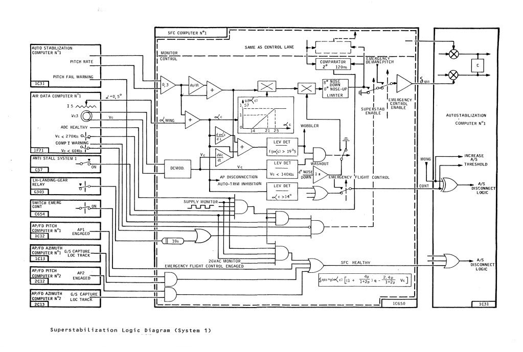
To hopefully further clarify, this was controlled from the SFC computer and was a two part mix:
1) With Vc < 270 KTS the AUTOSTAB pitch damping was increased as a function of pitch rate and pitch rate DOT, Vc DOT and corrected (wing) incidence. Maximum possible demand limited to 8\xb0 nose down.
2) With Vc < 140 KTS and alpha/alpha rate greater than 19.5\xb0 (this itself would generate the 'wobbler' or 'unmistakable warning') a 4\xb0 nose down signal is generated over a 1 second time constant.
I hope the enclosed diagram helps to put it all in place.
Best Regards
Dude
Subjects
Auto-stabilisation
Fuel Burn
Links are to this post in the relevant subject page so that this post can be seen in context.
Reply to this quoting this original post. You need to be logged in. Not available on closed threads.
December 23, 2010, 08:56:00 GMT
permalink Post: 6139004
Subjects
Fuel Burn
Links are to this post in the relevant subject page so that this post can be seen in context.
Reply to this quoting this original post. You need to be logged in. Not available on closed threads.
December 24, 2010, 21:35:00 GMT
permalink Post: 6142030
In my case, it's easier... I've become bitten by the Concorde bug again over the last ten years or so, and pulled dozens of similar diagrams from the documentation to refresh my memory.
Op-amps also were used for other functions such as demodulators (converting AC signals to DC) or comparators and level detectors.
I still mean to write some posts on "how to compute without a digital computer", but it'll have to wait until after the holidays.
In the 'olden' days we'd draw block diagrams like the one for the SFC, and once we agreed about all the functions we wanted, we just drew the schematics for each of the functions.
No sequencing, no real-time clock, no A/D or D/A conversion, no worries about cycle time or memory allocation. No programming-language issues, no naming of variables, no compiler faults, no software to debug.
You should try it sometime......
The major issue was, of course, that you ended up with a lot more hardware for the same functionalities, hence more weight, and more power consumption.
And the other issue, already alluded to in earlier posts, is that analogue computing is inherently not highly accurate.
In many cases of system control, a percent or two of precision is perfectly acceptable. But if a far higher precision is needed, like for instance in the intertial navigation system, or the core computing for the air intakes, only digital computing can do the job.
Seasons greetings to everyone on this thread from me too.
Christian
Subjects
Fuel Burn
Intakes
Links are to this post in the relevant subject page so that this post can be seen in context.
Reply to this quoting this original post. You need to be logged in. Not available on closed threads.
December 28, 2010, 21:54:00 GMT
permalink Post: 6147254
My guess is that the upper digital counter indicates the proportion of the fuel flow that goes to the reheat but it's only a guess.
Sorry, I have no figure for the max fuel consumption.
The '35 tonnes/hr' limit on the indicator is obviously beyond the upper limit, like the speedo on a car.....
But yes, fuel consumption at takeoff with reheat was horrendous, and would have emptied all the tanks in an hour or less.
CJ
Subjects
Afterburner/Re-heat
Fuel Burn
Haynes guide to Concorde
Links are to this post in the relevant subject page so that this post can be seen in context.
Reply to this quoting this original post. You need to be logged in. Not available on closed threads.
December 29, 2010, 03:57:00 GMT
permalink Post: 6147577
...I have been a Concorde fan since I won a flight on it in 1980...
Lucky devil! I'm glad you enjoyed the flight.
...There appears to be two digital displays per gauge as well as an analogue display...
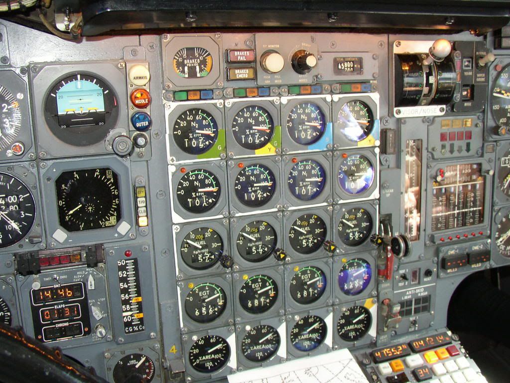
Only the lower digital counter was actually a display, and was a digital repeater of the total fuel flow information being displayed by the pointer on the dial. The upper digital counter was merely a digital indication of the value to which the internal yellow triangular bug had been set by the F/E using the bug setting knob on the lower right of the gauge.
Very briefly, during the pre-flight set up, the F/E would calculated the expected fuel flows for each engine, during the take-off whilst using re-heats. He would set this on the bug, and this achieved two things.
Firstly, it gave him a good visual indication whether the required fuel flows were being achieved. Too low a fuel flow would indicate a re-heat problem on that engine.
Secondly, it programmed the expected fuel flow into the engine take-off monitor, as this was one of the parameters that had to be satisfied in order for the monitor to illuminate the Green \x93Clear-to-Go\x94 light.
The Green \x93Clear-to-Go\x94 light was one of three \x93Power Management\x94 lights immediately above the N2 gauge for each engine, the other two being an Amber \x93Configuration\x94 light and a Blue \x93Reverse\x94 light. Some take-offs would require all four Green lights to be on, other take-offs, depending on ambient conditions, aircraft weight and runway length, might only require three Green lights.
...What was the peak consumption per engine, and why two digital displays on each gauge?...
The maximum peak consumption predicted was 21,700 kg/eng/hr, or 86,800 kg/hr total. This would have been predicted for a re-heated take-off, at +8\xb0C, at an elevation of -1,000 PA.
More typically, on a standard day, at a sea level airfield, 20,700 kg/eng/hr, or 82,800 kg/hr total. You can probably see why we turned the re-heats off fairly quickly!
...accelerating to Mach 2.0 and immediately slowing down again....we only went to 43,000 feet so the sky did not get very dark...
43,000 ft is actually a bit too low for Concorde to be at M2.0, as you may see from this graph of her Flight Envelope. She would have been limited to around 525 kts / M1.7 at that height, so I suspect you may have been a little higher than you remember, possibly somewhere around 53,000 ft.
Happy New Year
Bellerophon
Subjects
Afterburner/Re-heat
Flight Envelope
Fuel Burn
Links are to this post in the relevant subject page so that this post can be seen in context.
Reply to this quoting this original post. You need to be logged in. Not available on closed threads.
December 29, 2010, 11:21:00 GMT
permalink Post: 6148025
Gentle descent in the crz, N1 max, N2 max, similar fuel burn per engine as a 747 (but over double the speed), Airspeed and Mach numbers just shy of the barber's poles, must have been well above FL500 given the Mach number yet the cabin alt is a smidge over 5000'.
Elapsed time 1hr 31, Longitude over 41W. Took me over three hours to get to 40W yesterday.......
PS and it has to be OAD, because for some reason the nose/visor control panel is black. I've no idea why I can remember stuff like that, but not the name of someone I met last week......
Subjects
Boeing 747
Fuel Burn
N1 (revolutions)
Links are to this post in the relevant subject page so that this post can be seen in context.
Reply to this quoting this original post. You need to be logged in. Not available on closed threads.
December 29, 2010, 11:28:00 GMT
permalink Post: 6148035
Subjects
Afterburner/Re-heat
Fuel Burn
Links are to this post in the relevant subject page so that this post can be seen in context.
Reply to this quoting this original post. You need to be logged in. Not available on closed threads.
December 29, 2010, 13:53:00 GMT
permalink Post: 6148266
Subjects
Boeing 747
Fuel Burn
Links are to this post in the relevant subject page so that this post can be seen in context.
Reply to this quoting this original post. You need to be logged in. Not available on closed threads.
April 03, 2011, 21:16:00 GMT
permalink Post: 6348525
The F/O calls Positive Climb and you call for the Gear Up . On passing 20 feet radio height, and having checked the aircraft attitude, airspeed and rate of climb are all satisfactory, the F/O calls Turn and you slowly and smoothly roll on 25\xb0 left bank to commence the turn out over Jamaica bay. Some knowledgeable passengers will have requested window seats on the left side of the aircraft at check-in, and are now being rewarded with a very close look at the waters of Jamaica Bay going by very fast! As you accelerate through 240 kts, the F/O calls 240 and you pitch up to 19\xb0 to maintain 250 kts and keep the left turn going to pass East of CRI.
Subjects
Afterburner/Re-heat
Fuel Burn
Rolls Royce
Rudder
V1
V2
Links are to this post in the relevant subject page so that this post can be seen in context.
Reply to this quoting this original post. You need to be logged in. Not available on closed threads.
April 24, 2011, 14:09:00 GMT
permalink Post: 6409591
I would have thought that the whole venture was a proof of concept by SFENA for future implementation in the Airbus family. This excersise would have been both costly and highly complex at system level, any other reason would really have been quite daft.
Best Regards
Dude
Last edited by M2dude; 24th April 2011 at 15:08 .
Subjects
Airbus
Auto-stabilisation
Elevons
Fuel Burn
Sidestick
Vmo
Links are to this post in the relevant subject page so that this post can be seen in context.
Reply to this quoting this original post. You need to be logged in. Not available on closed threads.