August 16, 2010, 16:37:00 GMT
permalink Post: 5873511
In the meantime, here's the MEPU exhaust in the tailcone of Delta Golf, courtesy of Neil Walker.
CJ
Subjects
G-BBDG
MEPU (Monogol Emergency Power Unit)
Tail Cone
Links are to this post in the relevant subject page so that this post can be seen in context.
Reply to this quoting this original post. You need to be logged in. Not available on closed threads.
August 16, 2010, 19:53:00 GMT
permalink Post: 5873899
Subjects
G-AXDN
Links are to this post in the relevant subject page so that this post can be seen in context.
Reply to this quoting this original post. You need to be logged in. Not available on closed threads.
August 21, 2010, 22:04:00 GMT
permalink Post: 5884612
Re your questions about the CofG, this diagram should help you to visualise the CofG "corridor".
It's the one for G-AXDN (01) but the production one is closely similar.
To make some more sense of this.... all those percentages quoted are in terms of the "wing root reference chord".
Mentally cut the wing off the fuselage and measure the length of the cut (including the elevons)..
That's the "root reference chord", and it's 27,76 m.
To give you another reference point: the main gear attachment point is located at 57% ""root reference chord".
So any CofG beyond 57% on the ground, and you have yourself a tailsitter (it's happened)..
Subjects
C of G
Elevons
G-AXDN
Landing Gear
Links are to this post in the relevant subject page so that this post can be seen in context.
Reply to this quoting this original post. You need to be logged in. Not available on closed threads.
August 22, 2010, 13:18:00 GMT
permalink Post: 5885515
...The altitude flown was due to temperature and weight of the areoplane. This is true of all aeroplanes...
Sadly, it isn’t, as subsonic aircraft are allocated a specific cruising flight level and often - for example on the North Atlantic Track system - a specific cruising Mach number as well, and no deviation from that clearance is permitted without specific permission from ATC. Obviously everyone flight plans at the most economic heights and speeds for their aircraft type, but in busy airspace not everyone gets what they want!
Think of your flight plan as being Angelina Jolie, and your ATC clearance as being your wife. Your flight plan is what you’d really like to have, but your ATC clearance is what you’re going to have to live with!
... altitude flown was due to temperature and weight of the areoplane...this was more true of Concorde?...
Subsonic aircraft could equally benefit from using cruise-climb techniques (early long range aircraft crews knew all about cruise-climb techniques and used them when able) but with the large number of subsonic aircraft now using the world’s airways it is impractical for ATC to allow them to drift up and down at will, and so they are assigned specific cruising altitudes.
Few other aircraft got up to Concorde’s cruising levels, and so ATC were able to issue much more flexible clearances to her.
A typical Concorde ATC clearance would have allowed her to accelerate to M2.00 whilst operating within a "block" of altitude, rather than at a specific flight level. Typically this block clearance would have been to operate anywhere between FL450 up to FL600 without restriction.
So, unlike subsonic aircraft assigned a fixed cruising altitude such as FL350, Concorde could, and did, drift up or down, and was thus able to remain at the optimum altitude for the prevailing conditions throughout most of the flight.
... I remember reading the BA Concorde flew with 2 Captain Pilots (and of course the most important Flight Engineer)...
Concorde operated, as did all 3 crew aircraft in BA, with a standard crew of a Captain, F/O and F/E.
A small number of trips had two Captains on board (or two F/Es for that matter) when training or checking was going on, or an extra crew member was carried for PR purposes, but otherwise, the vast majority of occasions, just the standard crew was on board. Everyone preferred it that way, especially the F/O and F/E!
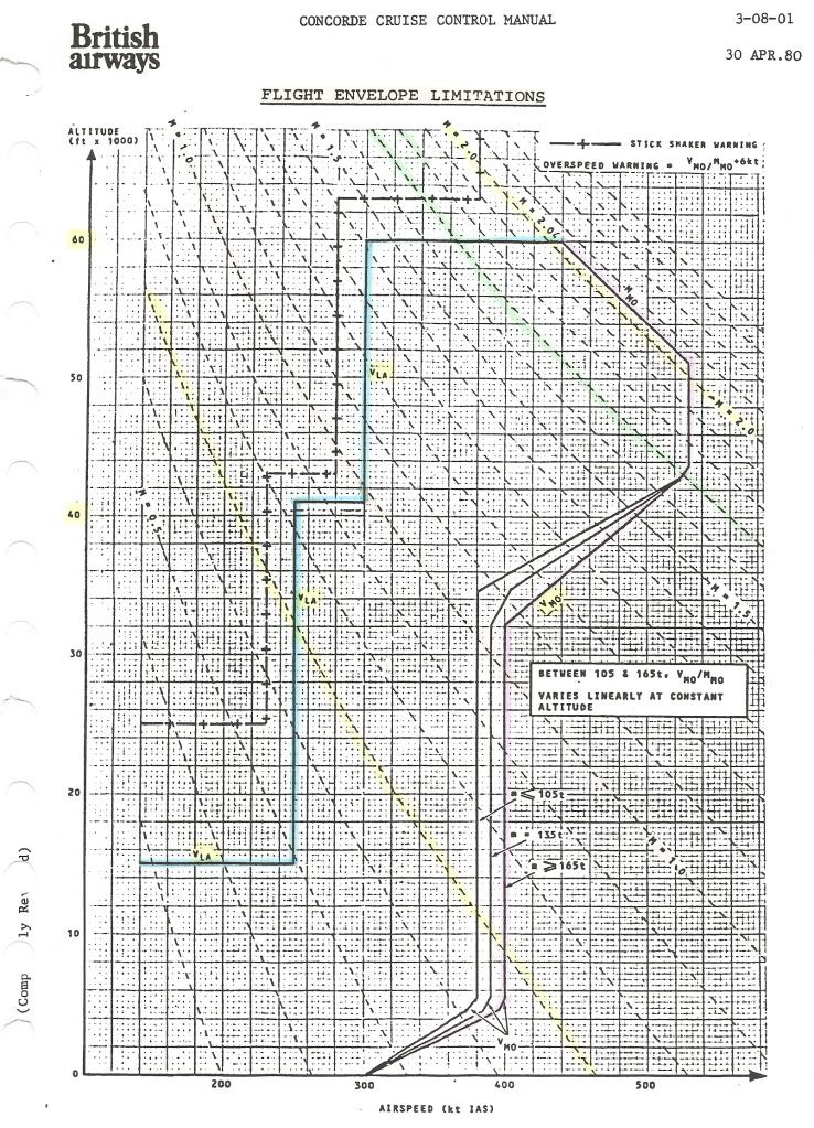
... The subsonics have issues with Coffin Corner (I think I read that one Airbus model had somehting like 7kts between the high and low end of the envelope when up high); did Concorde have this "problem"?...
Have a look at this picture of G-BOAE, cruising at her maximum certificated altitude of FL600, en-route to Barbados on 16 August 2003:
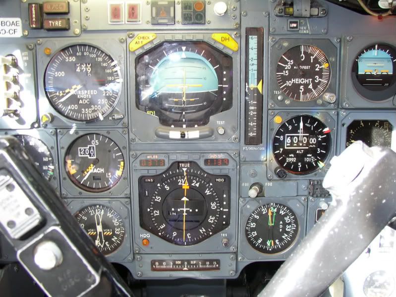
The available IAS speed range is shown on the ASI, and lies between the yellow and black Barbers Pole, currently indicating 440kts, and the white bug set to 300kts, the VLA ( L owest A uthorised speed) at this altitude.
The available Mach speed range is shown on the Mach meter, and lies between the yellow and black Barbers Pole, currently indicating M2.05, and the yellow bug which indicates the lowest Mach number allowed for the current aircraft CG position (the AFT limit) currently showing M1.35.
So, given that at her maximum altitude she had a speed range of 140kts IAS and a Mach range of M0.7, we can see that coffin corner was not a problem!
main_dog
...I too would like to ask what her idle thrust glide ratio was...
By my calculations, the figures quoted for a straight in approach, give an average glide ratio of around 20:1, however these were for a standard decel/descent, and on Concorde the early part of the decel/descent was not flown at idle power.
A considerable amount of power was left on initially, around 94% N2, for various reasons, and only below M1.0 were the throttles usually selected to idle.
I hadn’t noticed it until now but there does not appear to have been a chart giving glide distance at idle thrust!
However, since the speeds to be flown during the “4 Eng Flame Out” procedure were not too far from the normal decel/descent speeds, I’ll hazard a guess (and that is all it is) that the glide distance from FL600, with no thrust, would have been about 150nm, giving a glide ratio of around 15:1.
Subjects
Airbus
Barbados
British Airways
C of G
Captains
FL600
G-BOAE
Glide
IAS (Indicated Air Speed)
Links are to this post in the relevant subject page so that this post can be seen in context.
Reply to this quoting this original post. You need to be logged in. Not available on closed threads.
August 22, 2010, 15:35:00 GMT
permalink Post: 5885694
It shows the emergency descent profile (solid line, 'Avion'), and the resulting effect on the cabin altitude (dotted lines) in the cases of one window ('hublot') blowing out with either three or four air conditioning packs ('groupes') operating.
As the graph shows, in the worst case the cabin altitude rises to about 40,000ft for about two minutes before starting to drop again, which is survivable when breathing oxygen.
It was studies like this, that lead to the small windows on Concorde. Keen spotters may actually notice that the windows on the prototypes are bigger than on all the other aircraft

The diagram is taken from "The Concorde Story" by Chris Orlebar, but the original was so pale that it was uncopyable, so I did redraw it, in answer to a question by a French friend (hence the legends in French).
Subjects
Depressurisation
Links are to this post in the relevant subject page so that this post can be seen in context.
Reply to this quoting this original post. You need to be logged in. Not available on closed threads.
August 24, 2010, 23:00:00 GMT
permalink Post: 5890366
 Our first minicomputers - to reconstruct the CT image - had 32
kilobytes
of memory on four boards, each about 17" square!!
Our first minicomputers - to reconstruct the CT image - had 32
kilobytes
of memory on four boards, each about 17" square!!
You were already working with advanced stuff, Roger...
The notorious AICU (air intake control unit) had something like 2 kilo bit RAM, and 42 512- bit PROMs on 5 boards. That's a grand total of 2688 bytes of program storage, look-up tables, etc.
I can only make a stab in the dark, but ... I would say (mentally totting up all the electronics boxes and weighing them) the electronics fit weighed in the order of a couple of tons (maybe somebody has a closer figure?). So on an aircraft of 185T TOW, even if you could bring that down to a quarter of that weight, you'd gain less than 1%.
How much more capable?
Concorde did fine, so what more capability do you want ?
Seriously, you would have a glass cockpit, which would make nav etc. easier.
And of course you would be able to get rid of the flight engineer and his panel, so that would be a few more hundred kilos.... beer and all.
Where an electronics update would make a difference would be in the amount of aircraft wiring. In the olden days, every single signal had its own bit of wire... now everything passes via digital 'buses', where dozens of signals are transmitted over a single twisted pair.
For the computer and electronics buffs among you : it's the difference between the old Centronics printer interface, where every signal has its own wire, and todays USB.
CJ
Subjects
AICU (Air Intake Control Computer)
Auto-throttle
Intakes
Links are to this post in the relevant subject page so that this post can be seen in context.
Reply to this quoting this original post. You need to be logged in. Not available on closed threads.
August 25, 2010, 15:30:00 GMT
permalink Post: 5891668
I have the rare privilege of actually having one of those rare "secret" air intake computers (AICU) sitting right next to my desk.
The circuit boards are mostly quite neat, with only the odd wire strap here and there.
However, the wiring of the unit itself, between the connectors, is a nightmare.
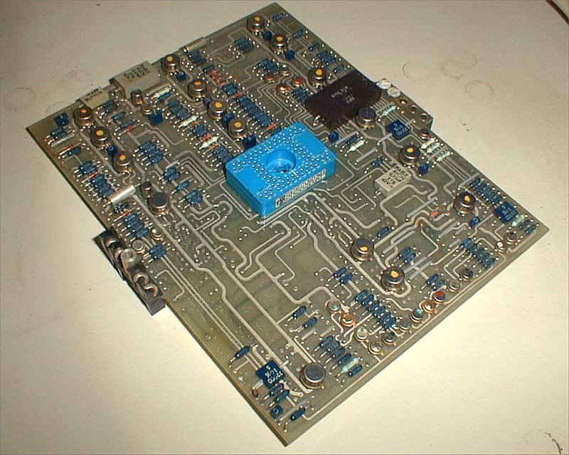
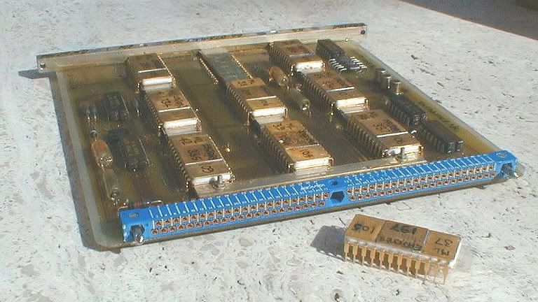
This is one of the PROM boards from the AICU, with one of the PROMs taken out of its socket. I have more photos, but will have to download those first, if anyone is interested.
Landroger
Don't forget that all the computing in the AFCS computers was analog, not digital!
The vast majority were LM101As, with 741s in non-critical locations, and the odd LM108 for the really hiigh-precision stuff.
We did not always do the kind of "butcher job" I described for the A/T. If there was enough time between major mods, the "firm" would redesign the board(s) and send us a new set, and the old ones would be binned... it made for better reliability. I kept a few as souvenirs.
It's the big blue "thing" at the centre of the board, with no less than 80 pins.
This is the back of the card
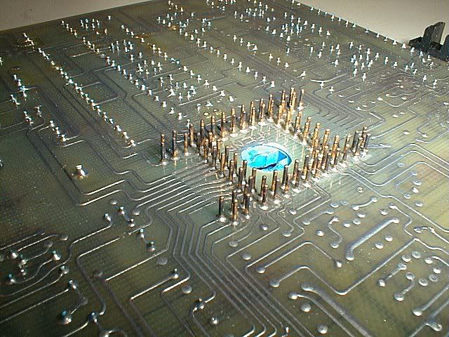
This is the central connector closer up
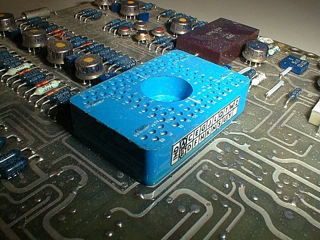
The idea wasn't bad at first sight.... it allowed stacking three boards on top of each other, so that many signals could pass from one board to another without any intermediate wiring. A small motherboard with a fourth conector would then take certain signals to other stacks, etc.
Another claimed advantage was that it made the board layout easier.
What was learned only gradually was that those connectors were hideously difficult to solder in place, and even more difficult to repair. Concorde was too far "on the way" to redesign the entire AFCS, so we learned to live with them, but the concept was abandoned afterwards.
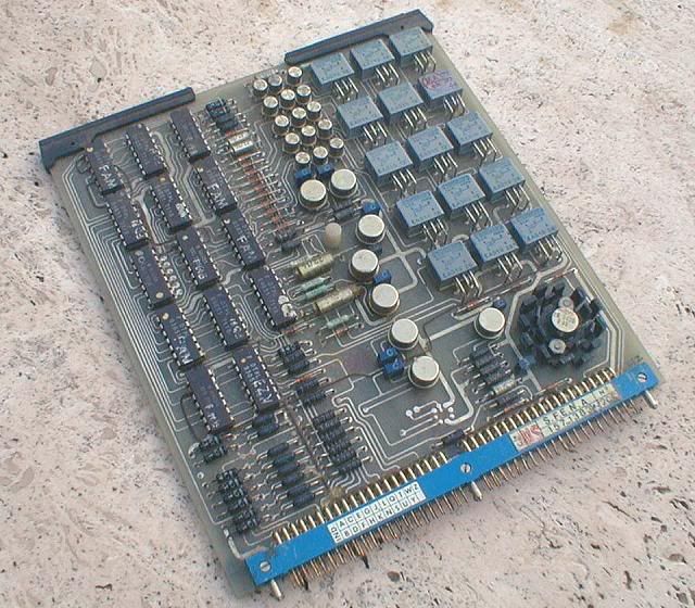
The central connectors were only used for the analog boards ; the logic boards used more conventional 84-pin connectors on one side.
This is one of the logic boards.
Re the weight question, I would say M2dude 's answer is a lot better than mine, so ignore my remarks.....
Re the wiring, Concorde had about 300km of it.
IIRC the A380 Flying Hippo, which is vastly bigger, "only" has about 500km of wiring, and it seems a lot of that is the IFE (in-flight entertainment)

CJ
Subjects
AFCS (Automtic Flight Control System)
AICU (Air Intake Control Computer)
Intakes
Links are to this post in the relevant subject page so that this post can be seen in context.
Reply to this quoting this original post. You need to be logged in. Not available on closed threads.
September 06, 2010, 12:52:00 GMT
permalink Post: 5917084
Is this what you're looking for?
Best Regards
Bellerophon
Subjects
Flight Envelope
Links are to this post in the relevant subject page so that this post can be seen in context.
Reply to this quoting this original post. You need to be logged in. Not available on closed threads.
September 06, 2010, 14:40:00 GMT
permalink Post: 5917319
Re the flight envelope diagram, Bellerophon got ahead of me, and his scan is cleaner than mine!
I've got a second one, which is basically the same, but has the envelope for a CG of 55% and for a CG of 59% hatched in.
For anybody who wants the full scans to print them out in A4, use these links.
Flight envelope A4 format
light envelope w. CG limits A4 format
Apologies for the mediocre quality of the scans...
CJ
Subjects
C of G
Flight Envelope
Links are to this post in the relevant subject page so that this post can be seen in context.
Reply to this quoting this original post. You need to be logged in. Not available on closed threads.
September 07, 2010, 07:12:00 GMT
permalink Post: 5918834
 Hi guys, here is a schedule showing CG against Mach number (It's very old just like the author here). I hope that it now completes our collection of flight envelope diagrams.
(
Bellerophon, by the way, your diagram is precisely the one that I was scouring around for). Great explanations by everybody on the Mach/TAS/IAS etc issue, mostly all clear and concise ( a couple of minor goofs that were subsequently corrected, otherwise very good) .
Hi guys, here is a schedule showing CG against Mach number (It's very old just like the author here). I hope that it now completes our collection of flight envelope diagrams.
(
Bellerophon, by the way, your diagram is precisely the one that I was scouring around for). Great explanations by everybody on the Mach/TAS/IAS etc issue, mostly all clear and concise ( a couple of minor goofs that were subsequently corrected, otherwise very good) .
If I were in the LEAST bit pedantic (and any here that know me would say that the b****d certainly IS
 pedantic), I would merely add that Concorde (like virtually all complex aircraft) relied on CALIBRATED airspeed (Vc) and not IAS, taking into acount plate and probe errors. Just as well I'm not pedantic
 .
.
Dude

Last edited by M2dude; 7th October 2010 at 18:12 .
Subjects
C of G
Flight Envelope
IAS (Indicated Air Speed)
Links are to this post in the relevant subject page so that this post can be seen in context.
Reply to this quoting this original post. You need to be logged in. Not available on closed threads.
September 07, 2010, 08:39:00 GMT
permalink Post: 5918963
Yes ChristaanJ, I FINALLY managed to upload stuff here.


Subjects
Afterburner/Re-heat
Nozzles
Olympus 593
Rolls Royce
Thrust Reversers
Links are to this post in the relevant subject page so that this post can be seen in context.
Reply to this quoting this original post. You need to be logged in. Not available on closed threads.
September 07, 2010, 13:27:00 GMT
permalink Post: 5919535
The production a/c diagram is slightly different, but it shows the same kind of "corridor".
Edit : here is the production a/c diagram.
Sorry for the distortion during the scan....
For the full A4 page, use this link :
Prod CG enevlope A4 format
CJ
Last edited by ChristiaanJ; 7th September 2010 at 15:16 .
Subjects
C of G
Links are to this post in the relevant subject page so that this post can be seen in context.
Reply to this quoting this original post. You need to be logged in. Not available on closed threads.
September 08, 2010, 20:52:00 GMT
permalink Post: 5922726
I think M2dude has already answered your question.
Anyway, herewith a few very crude scribbles to further illustrate your question and his answers.
Simplistically, an "old-fashioned" airplane has an asymmetric wing profile (at take-off even more so because of the flaps). Such a profile will start producing lift as soon as you start moving, and if you had enough take-off space, the aircraft would fly off the ground even without rotating it - in practice you rotate to get a more optimum angle of attack, more lift and a better climb speed to "get over the fence".
The Concorde wing, in the same circumstances, is little better than a big flat plank, and will not produce any lift at all, or at least far too little to carry the aircraft.
As M2dude already said, raising the elevons produces enough of a downforce at the trailing edge to lift the nose, and from there on the wing does start producing lift.
Not quite conventional lift, but "vortex lift" (a different subject), but lift just the same.
CJ
Last edited by ChristiaanJ; 8th September 2010 at 21:42 . Reason: Resizing a picture, typos
Subjects
Elevons
Vortex
Links are to this post in the relevant subject page so that this post can be seen in context.
Reply to this quoting this original post. You need to be logged in. Not available on closed threads.
September 12, 2010, 16:08:00 GMT
permalink Post: 5930300
As a Concorde fan for 10 years (since I bought FS2000), and passionate developer of SSTSIM Concorde and FSLabs ConcordeX (flight dynamics, weight and balance), it's simply awesome to have you guys and gal here sharing your memories.
Regarding the CG corridor, here's a fantastic graphic from online Concordepedia, aka ConcordeSST.com, Technical/Fuel System section:

Interestingly, it doesn't show a warning for CG>59.1% above M1.6, opposite to what M2Dude said earlier on the topic.
I got curious on the Max Climb/Cruise and ALT ACQ not being primed. How the levelling at FL600 was done? Manually?
Regarding the fuel tanks, specially tanks 6 and 8: did these tanks' lateral center of gravity change with quantity? Due to their completely assymetrical shape, I'd expect some change in it.
Operationial question: did BA use the 380kts descent profile? Have heard that only AFR used it, but Haynes' book says that BA started using it too.
There are many doubts regarding procedures as manuals and informations available on the internet are mostly from BA 1976 entry-into-service era. But i understand many things changed along the years, as I can see on a Aug 2000 manual I've got, with percentages showing differences from the 76 era, or even completely new tables.
Well, that's it, hope to be able to contribute on the topic, but mainly learn from you that flew the real thing.
Subjects
British Airways
C of G
FL600
Haynes guide to Concorde
Manuals
Links are to this post in the relevant subject page so that this post can be seen in context.
Reply to this quoting this original post. You need to be logged in. Not available on closed threads.
September 15, 2010, 15:40:00 GMT
permalink Post: 5936328
Was there ever any consideration given to fitting one and was the decision against the installation solely a weight issue ?
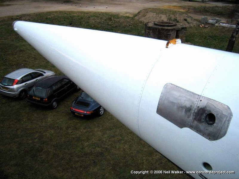
The subject was dealt with in some depth, and in the course of the discussion is was described how the two preproduction and the first two production aircraft were equipped with an MEPU (monopropellant emergency power generator).
I've only just found this photo again... it's the MEPU of Delta Golf (202 - G-BBDG).
The photo was taken after 'DG was moved to the Brooklands museum, but before the tail cone was put back into place.

CJ
Subjects
APU (Auxiliary Power Unit)
Brooklands
G-BBDG
MEPU (Monogol Emergency Power Unit)
Links are to this post in the relevant subject page so that this post can be seen in context.
Reply to this quoting this original post. You need to be logged in. Not available on closed threads.
September 16, 2010, 13:48:00 GMT
permalink Post: 5938152
I think it's a take-off, but not sure...

(I used this one as my screen background for a long time.)
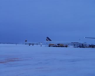
BA arrival (sorry for the quality, blown up from a tiny website pic, but it's a nice illustration of the atmosphere.

Both BA and Air France had their Santa Claus charters.
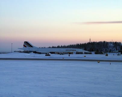
And sometimes they even met at Rovaniemi !
CJ
PS None of the photos are mine, but they're all public domain.
I'm sure there must be much better ones, but these are the only ones I had 'to hand'.
Subjects
British Airways
Links are to this post in the relevant subject page so that this post can be seen in context.
Reply to this quoting this original post. You need to be logged in. Not available on closed threads.
September 19, 2010, 18:10:00 GMT
permalink Post: 5943906
Jo90 ,
I'm no expert, so I cannot answer fully.
On a conventional wing, with a conventional profile, at subsonic speed, everything is done to keep the airflow 'attached' to the wing as long as possible, and for as high an angle of attack as possible.
Such a wing stalls because above a certain angle of attack the airflow 'breaks away' from the upper surface of the wing, leading to a sudden loss of lift.
On a very thin slender delta, the airflow already is made to detach right at the leading edge, even at low angles of attack.

Rather than "ruining" the airflow, hence the lift over the entire wing, the result is a vortex that rolls up and re-attaches the airflow to the wing.

At high subsonic speeds, hence low angles of attack, the vortex is located just behind the leading edge, and the rest of the wing produces "conventional" lift.
With lower speeds, hence higher angles of attack, the vortex grows , and ends up covering most of the wing during take-off and landing, as one sees in some photos.
So there is no real sudden transistion from "conventional" to vortex lift.
At no time does the vortex 'break away', so there is no stall in the conventional sense. However, drag increases rapidly, and controllability doesn't improve either, so there are still angle-of-attack limits, even on Concorde.
At supersonic speeds, the entire flow is totally different, and totally unlike the vortex flow.
My own question to an aerodynamicist would be :
Looking at the subtle camber of the leading edge, is there any vortex lift at all during subsonic cruise (Mach 0.95+) or is there a fully attached airflow at that speed / angle of attack to obtain the best possible subsonic cruise?
And if so, when does the breakaway first start?
CJ
Subjects
Vortex
Links are to this post in the relevant subject page so that this post can be seen in context.
Reply to this quoting this original post. You need to be logged in. Not available on closed threads.
September 19, 2010, 20:45:00 GMT
permalink Post: 5944131
She's not that unique.... there are many vintage and "heritage" aircraft flying in the UK.
But more than anything else, I think the Vulcan is about as far as the Campaign Against Aviation is willing to go in the UK in terms of a "complex aircraft".
With less obstruction, and some more work, I would have thought a Lightning could have flown in the UK.
A Concorde... no way.
Yes, in a better state than 'SD, overall, and again much less complex than Concorde, and more in the category of the Vulcan.
In her case, I would say it's before all a matter of money.
After the Falklands, the Vulcan, in a way, was THE icon among the V-bombers, and the money was raised to return her to the sky (and we know with what difficulties).
Somehow, I can't see that enough money can be found to return a second, less symbolic, V-bomber to flight, however much she's shown us she wants to!
(Yes, I've seen the videos... and I've had the pleasure to meet her in person at Bruntingthorpe a couple of years ago.)
And are you forgetting 'Canopus' ? An even sadder story.
The picture below is not a moon crater landscape but a capture from the video published by the museum.

Draw your own conclusions.
CJ
Subjects
LP Compressor
Links are to this post in the relevant subject page so that this post can be seen in context.
Reply to this quoting this original post. You need to be logged in. Not available on closed threads.
September 20, 2010, 17:06:00 GMT
permalink Post: 5945815

Subjects: None
No recorded likes for this post (could be before pprune supported 'likes').Reply to this quoting this original post. You need to be logged in. Not available on closed threads.
September 25, 2010, 14:17:00 GMT
permalink Post: 5955636

The sidestick was located where the LH weather radar display normally is.
CJ
Subjects
Sidestick
Links are to this post in the relevant subject page so that this post can be seen in context.
Reply to this quoting this original post. You need to be logged in. Not available on closed threads.