September 25, 2010, 22:03:00 GMT
permalink Post: 5956169
You're quite right, actually, especially assuming no flow.
"how would the fluid in the "cylinder" "know" it's pressing against pressurized hydraulic fluid in the inner tube and not a solid steel piston? "
The fluid wouldn't "know".. It would be pressing against pressurized hydraulic fluid further down the line.... but at the end, it would finally be pressing against the piston of a hydraulic cylinder of some kind at the end, like the 'cap' in my first scribble.
If nothing was restrained "downstream", indeed everything would be "blown apart".
Of course, that hydraulic cylinder (my 'cap') would be affixed to the structure, so it wouldn't move.
The problem is more like my second scribble.... with a bend in the pipe, and only the final 'cap' fixed, the pipe would continuously flex under pressure.... not a good idea at all, especially when the pressure in the pipe varies, because the 'cap' is not a real 'cap' but something like a PFCU (power flight control unit), with continously varying demand.
So yes, the hydraulic lines are restrained in all the right places, for the hydraulic expansion seals to work correctly without setting up stresses in the lines themselves (except for the pressure acting outwards, of course).
Hope this makes sense to you?
CJ
Subjects
Expansion
Hydraulic
PFCU (Powered Flying Control Units)
Links are to this post in the relevant subject page so that this post can be seen in context.
Reply to this quoting this original post. You need to be logged in. Not available on closed threads.
September 28, 2010, 22:58:00 GMT
permalink Post: 5962512
Nevertheless there were three separate sets of landing/taxi lights there.
Quoting from the manual:
Two main landing lamps, one mounted in each wing root leading
edge, have retractable/extensible mountings and when not in
use are retracted in the lamp housing.
Two land/taxi lamps, similar to the main landing lamps, are attached to the
nose landing gear bay doors. The land/taxi lamps extend to
an intermediate position for landing, upon which they
automatically extend to the full position for taxiing, thus
changing the beam angle to compensate for the attitude change.
Two taxi/turn-off lamps, one mounted on each side of the
forward fuselage, provide ground illumination to identify
runway turn-off points.
These are the 'main' lights in the wing leading edge (600W each).
These are the lights in the nosewheel doors ("only" 450W each).

The heat was less of a problem, actually.
The lights themselves were high-power sealed-beam units, the main units were 6 00W each, and the ones in the nosewheel doors were 450W ... nothing like your car headlights.
As a matter of fact, on the ground you were not suppossed to turn them on any more than 5 minutes in any 10 minutes.... they got a lot hotter when switched on, than they did in supersonic flight.
What happened was that the main landing lamps in the wing roots were angled such, that they pointed straight ahead at the right angle to "hit" the runway during the landing itself.
Once the aircraft touched down, the land/taxi lights in the nose gear door extended further and lit a wider expanse of the runway ahead (see the earlier quote from the manual).
And then the third set of lights in the nose helped you to find the turn-off to the taxiway.
One nice little detail.... on F-BTSD, the Concorde at the French Le Bourget museum, those lights still work, and on G-BBDG, the Concorde at the Brooklands museum that was saved from the scrapheap, they brought those lights back to life, too.
CJ
Last edited by ChristiaanJ; 28th September 2010 at 23:14 . Reason: Addng pics and typo
Subjects
Brooklands
F-BTSD
G-BBDG
Landing & Taxy Lights
Landing Gear
Le Bourget
Links are to this post in the relevant subject page so that this post can be seen in context.
Reply to this quoting this original post. You need to be logged in. Not available on closed threads.
September 29, 2010, 14:38:00 GMT
permalink Post: 5963836
Judging by the picture from the maintenance manual below, once the nosewheel was down, the main landing lights just lit up the ground below the nose, but not ahead.
Did you just rely on the runway lighting plus the ambient light (town lights reflected by the clouds, etc.) or did you usually extend the nosewheel door lights once you were down?
CJ
Subjects
Landing & Taxy Lights
Landing Gear
Links are to this post in the relevant subject page so that this post can be seen in context.
Reply to this quoting this original post. You need to be logged in. Not available on closed threads.
October 08, 2010, 09:06:00 GMT
permalink Post: 5981420
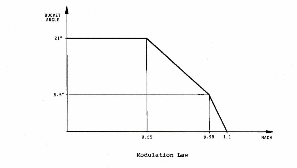
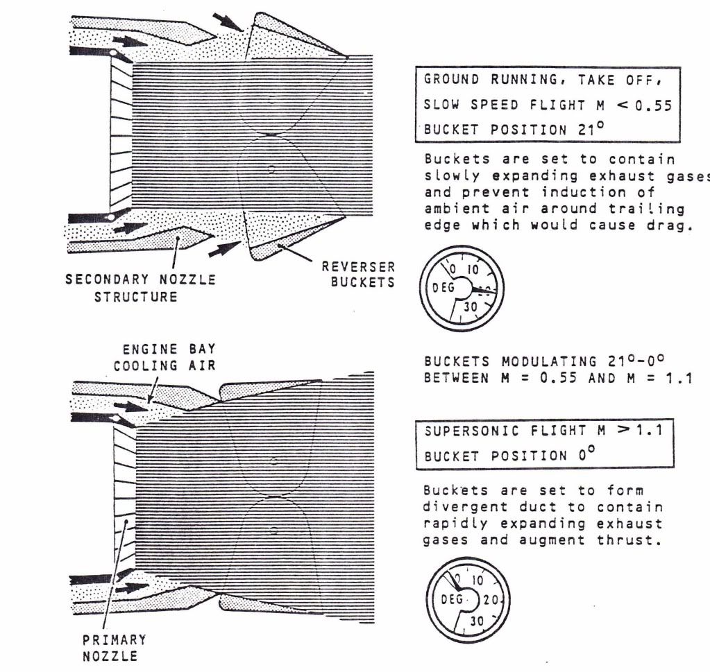
Now if we are locked at the 10 degree position we are at a position that will give us significant but tolerable losses throughout the flight envelope.
Subjects
Expansion
Flight Envelope
Intakes
Nozzles
Thrust Reversers
Links are to this post in the relevant subject page so that this post can be seen in context.
Reply to this quoting this original post. You need to be logged in. Not available on closed threads.
October 09, 2010, 19:10:00 GMT
permalink Post: 5984488
The story I heard when I was an apprentice at Hurn was that, compared to the prototype multi finger nozzle and separate reverser, the production nozzle was:-
1. More efficient.
2. Lighter.
3. Simpler.
4. Cheaper to make and maintain.
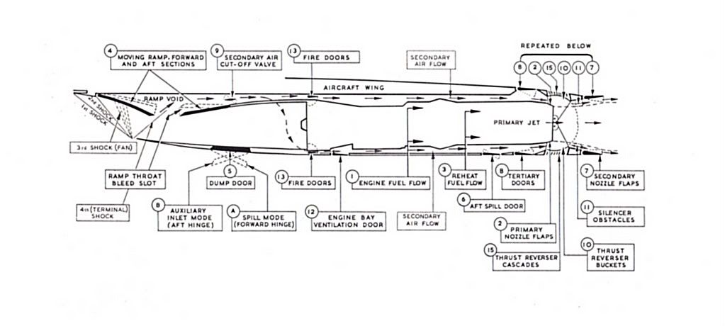
The original secondary nozzle was 'freely floating, with no actuation; the thrust revereser itself was a pair of cascade doors, driven by an air motor. Tertary air doors opened at low speeds to admit ambient air into the nozzle anulus, instead of the eyelids of the later 'buckets'.
If you look at the diagram below you can see what a complicated animal the prototype powerplant was. The intake dump door (alternative name for spill door) was hinged both at the front AND the rear; either hinge mechanisms automatically releasing at specific Mach numbers. It was the mechanical nightmare that the diagram suggesrs.
Dude

Last edited by M2dude; 9th October 2010 at 21:54 .
Subjects
Intakes
Nozzles
Rolls Royce
Thrust Reversers
Links are to this post in the relevant subject page so that this post can be seen in context.
Reply to this quoting this original post. You need to be logged in. Not available on closed threads.
October 19, 2010, 08:13:00 GMT
permalink Post: 6003630
Twenty-two.
Two static-test airframes.
- One at Toulouse , for purely static tests, and tests such as vibration and flutter.
Left Upper Wing Skin
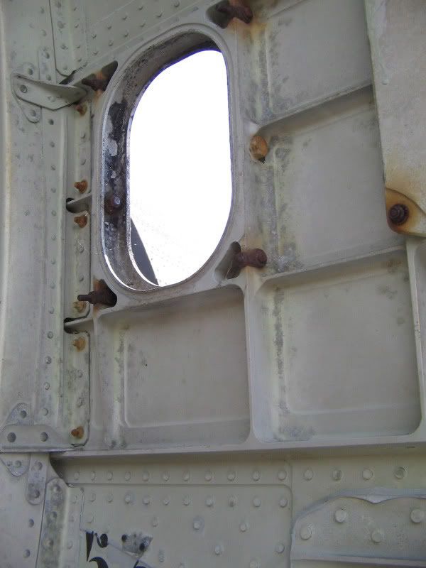
Right hand passenger window, rear fuselage
Seat tracks, forward cabin looking aft
At least it was in 2008, maybe it has been scrapped in favor of the A350 production line by now.
Subjects
Toulouse
Links are to this post in the relevant subject page so that this post can be seen in context.
Reply to this quoting this original post. You need to be logged in. Not available on closed threads.
October 20, 2010, 10:21:00 GMT
permalink Post: 6006321
Ess 28v DC Busbar -> Fwd Thrust Selected -> Arming Switch 'On' -> Landing Gear Relay Operated -> Fuel Flow Attained -> Jet Pipe Pressure (P7) Attained -> Bucket Position Correct -> 'GO'.
How were these engine parameters monitored? (From the AMM)
- Arming Switch 'ON' : it's a manually operated four-pole solenoid-held switch, for the four engine circuits, operative only when a landing gear weight switch is energized.
- Fuel Flow and Jet Pipe Pressure (P7) Attained: Once the circuit to the 'Go' light is armed, the flow and pressure are monitored against the values set on the indicator bugs on the respective instruments. Once they pass those values, their respective change-over relays are energized, completing the circuit.
Here's a simplified schematic for this:

At least I think that's how it works
 .
.
Lefteris
Subjects
Fuel Burn
Landing Gear
Thrust Reversers
Links are to this post in the relevant subject page so that this post can be seen in context.
Reply to this quoting this original post. You need to be logged in. Not available on closed threads.
October 24, 2010, 22:18:00 GMT
permalink Post: 6015446

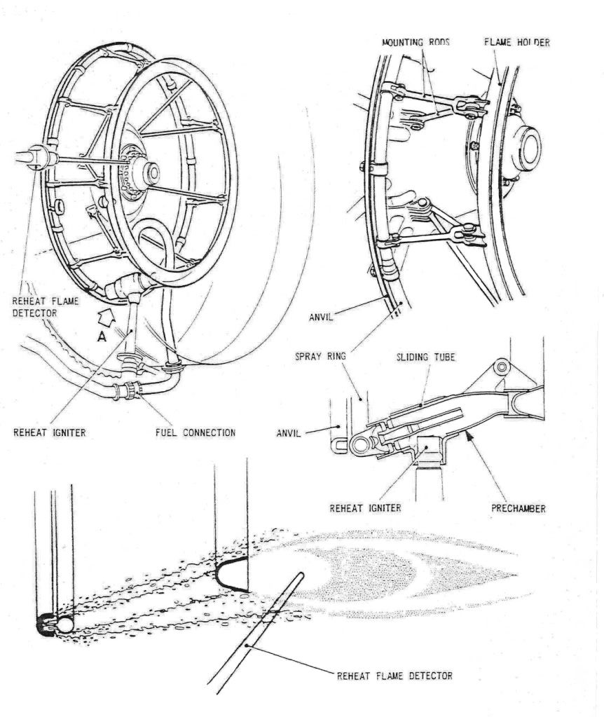
As promised, here are a few diagrams of the Concorde reheat (afterburner, for our American friends) system. The ORIGINAL design was done by SNECMA, but due to them getting into all sorts of trouble with the fuel injection system and flame stabilisation, Rolls Royce baled them out, and it became a Rolls Royce/SNECMA design. (The core engine was a 100% Rolls design, with no French input whatsoever. However some engine sub-assembles were manufactured by SNECMA).
The basic way the afterburner worked was by spraying the fuel FORWARDS intially at high pressure, against the jet stram about one inch, until it hit the anvil. . As the fuel strikes the anvil it is blown back by the jet stram and atomises, passing over the of the spray ring and the over the flame holder. The ignition operated by passing 15KV across a dual cylindrical tube, the resulting arc was 'swirlied' into the fuel stream by blowing engine 5th stage HP compressor air into the tube (there were 7 stages in all).
The key to successful ignition was a healthy spark, a good supply of air to the ignitor and accurate scheduling of fuel flow. (This was scheduled against dry engine flow as a funtion of total temperature). The other important factor (as with any afterburner) was correct and rapid operation of the exhaust nozzle. Fortunately, Concorde used it's primary nozzle for control of engine N1 anyway, so adapting this to operate as an afterburning nozzle also was a relative walk in the park, and it operated superbly.
During the light up phase of 3.5 seconds, the fuel ratio is a fixed 0.45 (ie. reheat fuel is 45% of dry fuel). After the light up phase the full scheduling commenced. As far as the FLIGHT RATING figures go (not take-off) the ratios were 0.6 at a TAT of 54 deg's C, falling linearly to 0.3 at 107 deg's C and above. (Remember that Concorde used afterburning really sparingly, just for take-off and then transonic acceleration; cut off at Mach 1.7 altogether.
Dude
Subjects
Afterburner/Re-heat
Fuel Burn
HP Compressor
Ignitors
N1 (revolutions)
Nozzles
Rolls Royce
TAT (Total Air Temperature)
Transonic Acceleration
Links are to this post in the relevant subject page so that this post can be seen in context.
Reply to this quoting this original post. You need to be logged in. Not available on closed threads.
October 25, 2010, 22:06:00 GMT
permalink Post: 6017288
 ) it was 2 1/2 minutes. (The only time that I can recall the limit being accidently exceeded we told Rolls Royce who after a few minutes of head scratching came back with a 'no problem man, don't worry about it
).
) it was 2 1/2 minutes. (The only time that I can recall the limit being accidently exceeded we told Rolls Royce who after a few minutes of head scratching came back with a 'no problem man, don't worry about it
).
Regards
Dude
Last edited by M2dude; 25th October 2010 at 22:22 .
Subjects
Rolls Royce
Links are to this post in the relevant subject page so that this post can be seen in context.
Reply to this quoting this original post. You need to be logged in. Not available on closed threads.
October 27, 2010, 08:20:00 GMT
permalink Post: 6020017
Maybe VOLUME can tell us more?
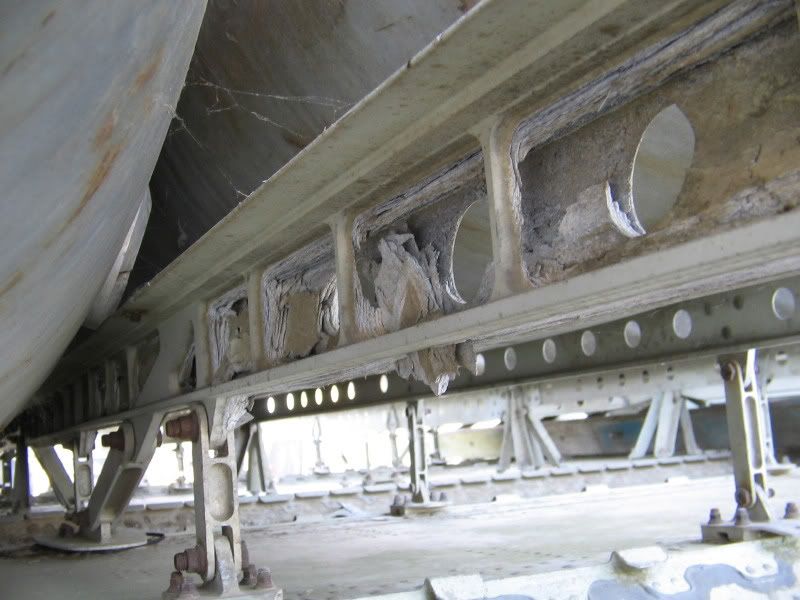
Found one more picture...
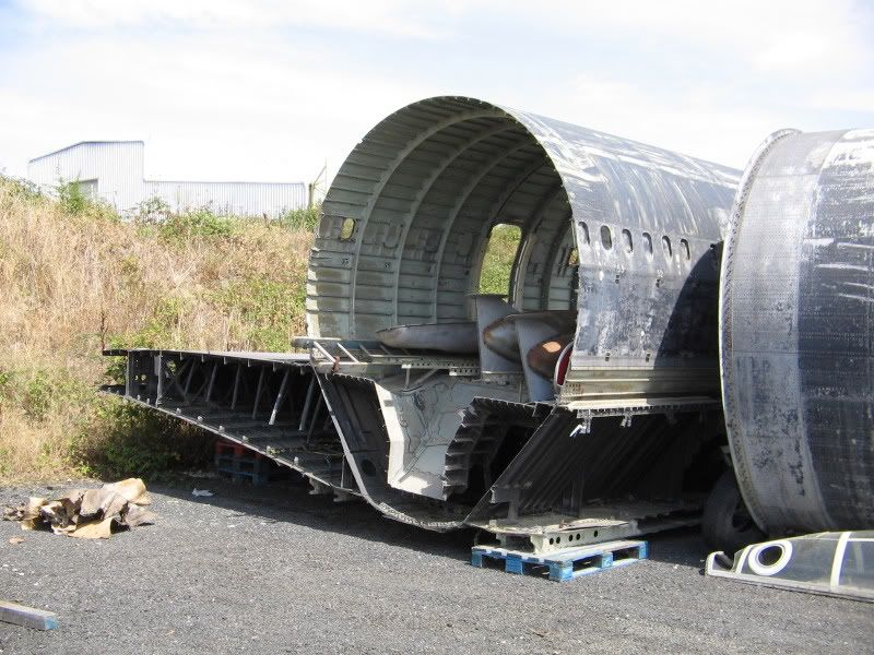
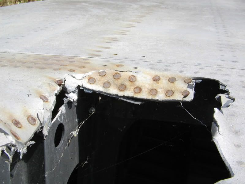
Sad to see this masterpiece of engineering rotting away.
I always thought that the sloped area at the aft end of the floor was the rear airstair (just present on the pre-production aircraft), but I just read on heritageconcorde.com/ that this is for "system routing". Does somebody know more ? Seems to be a lot of space for systems that would end just in the middle of the cabin.
Subjects
Toulouse
Links are to this post in the relevant subject page so that this post can be seen in context.
Reply to this quoting this original post. You need to be logged in. Not available on closed threads.
October 28, 2010, 15:26:00 GMT
permalink Post: 6022968
Here are the drawings that should help with your last photo of Concorde "0001".
Not very good quality, since they're scans of xerox copies of xerox copies of microfilm ...
Prototype drawing dated July 1965, which in particular shows the location of the emergency exits.
Production drawing (two cut-outs from the same drawing at the same scale) which (schematically) does actually show the 'sloped areas' both at the front and the rear of the main landing gear bay.
Note 1 : both frame 54 and frame 60 were 'production breaks'.
Note 2 : the tanks were numbered differently on the prototypes ; tank N\xb0 9 on the prototype became tank n\xb0 6 on the production aircraft.
CJ
Subjects
Landing Gear
Links are to this post in the relevant subject page so that this post can be seen in context.
Reply to this quoting this original post. You need to be logged in. Not available on closed threads.
November 10, 2010, 15:43:00 GMT
permalink Post: 6051953
)

As an example, F-BVFC at Toulouse, which was the last one to remain at least taxyable, now has some patches of corrosion starting to show, when you know where to look. Not to mention the nasty smell of damp and mould in the cockpit which bodes no good for what's going on underneath the floor.
And even F-BTSD, kept "live" to some extent at Le Bourget, leaks some hydraulic fluid (like all Concordes did on the ground), so it's easy to imagine the dried-out hydraulic and fuel seals on the other museum aircraft.
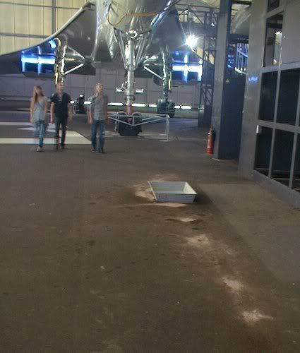
And yes, that's kitty litter...
The composite material of the floor and the hydraulic fluid don't agree too well.
CJ
Last edited by ChristiaanJ; 14th November 2010 at 11:32 . Reason: typo
Subjects
Air France
British Airways
Cabin Crew
Captains
Corrosion
F-BTSD
F-BVFC
Hydraulic
Le Bourget
SR-71
Toulouse
Tu-144
Tyres
Links are to this post in the relevant subject page so that this post can be seen in context.
Reply to this quoting this original post. You need to be logged in. Not available on closed threads.
November 18, 2010, 12:25:00 GMT
permalink Post: 6069344
The use of E LOW above 220KIAS was not only strictly inhibited by the automatics, if you over-rode the automatics and 'hard selected' E LOW , the aircraft would fall out of the sky when reheat was cancelled at Mach 1.7. This was because the low N1/√θ scheduled by E LOW would now invoke an N2/√θ limit (The E3 Limiter in the diagram) and claw off fuel flow by the tonne.
The most efficient schedule for supersonic cruise was E HI which again would be automatically selected.
E-MID was automatically selected during afterburning operation, to minimise the chance of an N1 overspeed on cancellation of reheat. E-MID could also be selected by the E/O for noise abatement approach.
E Flyover was as we discussed before used for take-off flyover noise abatement as well as subsonic cruise if desired. (If Mach 1 was exceeded with E Flyover still selected, a yellow NOZZLE light illuminated and E HI would be automatically selected.
I sincerely hope that this blurb is not clear as mud, feel free to ask away.
=> higher Fuelflow require to keep N2 run at constant speed]
).
Regards
Dude

Last edited by M2dude; 18th November 2010 at 15:04 . Reason: I goofed.. (another sign of age)
Subjects
Afterburner/Re-heat
British Airways
Fuel Burn
LP Turbine
N1 (revolutions)
Noise Abatement
Nozzles
Rolls Royce
Vortex
Links are to this post in the relevant subject page so that this post can be seen in context.
Reply to this quoting this original post. You need to be logged in. Not available on closed threads.
November 25, 2010, 16:11:00 GMT
permalink Post: 6083842
The 593s on the prototypes had eight separate combustion chambers, and used fuel injectors ; the smoke resulted from the less-than-perfect combustion (as on many earlier aircraft types).
The 593s on the pre-prod and the later production aircraft had a single 'annular' combustion chamber and fuel vaporisers (the fuel entered the gas stream fully vaporised rather than as a fine spray).
While it didn't totally eliminate the smoke (as any take-off video shows...), it did make a huge difference.
It was unfortunate, that the new engines were not there in time for the prototypes, so that during the prototypes' world tours they acquired a repution of 'Smoky Joes', and gave an un-needed and undeserved boost to the tree-huggers of the time.
CJ
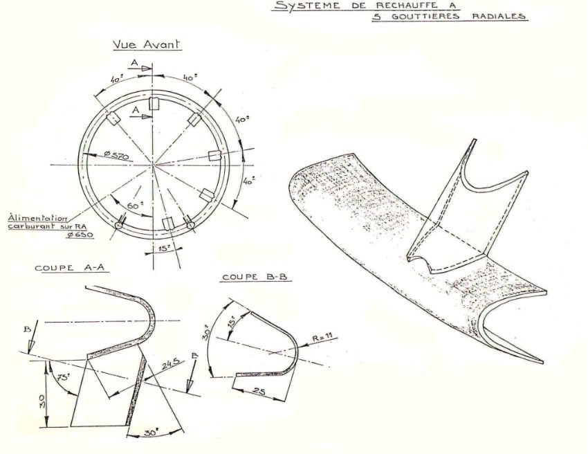
PS Here's another explanation....
(And no, the drawing isn't mine)
Last edited by ChristiaanJ; 25th November 2010 at 16:57 .
Subjects
Olympus 593
Links are to this post in the relevant subject page so that this post can be seen in context.
Reply to this quoting this original post. You need to be logged in. Not available on closed threads.
November 27, 2010, 18:30:00 GMT
permalink Post: 6087916
Not to mention the vast quantity of spare compressor and turbine blades and stator vanes, spread far and wide after the end-of-service, through the spare parts auctions.
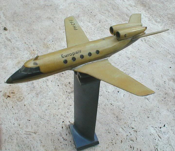
(The model is a design that was part of my engineering studies - late '60s - but the compressor vane is real Concorde.)
M2dude and myself already have mentioned the same problem with the AICU (air intake control computer) in this thread.
People do only rarely realise how rapidly technology was changing in the early Concorde days, and how difficult it was to procure components that sometimes were already obsolete when Concorde entered service.
CJ
Subjects
AICU (Air Intake Control Computer)
Intakes
Links are to this post in the relevant subject page so that this post can be seen in context.
Reply to this quoting this original post. You need to be logged in. Not available on closed threads.
November 29, 2010, 09:01:00 GMT
permalink Post: 6090430
Out of interest...here is a pic of AG in Seattle ( taken a while back ) and the source of a big part of this thread - unfortunately could not get any higher in order to get a better view...on either end ! ( I need to check on her again and see how she is doing ) and the SR71 also ( from the Pima Air / Space museum in Arizona) - I am sure all have seen the Concorde intakes but the SR71 rear end is interesting....
ps Please forgive the pic of the Sikorsky ( at Pima also ) ...couldnt resist
Cheers...
Subjects
Intakes
SR-71
Links are to this post in the relevant subject page so that this post can be seen in context.
Reply to this quoting this original post. You need to be logged in. Not available on closed threads.
November 29, 2010, 21:36:00 GMT
permalink Post: 6091728
Some of it can now be told.....
From the secret archives.
CJ
Subjects
Air France
Links are to this post in the relevant subject page so that this post can be seen in context.
Reply to this quoting this original post. You need to be logged in. Not available on closed threads.
November 29, 2010, 21:41:00 GMT
permalink Post: 6091743
Subjects: None
No recorded likes for this post (could be before pprune supported 'likes').Reply to this quoting this original post. You need to be logged in. Not available on closed threads.
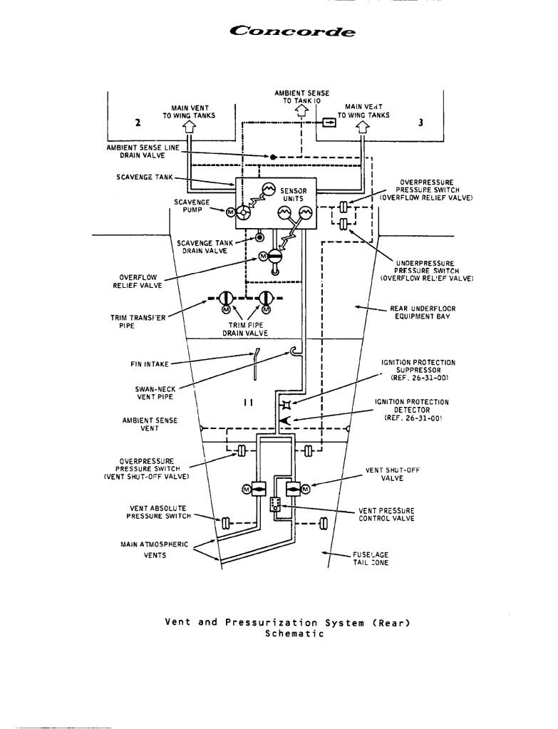
December 01, 2010, 11:32:00 GMT
permalink Post: 6094864

Regards Dude
Subjects
Fuel Vent System
Intakes
Trim
Vortex
Links are to this post in the relevant subject page so that this post can be seen in context.
Reply to this quoting this original post. You need to be logged in. Not available on closed threads.
December 14, 2010, 21:57:00 GMT
permalink Post: 6122266
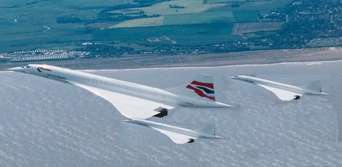
And yes, Concorde evokes images like no other aircraft really does.
Funnily enough, to me the image you describe always evokes something totally different... although it does depend on the exact angle it's taken from.
Seen from exactly the right angle, she has this slight 'smile' on her face, saying "did it again, people... home soon ! ".
Otherwise, oh yes, I have two images.... both sad.
One is the air-to-air video of the Jubilee flypast with the Red Arrows (I don't have the link at hand), when she pulls up and away, saying goodbye.
For some reson, I have never been able to watch that one without a huge lump in my throat.
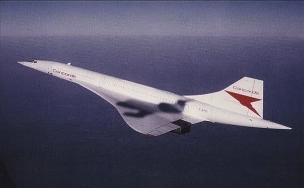
The other one is this one....
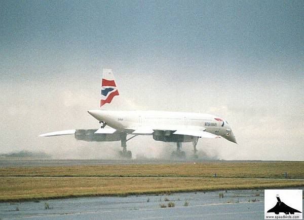
Last time ever.... and somehow one hoped an instant she would disappear from view, and return forever to the sky where she belonged.
And why should I now be furiously rubbing my eyes?
But maybe that answers your question, too....
Christian
Subjects: None
No recorded likes for this post (could be before pprune supported 'likes').Reply to this quoting this original post. You need to be logged in. Not available on closed threads.