December 15, 2010, 14:57:00 GMT
permalink Post: 6123526
A more cheerful image !
CJ
Subjects: None
No recorded likes for this post (could be before pprune supported 'likes').Reply to this quoting this original post. You need to be logged in. Not available on closed threads.
December 20, 2010, 08:43:00 GMT
permalink Post: 6132724
 ). The time and effort spent to share stories and knowledge is truly appreciated and no doubt an appropriate reflection on the brilliance that was Concorde. To everyone that was part of the Concorde dream you have my deepest admiration. Have yourselves a safe and fabulous holiday wherever you are. Looking forward to reading many more great posts in the coming year.
Thanks for keeping the memory of our GREAT ICON truly alive. She was a beauty !


cheers !
Subjects: None
No recorded likes for this post (could be before pprune supported 'likes').Reply to this quoting this original post. You need to be logged in. Not available on closed threads.
December 21, 2010, 09:35:00 GMT
permalink Post: 6135063

Sure, Concorde was the first aircraft to fly with FBW flight controls...
I thought it was the first civil aircraft, and that the Vulcan had already been there and done that ...
EXWOK
Mercifully no-one had thought of that when Concorde was being designed; I still think it's a diabolical system.
Best Regards
Dude

Subjects
Airbus
FBW (Fly By Wire)
Links are to this post in the relevant subject page so that this post can be seen in context.
Reply to this quoting this original post. You need to be logged in. Not available on closed threads.
December 21, 2010, 20:20:00 GMT
permalink Post: 6136200
The Mach trim control law
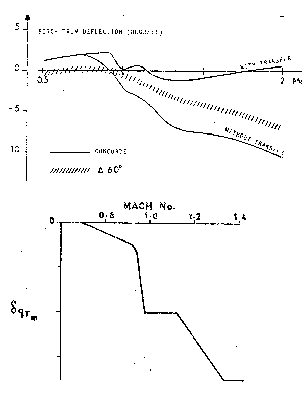
The aircraft response to a double engine surge
Split into two halves (longitudinal and lateral response)
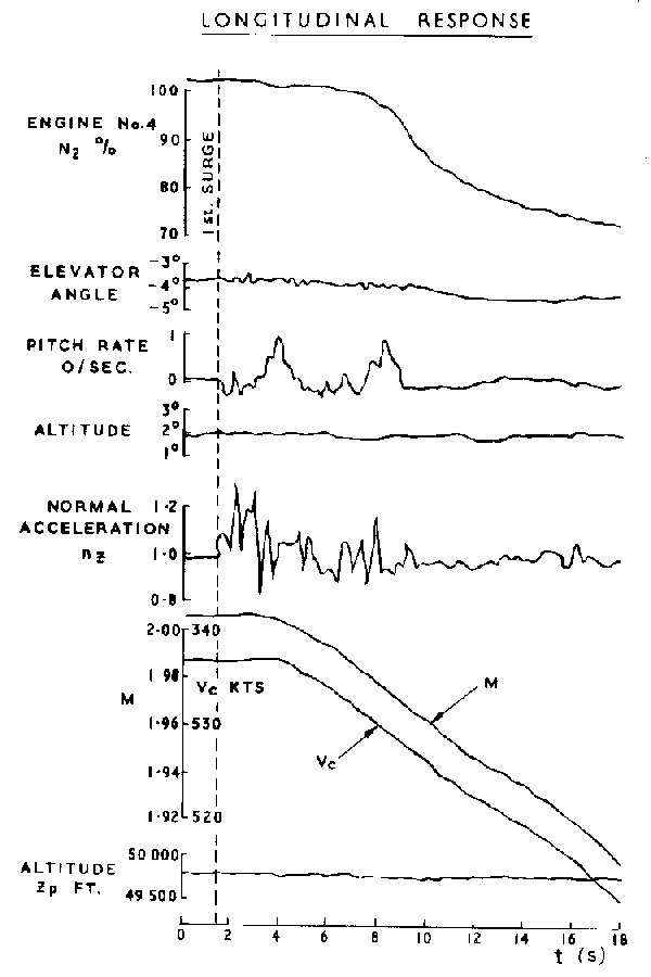
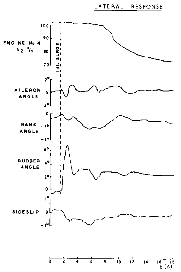
Note the almost immediate rudder response, long before the engine N2 rpm starts to wind down. I'll have something to say about that in a separate post....
CJ
Subjects
Engine surge
Mach Trim
Rudder
Trim
Links are to this post in the relevant subject page so that this post can be seen in context.
Reply to this quoting this original post. You need to be logged in. Not available on closed threads.
December 22, 2010, 14:50:00 GMT
permalink Post: 6137600
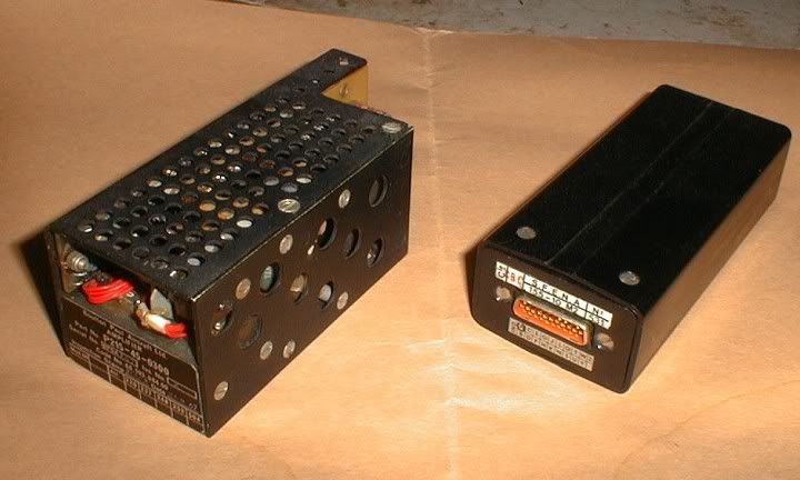
Pilot demands in manual flight produced electrical signals corresponding to the control position, which were sent to the 'servo control amplifiers' (eight in all, one per control surface) which in turn commanded the PFCUs (power flying control units) that hydraulically moved the control surfaces.
Autopilot demands directly moved the pilot's controls (stick and rudder) via hydraulic cylinders (the 'relay jacks') so that the same signals as in manual flight then went to the servo control amplifiers.
The purpose of the autostab was to provide proper dynamic stability over the full flight envelope. The aircraft could be flown without autostab, but over some of the speed range it was only marginally stable.
The electrical signals from the autostab computing were fed directly into the servo control amplifiers, so there was no feedback to the pilot's controls, unlike the autopilot demands.
There was occasional confusion about exactly what did what and how and where.... because the servo control amplifiers - although a function independent of the autostab as such - were housed... in the autostab computers.
To complete the tale, this is what those servo control amplifiers look like.
The one of the left is from prototype 002, the one on the right from a production aircraft. To give them scale, the one on the right is about the size of a box of large kitchen/fireplace matches.
CJ
Subjects
Auto-pilot
Auto-stabilisation
Flight Envelope
Hydraulic
Rudder
Links are to this post in the relevant subject page so that this post can be seen in context.
Reply to this quoting this original post. You need to be logged in. Not available on closed threads.
December 22, 2010, 15:40:00 GMT
permalink Post: 6137696
CliveL
Last edited by CliveL; 22nd December 2010 at 16:23 . Reason: add a picture
Subjects: None
No recorded likes for this post (could be before pprune supported 'likes').Reply to this quoting this original post. You need to be logged in. Not available on closed threads.
December 22, 2010, 20:40:00 GMT
permalink Post: 6138255
Closed loop
As an example, let's look (very simplified) at how the autopilot maintains a selected altitude.
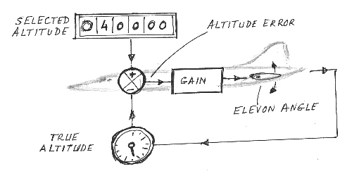
On the one hand we have the desired altitude as selected on the autopilot controller (here 40,000 ft).
On the other hand we have the true altitude , as measured by the altimeter (let's say 39,000 ft).
We subtract the two to obtain the altitude error (in this case 39,000-40,000=-1,000 ft).
We 'multiply' the altitude error by a factor, the gain (for the discussion, let's assume this gain is 1 degree elevon per 1000 ft altitude error), and send the resulting elevon position command to the elevon.
So, the elevon moves 1\xb0 nose-up, the aircraft starts to climb, the altitude increases and the altitude error decreases until it becomes zero, by which time the elevon position has also returned to zero.
What we have now is a "closed loop" : any deviation from the selected altitude results in an elevon command in the opposite direction, until the deviation is again reduced to zero.
Another commonly used term is "feedback" : any error is fed back in the opposite sense until it's reduced to zero.
The significant figure here is the 'gain'.
If the gain is too small, the autopilot response to a disturbance (say turbulence) will be sluggish ; the aircraft takes too long to return to the desired altitude.
If the gain is too high, a small disturbance will cause the aircraft to start climbing too rapidly, and to overshoot the desired altitude, then descend to correct the new error, etc.
In other terms, the control loop is no longer stable, but starts to oscillate.
Both theory and practice show that the exact value of the gain is not all that critical, a few percent more or less do not markedly change the response of the loop.
Note: a "closed control loop" as described above can be implemented in just about any way you like.
It can be done purely mechanically, with a few clever clockwork mechanisms 'computing' the altitude error and controlling the elevator pneumatically or hydraulically. It's how the earliest autopilots worked.
After that came electromechanical systems, analogue computers and then digital computers... but the principle has remained unchanged.
Open loop
As already described in earlier posts, the situation with the automatic trim is the opposite.
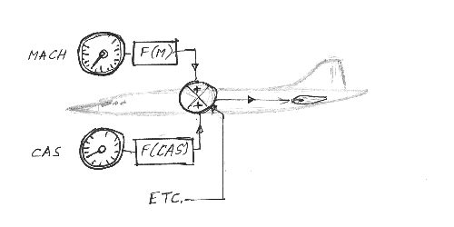
We now need to compute a neutral elevon position from several data, such as Mach number or airspeed, but without any feedback as to whether our computations are correct.
We're now working in "open loop".
To complicate matters... that neutral elevon position is not a simple linear function of Mach and airspeed, but far more complex (see the earlier posted graphs).
And because of the large response of the aircraft to small changes in trim, in particular in the transonic regions, those computations have to be far more accurate : a one degree error is simply not acceptable.
In the end.....
The AICS (air intake control system) also uses several "open loop" functions.
The early development aircraft still had an analogue system, which proved all too soon to be inadequate, so, at a very late stage, it was replaced by a digital system (one of the rare digital systems on Concorde).
The "open loop" functions of the autotrim system initially had the typical "a few" percent" accuracy of the other flight control systems, which, for the autotrim, also proved inadequate.
We managed to "save the furniture" (as they say in French) by using 0.1% components in all the critical computing paths, so the autotrim computers remained analogue until the end.
But, a slide rule is not accurate to 0.1%... So that's when I had to buy my very first pocket calculator.
\xa342 at 1972 prices... just as well the firm paid.
CJ
Subjects
AICS (Air Intake Control System)
Auto-pilot
Auto-trim
Elevons
Intakes
Trim
Links are to this post in the relevant subject page so that this post can be seen in context.
Reply to this quoting this original post. You need to be logged in. Not available on closed threads.
December 23, 2010, 08:31:00 GMT
permalink Post: 6138954
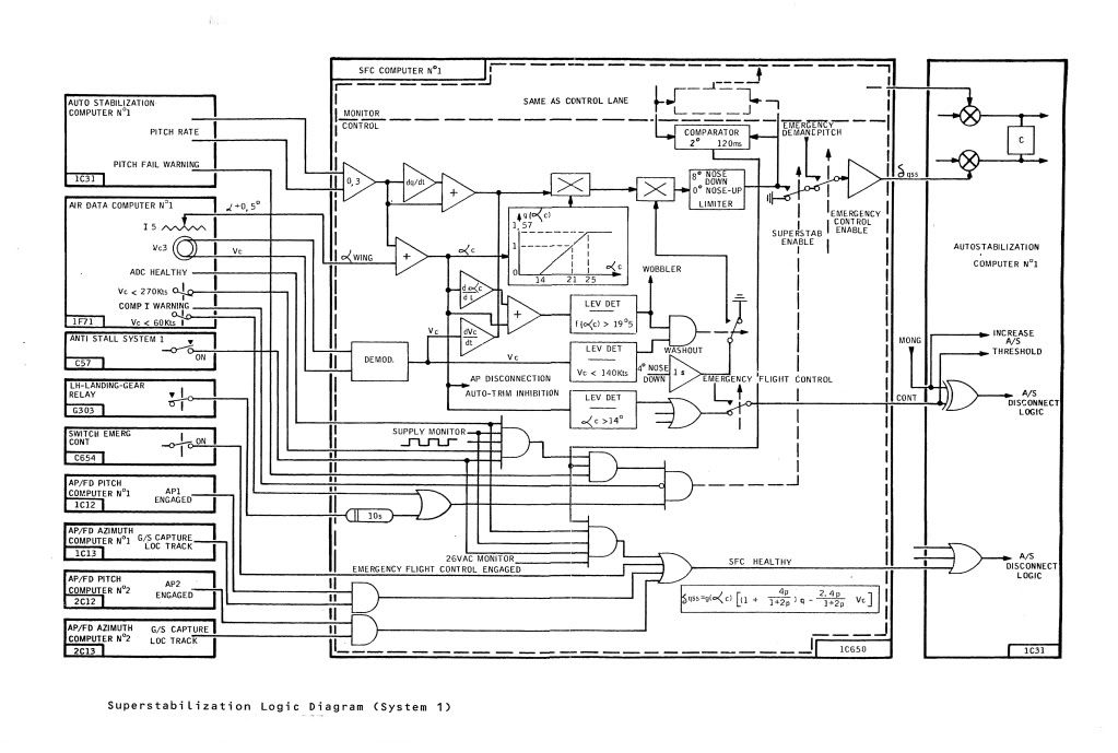
To hopefully further clarify, this was controlled from the SFC computer and was a two part mix:
1) With Vc < 270 KTS the AUTOSTAB pitch damping was increased as a function of pitch rate and pitch rate DOT, Vc DOT and corrected (wing) incidence. Maximum possible demand limited to 8\xb0 nose down.
2) With Vc < 140 KTS and alpha/alpha rate greater than 19.5\xb0 (this itself would generate the 'wobbler' or 'unmistakable warning') a 4\xb0 nose down signal is generated over a 1 second time constant.
I hope the enclosed diagram helps to put it all in place.
Best Regards
Dude
Subjects
Auto-stabilisation
Fuel Burn
Links are to this post in the relevant subject page so that this post can be seen in context.
Reply to this quoting this original post. You need to be logged in. Not available on closed threads.
December 23, 2010, 09:21:00 GMT
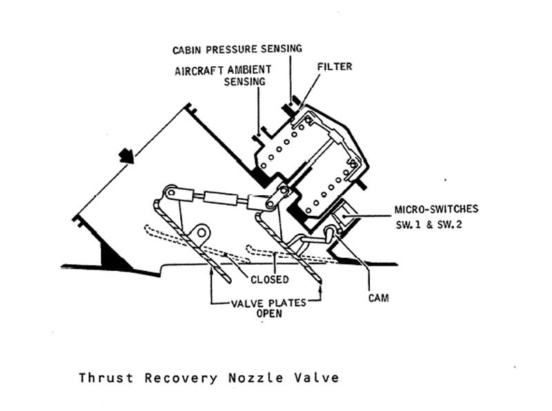
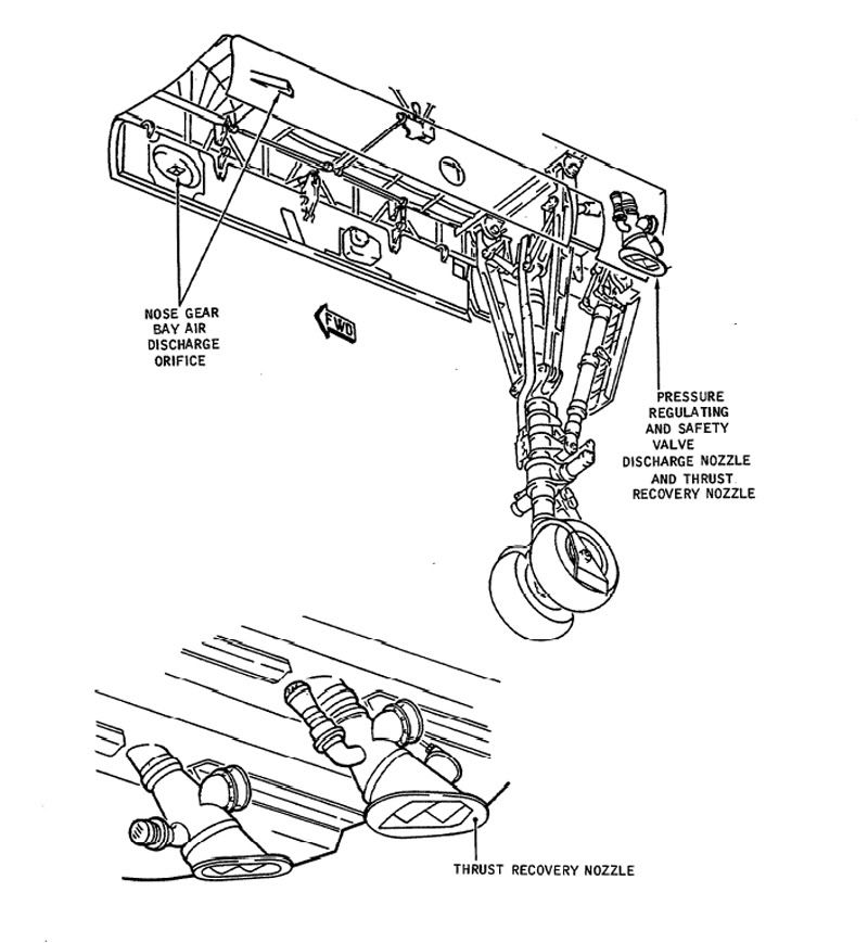
permalink Post: 6139046
Best Regards
Dude
Last edited by M2dude; 23rd December 2010 at 10:42 . Reason: I stil kant sprell
Subjects
Boeing
Nozzles
Pressurisation
Thrust Recuperator
Vortex
Links are to this post in the relevant subject page so that this post can be seen in context.
Reply to this quoting this original post. You need to be logged in. Not available on closed threads.
December 23, 2010, 11:44:00 GMT
permalink Post: 6139267
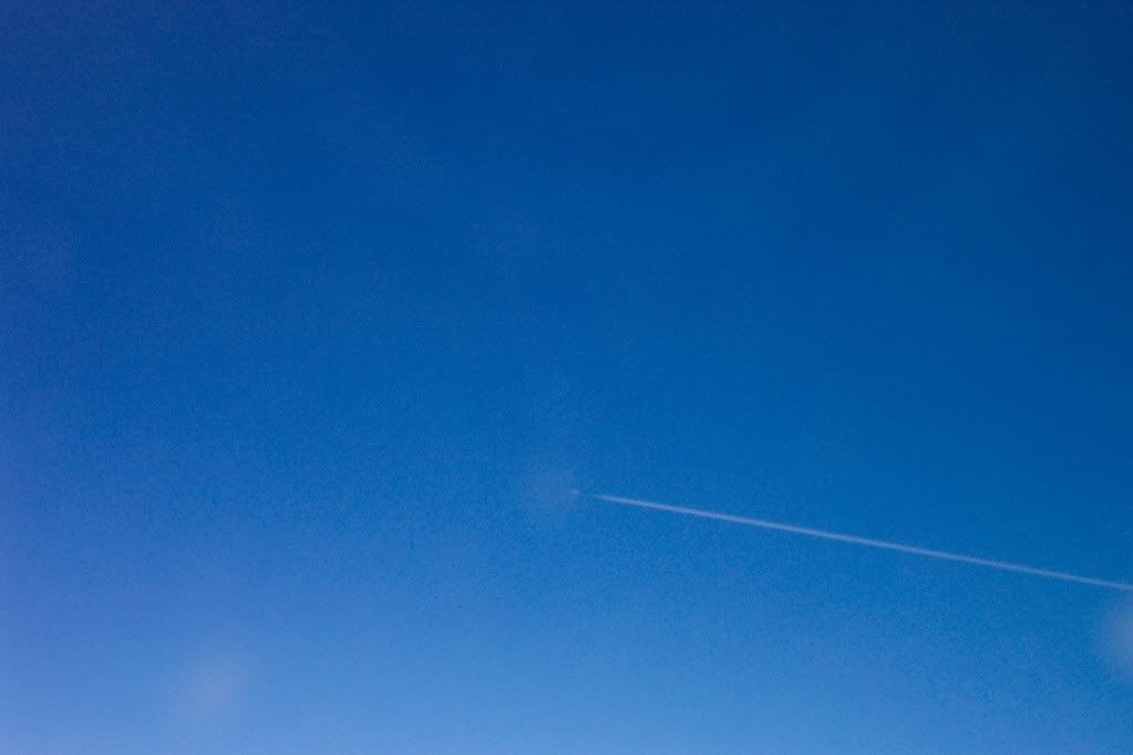
I took this one over the Atlantic, of G-BOAF, BA002 at Mach 2 FL 560 from G-BOAD FL 480 Mach 1.9 (test flight) in July 2003. (Mach 3.9 closing
).
Best rgards
Dude
Subjects
G-BOAD
G-BOAF
Links are to this post in the relevant subject page so that this post can be seen in context.
Reply to this quoting this original post. You need to be logged in. Not available on closed threads.
December 23, 2010, 19:43:00 GMT
permalink Post: 6140089
CliveL
Subjects: None
No recorded likes for this post (could be before pprune supported 'likes').Reply to this quoting this original post. You need to be logged in. Not available on closed threads.
December 23, 2010, 20:07:00 GMT
permalink Post: 6140128

Subjects: None
No recorded likes for this post (could be before pprune supported 'likes').Reply to this quoting this original post. You need to be logged in. Not available on closed threads.
December 24, 2010, 12:16:00 GMT
permalink Post: 6141238
 ).
).

Subjects: None
No recorded likes for this post (could be before pprune supported 'likes').Reply to this quoting this original post. You need to be logged in. Not available on closed threads.
December 24, 2010, 13:02:00 GMT
permalink Post: 6141291
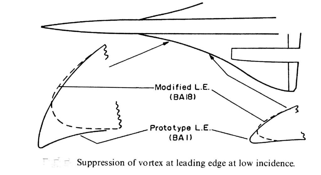 Christian asked if there was an aerodynamicist in the house - I guess that would be me!
The original question was whether there was any vortex activity in subsonic cruise, but the discussion went on to ask about designing for subsonic drag I think.
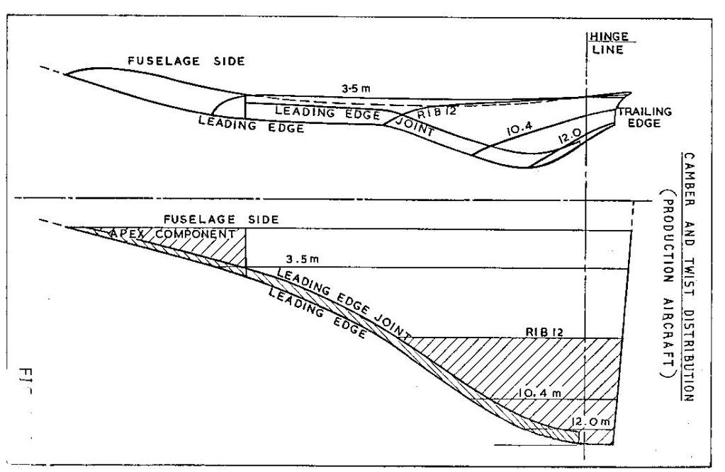
The answer to the first bit is that the vortex flow started in a gentle manner from about 6 or 7 deg AoA and got steadily stronger. Depending on the chosen cruise speed and the aircraft weight, the subsonic cruise AoA would have been in the region of 4.5 to 5 degrees, i.e. below any significant vortex development. 6/7 deg would correspond to something in the range 250 to 280 kts probably (I haven't done the sums)
What we were trying to do for subsonic cruise was to have what is known in the trade as 'leading edge suction' acting on a nice bit of forward facing area so that it tried to drag the aircraft forwards as it were. As you can see from the diagram the prototype aircraft had a much more cambered LE so that both suction and forward facing area were very reasonable. This prototype shape was nicely rounded so that LE separation and top surface vortex generation started at a higher AoA than on the production aircraft. Unfortunately this shape, which featured a rather sharp LE on the undersurface, generated a vortex on the undersurface of the wing in supersonic flight and low AoA (near zero 'g'). This vortex got into the intake and caused the engine to surge, so we had to redesign the LE ahead of the intakes as shown. This cost us a little subsonic drag, so you can see from the diagram what you need to do to keep subsonic cruise drag down.
Hope this answers the questions
CliveL
Subjects
AoA
Engine surge
Intakes
Vortex
Links are to this post in the relevant subject page so that this post can be seen in context.
Reply to this quoting this original post. You need to be logged in. Not available on closed threads.
December 24, 2010, 14:31:00 GMT
permalink Post: 6141419
Subjects: None
No recorded likes for this post (could be before pprune supported 'likes').Reply to this quoting this original post. You need to be logged in. Not available on closed threads.
December 24, 2010, 17:09:00 GMT
permalink Post: 6141672
and as you see, they show up quite clearly on Fox Bravo as well.
Judging by the page dates in the SRM, BA started it all, and Air France followed, with all the aircraft being modified by 1981. But that's just my guess.
CJ
Subjects
Air France
British Airways
Links are to this post in the relevant subject page so that this post can be seen in context.
Reply to this quoting this original post. You need to be logged in. Not available on closed threads.
December 24, 2010, 18:25:00 GMT
permalink Post: 6141781
 ">
">
Dammit! I thought I had read that [xxxxquote] gave me one of those pretty text boxes ah well, back to the drawing board.....
Unfortunately the only flow visualisation pictures I have are taken at AoAs where the tip vortex has been swallowed by the main vortex, but I thought I would paste them anyway as most people would never have seen them. In this one you can see the forebody vortices quite clearly (the bluegreen streaks) but since it is a zero sideslip case they don't go anywhere near the fin.
On closer inspection, maybe you can just see the wingtip vortices as separate bits of curly white smoke very close to each wingtip.
I'm not going to risk losing all that typing trying to attach a second picture, so I will send that separately
CliveL
Subjects
Sideslip
Vortex
Links are to this post in the relevant subject page so that this post can be seen in context.
Reply to this quoting this original post. You need to be logged in. Not available on closed threads.
December 24, 2010, 18:28:00 GMT
permalink Post: 6141784
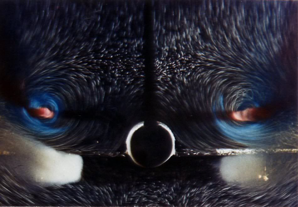
OK, here is another one .....
CliveL
Subjects: None
No recorded likes for this post (could be before pprune supported 'likes').Reply to this quoting this original post. You need to be logged in. Not available on closed threads.
December 26, 2010, 09:38:00 GMT
permalink Post: 6143531
Lets start with a comparison of the lft on a conventional subsonic wing with that of a slender wing like Concorde:
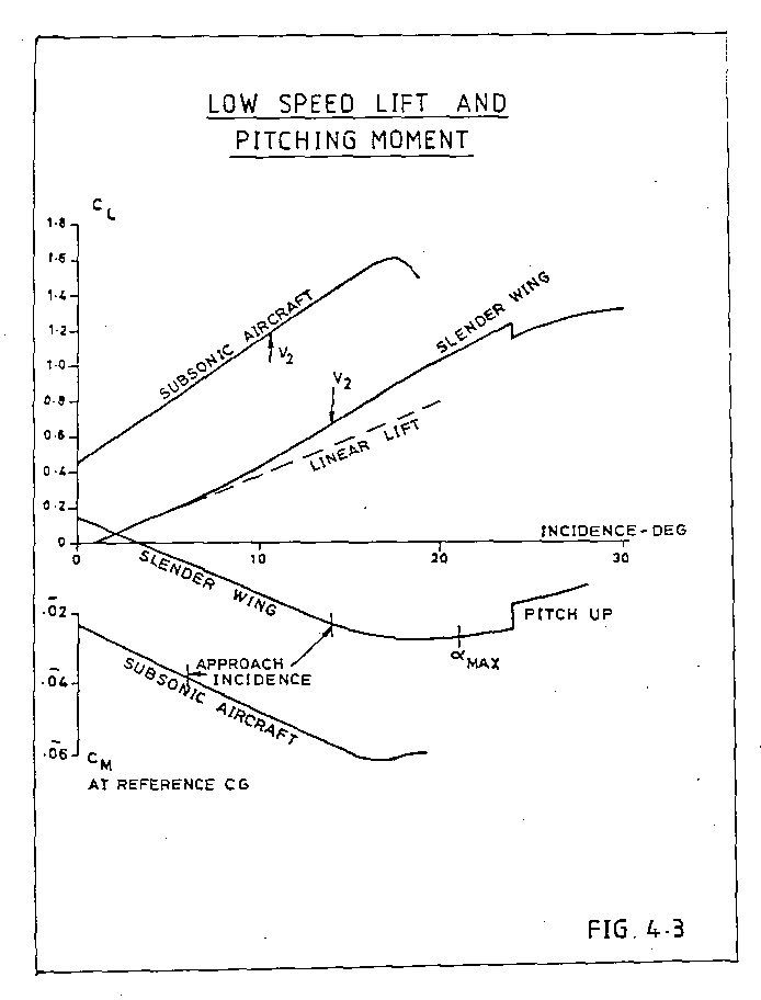
The subsonic line is linear, the slope depends on the geometry of the wing; high aspect ratio wings have a higher slope than low aspect ratio, unswept wings a higher slope than swept. Concorde, being a low aspect ratio swept wing has no chance!
To get a decent approach speed with a delta wing which has 'conventional' wing sections you need either a long U/C and work with high landing AoA or a large wing area to get the wing loading down. I would put the Avro Vulcan in the latter class. A large wing area is bad news for supersonic aircraft, but the Germans, working during WW2 found that if you give the delta sharp leading edges the flow separates at the leading edge and forms a pair of vortices that flow over the upper wing surface.
A vortex, if you could see it, is like a tornado (twister) turned on its side. The essential feature is that it is associated with low static pressures. As you get closer to the centre of the vortex the pressure drops more and more. The red zones at the centre of that transverse view are very low pressure indeed, but even the outer zones have quite low pressure.
I will have to put it up as a separate posting, but there are pictures that show that as AoA increases not only does the vortex get stronger (more suction) but the area of the wing affected by the vortex also inceases. This 'double whammy' gives the vortex a nonlinear effect. This 'nonlinear' lift is what is sometimes called 'vortex lift'.
It doesn't come for nothing - since by definition the flow is separated from the leading edge there is no alleviating 'leading edge suction' to reduce drag, and you won't go very far wrong if you take the drag of an aircraft with such a wing as Profile Drag plus Lift (times) tan AoA.
Concorde is a bit more subtle - the nose of the wing is drooped so that the flow does not separate until the AoA reaches 6 or 7 deg, giving us a good L/D in subsonic cruise whilst still having a healthy lift at approach speed.
Does this fit the bill?
CliveL
Subjects
AoA
Vortex
Links are to this post in the relevant subject page so that this post can be seen in context.
Reply to this quoting this original post. You need to be logged in. Not available on closed threads.
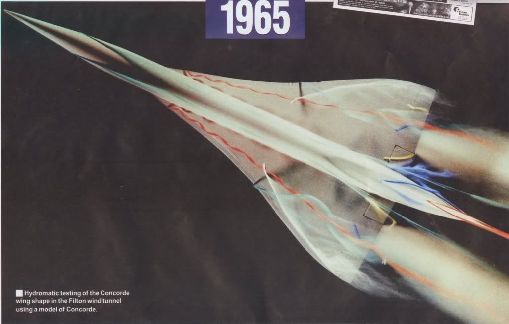
December 26, 2010, 09:51:00 GMT
permalink Post: 6143540
 Ok, second picture (can anyone tell me how to attach more than one?)
These need a bit of explaining I'm afraid. They are 'oil flow' pictures - you paint the model wing with a mixture of paraffin, engine oil and lamp black and blow air over it. The resulting pattern shows how the air is flowing (or not flowing, which is its primary purpose) over the wing surface.
I the diagram marked up in red the 'S' shaped line is a typical streamline where the air is brought down onto the surface inboard, moves downstream and across towards the tip under the combined action of fore and aft velocity and vortex rotational velocity and tis finally lifted off the surface by the vortex. the triangular zone marked out in red is the area of the wing 'scrubbed' by the vortex flow. If you compare the pictures at various AoA you will see that this area increases substantially as AoA increases.
On the21 deg picture you can also see signs of a second vortex between the main vortex and the wingtip, but this is not the classic 'tip vortex'
CliveL
Subjects
AoA
Vortex
Links are to this post in the relevant subject page so that this post can be seen in context.
Reply to this quoting this original post. You need to be logged in. Not available on closed threads.