December 26, 2010, 15:58:00 GMT
permalink Post: 6143964
Mike's earlier question had me scratching my head too, hence my question.
What are the fundamental reasons for each of the limitations, and what were the consequences of going outside them?
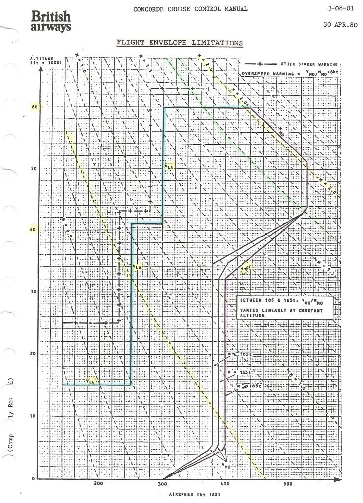
Going clockwise from the left, we have :
VLA (lowest admissible speed)
One would expect a curve for constant alpha max against IAS and altitude, not the staircase in the diagram.
Was this for simplicity of use of the diagram?
Max altitude (60,000ft)
This is the 'simplest' one: it was the highest 'safe' altitude from which an emergency descent could be made, in the case of a window blowing out, without having the blood of the pax boil....
Test flights (without pax, and with the crew pressure-breathing oxygen) did go as high as 69,000ft.
Mmo (max operating Mach number)
Mach 2.04 is usually quoted as having been chosen to assure an adequate life of the airframe.
But what effect does a higher Mach number as such have?
Or are Mmo and Tmo (127\xb0C) directly related?
Vmo (max operating speed) = 530kts until 43,000ft
I suppose this is related to structural limits (qmax)?
Vmo reducing to 380/400kts at about 33,000ft
What is the limiting factor here (other than qmax)?
Vmo constant at 380/400kts down to 5,000ft
What is the limiting factor here? The answer will no doubt also explain why this is slightly weight-dependent.
Vmo reducing to 300kts between 5,000ft and 0 ft
Why the sudden change below 5,000ft?
CJ
Subjects
Depressurisation
Flight Envelope
IAS (Indicated Air Speed)
Mmo
TMO (Temprature Max Operating)
Vmo
Links are to this post in the relevant subject page so that this post can be seen in context.
Reply to this quoting this original post. You need to be logged in. Not available on closed threads.
December 27, 2010, 10:38:00 GMT
permalink Post: 6144908
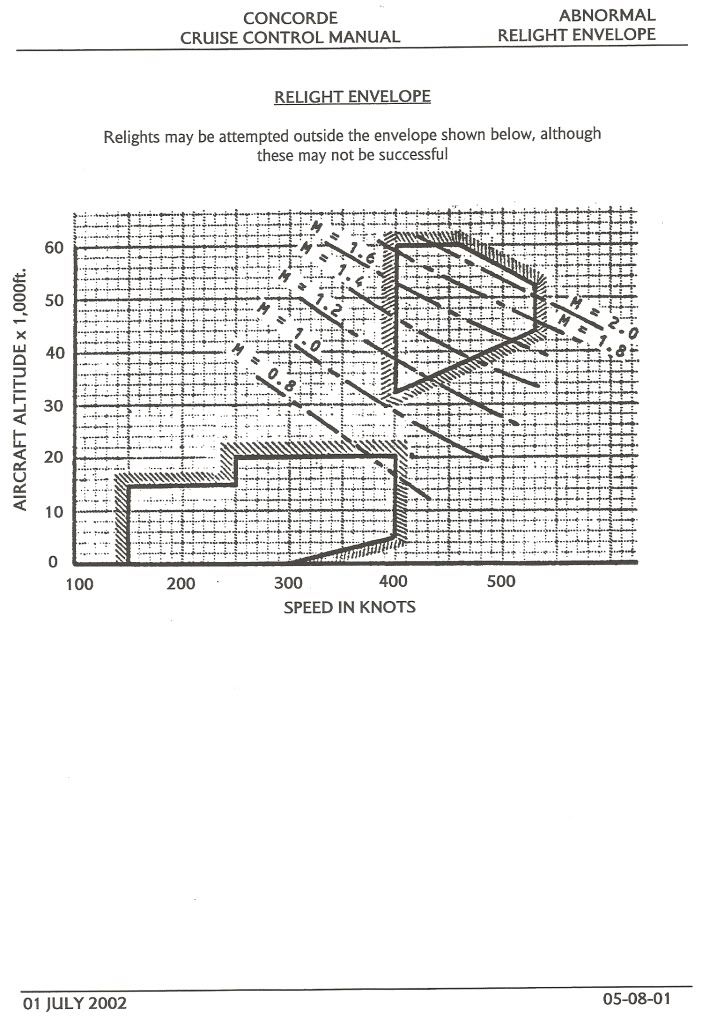
From the Cruise Control Manual:
Best Regards
Bellerophon
Subjects
Relight
Links are to this post in the relevant subject page so that this post can be seen in context.
Reply to this quoting this original post. You need to be logged in. Not available on closed threads.
December 28, 2010, 21:54:00 GMT
permalink Post: 6147254
My guess is that the upper digital counter indicates the proportion of the fuel flow that goes to the reheat but it's only a guess.
Sorry, I have no figure for the max fuel consumption.
The '35 tonnes/hr' limit on the indicator is obviously beyond the upper limit, like the speedo on a car.....
But yes, fuel consumption at takeoff with reheat was horrendous, and would have emptied all the tanks in an hour or less.
CJ
Subjects
Afterburner/Re-heat
Fuel Burn
Haynes guide to Concorde
Links are to this post in the relevant subject page so that this post can be seen in context.
Reply to this quoting this original post. You need to be logged in. Not available on closed threads.
December 29, 2010, 03:57:00 GMT
permalink Post: 6147577
...I have been a Concorde fan since I won a flight on it in 1980...
Lucky devil! I'm glad you enjoyed the flight.
...There appears to be two digital displays per gauge as well as an analogue display...
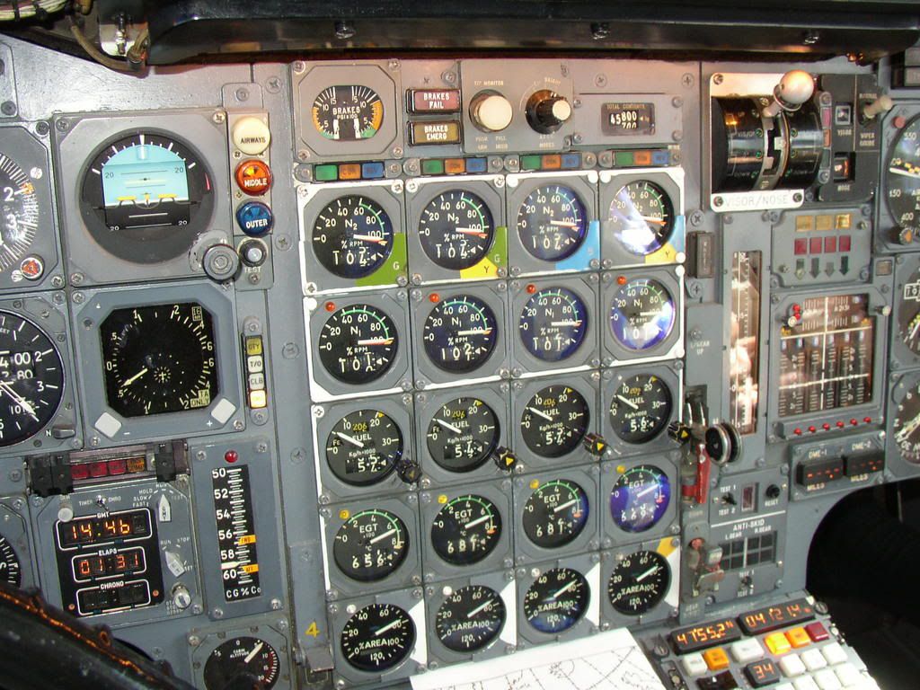
Only the lower digital counter was actually a display, and was a digital repeater of the total fuel flow information being displayed by the pointer on the dial. The upper digital counter was merely a digital indication of the value to which the internal yellow triangular bug had been set by the F/E using the bug setting knob on the lower right of the gauge.
Very briefly, during the pre-flight set up, the F/E would calculated the expected fuel flows for each engine, during the take-off whilst using re-heats. He would set this on the bug, and this achieved two things.
Firstly, it gave him a good visual indication whether the required fuel flows were being achieved. Too low a fuel flow would indicate a re-heat problem on that engine.
Secondly, it programmed the expected fuel flow into the engine take-off monitor, as this was one of the parameters that had to be satisfied in order for the monitor to illuminate the Green \x93Clear-to-Go\x94 light.
The Green \x93Clear-to-Go\x94 light was one of three \x93Power Management\x94 lights immediately above the N2 gauge for each engine, the other two being an Amber \x93Configuration\x94 light and a Blue \x93Reverse\x94 light. Some take-offs would require all four Green lights to be on, other take-offs, depending on ambient conditions, aircraft weight and runway length, might only require three Green lights.
...What was the peak consumption per engine, and why two digital displays on each gauge?...
The maximum peak consumption predicted was 21,700 kg/eng/hr, or 86,800 kg/hr total. This would have been predicted for a re-heated take-off, at +8\xb0C, at an elevation of -1,000 PA.
More typically, on a standard day, at a sea level airfield, 20,700 kg/eng/hr, or 82,800 kg/hr total. You can probably see why we turned the re-heats off fairly quickly!
...accelerating to Mach 2.0 and immediately slowing down again....we only went to 43,000 feet so the sky did not get very dark...
43,000 ft is actually a bit too low for Concorde to be at M2.0, as you may see from this graph of her Flight Envelope. She would have been limited to around 525 kts / M1.7 at that height, so I suspect you may have been a little higher than you remember, possibly somewhere around 53,000 ft.
Happy New Year
Bellerophon
Subjects
Afterburner/Re-heat
Flight Envelope
Fuel Burn
Links are to this post in the relevant subject page so that this post can be seen in context.
Reply to this quoting this original post. You need to be logged in. Not available on closed threads.
December 30, 2010, 09:50:00 GMT
permalink Post: 6149785
In response to both Christiaan and Brit312 posts, here is the role of honour proudly on display inside G-BOAC at Manchester.

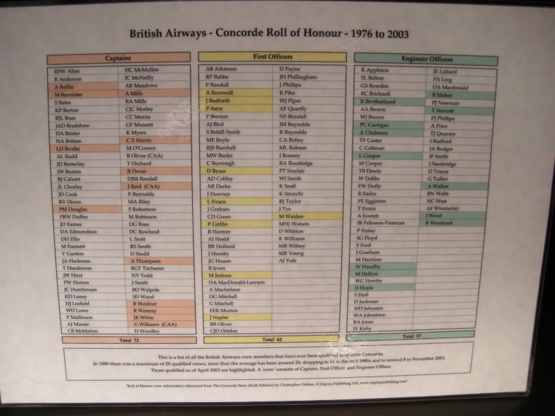
Regards
Andy
Subjects
Captains
G-BOAC
Links are to this post in the relevant subject page so that this post can be seen in context.
Reply to this quoting this original post. You need to be logged in. Not available on closed threads.
January 02, 2011, 15:11:00 GMT
permalink Post: 6155142
Looking through my 'archive', I've finally found this photo again... been looking for it for ages.
Kinky .... !!
Found on the net a few years ago. It's either 002 (G-BSST) or 01 (G-AXDN) at Fairford.
All Concordes have this 'kink', but the interesting thing is, that it's only visible from one very precise spot in line with with the wing leading edge. A few metres to the left or right, or forward or back, and the 'kink' disappears.
Many people are not even aware it exists.
Happy 2011 to all !
CJ
Subjects
Fairford
G-AXDN
Links are to this post in the relevant subject page so that this post can be seen in context.
Reply to this quoting this original post. You need to be logged in. Not available on closed threads.
January 02, 2011, 16:17:00 GMT
permalink Post: 6155241
And of course a happy 2011 to all!
CliveL
Last edited by CliveL; 2nd January 2011 at 16:25 . Reason: Additional information
Subjects
Intakes
Links are to this post in the relevant subject page so that this post can be seen in context.
Reply to this quoting this original post. You need to be logged in. Not available on closed threads.
January 02, 2011, 21:17:00 GMT
permalink Post: 6155651
It's always fun doing a bit of 'aero-archaeology'.... isn't it?
You're both right.
At the roll-out, 01 was already marked "AEROSPATIALE", and the tracking camera 'target' was already painted on the right-hand side (but not on the left!).
So the earlier photo in question is definitely 002.
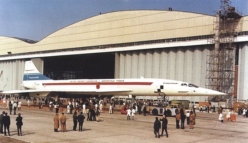
I recently re-scanned my ancient 'Filton' photos... only black-and-white, but maybe worth adding them to the 'records'.
G-AXDN being moved out of the hangar.
Interestingly, no tracking camera target on the left-hand side.... it must have been added very soon after, because I have a photo from a few weeks later, where it's in place on both sides.
Roll-out or not, G-AXDN still wasn't quite finished... three of the four engine nozzles/thrust reversers are still missing and replaced provisionally by 'space frames'.
This one again confirms the "AEROSPATIALE" marking. Also, somebody hadn't gotten round to painting the tail cone yet....
CJ
Oh, and a PS....
Another 'kinky' photo, this one of 001 when still outside the Le Bourget museum.

(Photo from the ConcordeSST.com site).
Subjects
Filton
G-AXDN
Le Bourget
Links are to this post in the relevant subject page so that this post can be seen in context.
Reply to this quoting this original post. You need to be logged in. Not available on closed threads.
January 02, 2011, 23:21:00 GMT
permalink Post: 6155838
I should have kept a diary... never did.
According to the ConcordeSST site, the roll-out was on 20 September 1971, but (according to various internet items) Aerospatiale was already formed in 1970.
Looking at the general mess, the photo you mention (see below) was several weeks, if not a few months, before the roll-out.
Look closely.. I would say even the leading edges are not in place yet.

CJ
Subjects
Aerospatiale
Links are to this post in the relevant subject page so that this post can be seen in context.
Reply to this quoting this original post. You need to be logged in. Not available on closed threads.
January 12, 2011, 20:45:00 GMT
permalink Post: 6175826
Here's a picture I took as the aircraft turne left towards the French coast:

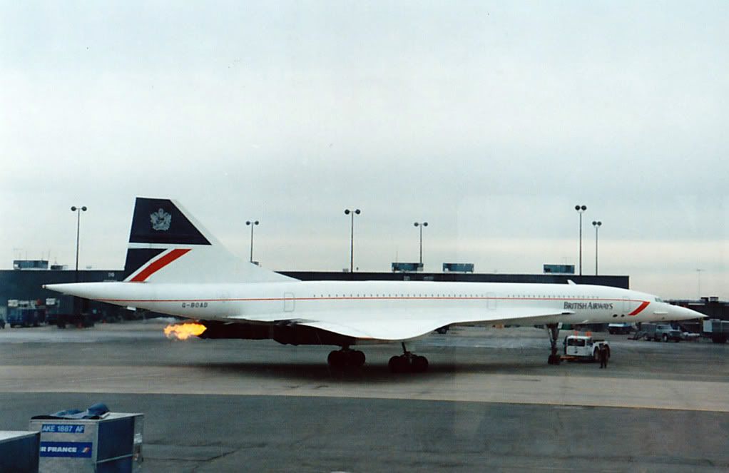
One memory is climbing through 50,000 feet over South Wales before turning down the Bristol Channel. It was glorious August day and I had a great view forward past the captain and particularly out of the left window. The speed over the ground at Mach 0.95 seemed noticably faster than a subsonic jet, and that view was breathtaking! The Bristol Channel was edged in golden yellow beaches, and I could see right across south west England to the English Channel. In my headset the controller called another aircraft; "Speedbird 123 if you look up now you will see you are about to be overflown by Concorde". I leaned towards my side window and there was Speedbird 123, a tiny scurrying beetle miles below us. From this height the fair-weather cu looked as if they were on the ground - like small white splodges from some celestial artist's paint brush.
We cruised at Mach 2 and 60,000' over the Bay for a while and the pax came forward to view the flightdeck. I was amazed how patient was the supernumery captain who was answering the same questions over and over again was (the flight crew were too busy to chat).
The approach to CDG looked far steeper than other airliner approaches I had witnessed from the flight deck; more like one of my glide approaches in the Chipmunk! But it wasn't, of course, as we were following the 3 degree glideslope. I guess it was an illusion brought about by the steep pitch angle.
I remember the captain resting his hands on the throttles as they shuttled back and forth under autothrottle control, the smooth touchdown, the 'landing' of the nosewheel followed by full forward stick, and thinking "we'll never make that turn off". Then on came the powerful reverse and the brakes, I was thrust foreward in my harness, the speed disappeared, and we made the turnoff easily!
Oh, and that stange bouncy ride in the flight deck on the ground as the long nose forward of the nosewheel flexed over every joint in the taxyway. So bad at times it was difficult to take a photograph!
What an experience!
I have a question which I hope hasn't been answered in the pages (20 to this one) that I've yet to read.
From an earlier post I understand that the anti-skid used a rotational reference from the unbraked nosewheels to compare to the rotation of the mains, and that with gear down in the air a substiute nose-wheel referance is supplied which, because the mains are not yet rotating, allows the anti-skid to keep the brakes off.
But what happens when the mains touch down with the nosewheels still high in the air? What (if anything) inhibits wheel braking until the nosewhels are on the ground (and therefore rotating)?
Also, this thread started with a question about the lack of an APU. When Concorde was parked could the aircon and cabin lighting be powered by external electrical power, or did the cabin aircon without engine power require an external 'aircon unit' to be connected? Or was aircon simply not available without at least one engine running?
And one for Landlady or any other CC. If a table top was set up between the cabins during service, how did the 'front' crew service the first 2 rows of the rear cabin?
Being 'up front' for my entire flight, I missed out on the cabin service. But superb though I'm sure that was, under the circumstances it's not something I regret!

Last edited by Shaggy Sheep Driver; 12th January 2011 at 22:07 .
Subjects
APU (Auxiliary Power Unit)
Anti-skid
Auto-throttle
Braking
CDG
Cabin Crew
Captains
G-BOAD
Glide
Landing Gear
Round the Bay
Links are to this post in the relevant subject page so that this post can be seen in context.
Reply to this quoting this original post. You need to be logged in. Not available on closed threads.
January 13, 2011, 11:10:00 GMT
permalink Post: 6176851
On C of A renewal test flights (what I always called the 'fun flights') we DID used to do a 'flat' acceleration to Mach 2.1 quite regularly, as part of the test regime, and the aircraft used to take things in her stride beautifully. (And the intakes themselves were totally un-phased by the zero G pushover that we did at FL630)
As usual Dude you beat me to it! I really must give up having another life

As Dude says, the 'cruise' condition was set by the aircraft specification for transatlantic range on an 85% (ISA +5) day and the chosen mach Number was 2.0 (of which more anon). This gives a Total Temperature of 400.1 deg K. [Dude, I know your pipe-smoking thermodynamicist and he was having you on - he is quite capable of memorising the square/square root of 407.6 or whatever!]
To give margins for sudden changes in ambient temperature (we had to cater for a 21 deg change in one mile) the Mmo was set at 2.04 which matches 400 degK at ISA +1. In theory then we could have flown faster than our chose Mmo at anything colder than this, but there are two limits:
1) The object is not to fly as fast as you can but to fly with minimum miles/gallon. If you have a nice cold day and enough thrust to go either faster or higher which do you choose? For best specific range you go higher every time.
2) The thing that everyone forgets is that civil aircraft have to have margins around their authorised envelope. In Concorde's case these were set principally by the intake limits and engine surge.
Dude also says quite correctly that 101 flew to 2.23M but the production aircraft was limited to 2.13M. Now you may not believe this, but 101 could fly faster than the production aircraft because she (101) leaked like a sieve!.
I doubt I will get away with that without some explanation

Once you get past a certain Mach Number the airflow into the intake is fixed. The performance (intake pressure recovery and engine face flow distortion) then depends on how this air is shared between the engine and the throat 'bleed'. This bleed was ducted over the engine as cooling air and then exhausted (in principle) throught the annulus formed between the expanding primary jet and the fixed walls of the con-di nozzle. But if you took, or tried to take, more bleed air the intake pressure recovery went up and the primary jet pipe pressure went up with it. This meant that the primary jet expanded more and squeezed the available annulus area which restricted the amount of bleed air one could take.
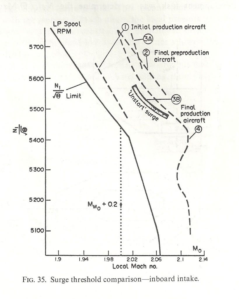
Obviously if there are alternative exit paths between intake and final nozzle then you can take more bleed air off and the engine face flow distortions will benefit along with the surge margin. 101 was fairly 'leaky' in this respect, particularly around the thrust reverser buckets on the original nozzle design. This meant that 101's intake distortions were lower than the production aircraft so she could fly faster without surge - at least with the first attempt at intake control 'laws'. We managed to tweak most of the margin back eventually. Engine bay leaks were good for surge margin but VERY bad news for m.p.g.!
Here are a couple of diagrams to show what I mean. the first shows the surge lines for the various aircraft variants and also the N1 limiter Dude was talking about. NB: the X-axis is LOCAL Mach Number not freestream. The difference comes from the compression of the underwing flow by the bit of the wing ahead of the intake. Mmo + 0.2 is shown
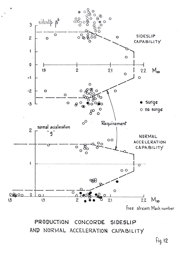
 ">The next shows the surge free boundaries in sideslip and normal acceleration. You can see the zero 'g' capability Dude was enthusing over.
 ">
">
As for 'high speed stall', I don't think we ever contemplated trying it! Our requirements in 'g' capability were defined and that was it. Besides, the aircraft would fly like the proverbial stone-built outbuilding at those sorts of conditions so I don't think one would have been able to get anywhere near a stall in the conventional sense. Stall as commonly defined for subsonics (deterrent buffet) might have been another matter, but I don't remember anything.
Cheers
Last edited by CliveL; 13th January 2011 at 11:17 . Reason: additional explanation
Subjects
AICU (Air Intake Control Computer)
Bleed Air
Engine surge
FL600
Fatigue
Intakes
Mmo
N1 (revolutions)
Nozzles
Sideslip
TMO (Temprature Max Operating)
Thrust Reversers
Links are to this post in the relevant subject page so that this post can be seen in context.
Reply to this quoting this original post. You need to be logged in. Not available on closed threads.
January 13, 2011, 20:23:00 GMT
permalink Post: 6177940

From the angle the 'kinky' photo was taken the outer sweep of the ogee wing is towards the camera before sweeping aft to the drooped and washed-out tips and it looks like a kink in the LE sweep. The actual shape is seen better in the picture above. I've spent hours studying our G-BOAC at Manchester and to me the wing is a complex and lovely blend of curves and slopes, with no sudden changes such as a kink would require. Standing under the wing and observing it closely, no kink is apparent.
The wash-out on the tips shows particularly well in the above photo (washout is a forward twist of the wing at the tips to reduce the angle of attack of the tips compared to the rest of the wing, to prevent tip-stalling).
A question I have, relating to the photo above, is about the LE. The LE definately 'droops' in the area ahead of the intakes (it doesn't do so nearer the roots or tips). Is this to provoke a clean flow-breakaway in this area at high angles of attack to encourage the votices to form at this point as the wing transitions to vortex lift?
M2Dude Thanks for the kind words and careful explanations. I take it from your description of the anti-skid that once the mains start to rotate the brakes can be used, as the anti-skid comes 'off' (mains no longer think they are skidding).
I thought there was protection to prevent brake use until the nose wheels have landed, else brake application with the nose high would cause a rapid nose-down pitch, slamming the nosewheels on! Is there any such protection?
Last edited by Shaggy Sheep Driver; 13th January 2011 at 21:41 .
Subjects
Anti-skid
Braking
G-BOAC
Intakes
Vortex
Links are to this post in the relevant subject page so that this post can be seen in context.
Reply to this quoting this original post. You need to be logged in. Not available on closed threads.
January 14, 2011, 08:00:00 GMT
permalink Post: 6178815
 )
)
Best regards
Dude

Subjects: None
No recorded likes for this post (could be before pprune supported 'likes').Reply to this quoting this original post. You need to be logged in. Not available on closed threads.
January 14, 2011, 08:29:00 GMT
permalink Post: 6178845
The prototype had even more 'droop' in front of the intakes, but that produced a vortex at low incidence (near zero 'g') that went down the intakes and provoked surge.
Cheers
Clive
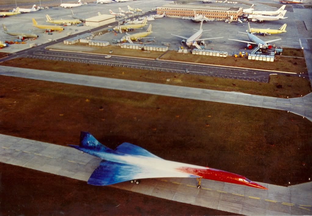
PS: Everyone seems to be adding their favourite Concorde photograph so I thought I would be different and add my LEAST favourite
 ">
">
Last edited by CliveL; 14th January 2011 at 08:43 . Reason: adding a photo and additional remarks
Subjects
C of G
Engine surge
Intakes
Trim
Vortex
Links are to this post in the relevant subject page so that this post can be seen in context.
Reply to this quoting this original post. You need to be logged in. Not available on closed threads.
January 15, 2011, 08:20:00 GMT
permalink Post: 6180678
I personally agree about that photo, YUCH!!

Now about the cabin pressure thing: The pressurisation system would control to a MAXIMUM differential of 10.7 PSIG. Now at 60,000' the static pressure is 1.04 PSIA and at that altitude we would not QUITE be able to hold a cabin altitude of 6000', more like 6,200-6,300'. This is because 6000' altitude corresponds to a static pressure of 11.78 PSIA, giving us a diff' of 10.76 PSIG. Still as near as dammit mind, and for the MAJORITY of Atlantic crossings 6000' was fine. Such a 'civilised' cabin pressure was just one of the 1000 reasons that you never 'felt' as if you'd just flown over 3000 miles in Concorde.
Here is a diagram of the pressurisation panel.
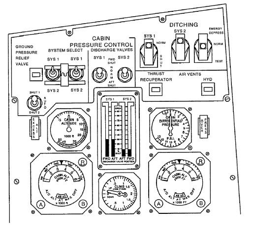
The idea was that you selected a desired cabin altitude and the system would control to maintain that altitude all the way up to max diff. You could control the rate of presurisation too, to minimise popping ears etc. (Personally I always found Concorde particualarly good in that respect). There is one minor goof in the diagram, in that the discharge valve position indicator show both systems in operation. You only ever had one of the two systems in operation (via the SYS1/SYS2 selector switches). The only exception to this was on the ground when both systems were powered (and both sets of valves fully open).
Best regards
Dude
Last edited by M2dude; 15th January 2011 at 08:31 . Reason: kerrektions
Subjects
Pressurisation
Links are to this post in the relevant subject page so that this post can be seen in context.
Reply to this quoting this original post. You need to be logged in. Not available on closed threads.
January 15, 2011, 10:59:00 GMT
permalink Post: 6180912
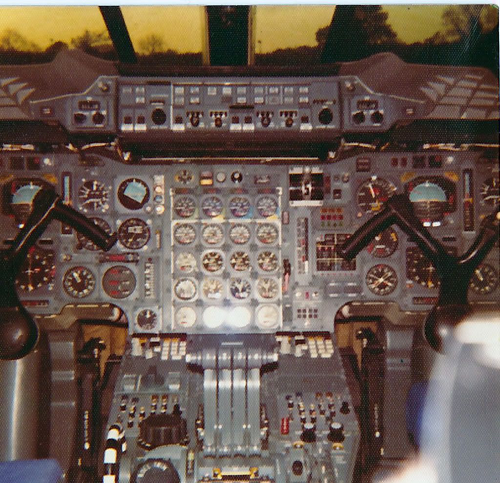
The first thing I know EXWOK and BELLEROPHON will (maybe) notice is that originally OAD had a 'normal colour' electroluminescent light plate on the visor indication panel. (If I remember rightly (it was a million years ago chaps) when this one 'stopped lighting' we could not get a replacement and had to rob 202 (G-BBDG) at Filton; this one being the same black development aircraft colour that OAD has to this day.
The OTHER first thing that you may notice is the Triple Temperature Indicator on the captains dash panel. (The first officer had his in in similar position). These got moved around (twice in the end) when TCAS was installed in the mid-90's. It was amazing just how much equipment got moved around over the years, in order to 'shoe-horn in' various bits of extra equimpent.
The cabin altimeter here fitted just above the #1 INS CDU also got moved (to the centre consul) when the FAA 'Branniff' modifications were embodied later in the 70's. It's spot got occupied by a standy altimeter mandated by the FAA but this was removed after Branniff ceased flying Concorde; the cabin altimeter returning to it's former home. The REALLY observant will notice that there is neither an Autoland Ca3/Cat2 identifier on the AFCS panel (glued on by BA at LHR) or the famous and precision built 'Reheat Capabilty Indicator' flip down plate fitted to the centre dash panel a few years later by BA.
Also not shown here, as they were buyer furnished equipment also fitted at on delivery LHR, are the two ADEUs (Automatic Data Entry Units, or INS Card readers). These were located immediatel aft of the CDU's and were used for bulk waypoint loading ('bulk' being 9, the most that the poor old Delco INU memory could handle). These were removed in the mid 90's when the Navigation Database was fitted to Concorde INUs, and bulk loading then was achieved by simply tapping in a 2 digit code. (Hardly the elegence of FMS, but still very elegent in comparison with the ADEU's, and worked superbly). A little note about these ADEU things; You inserted this rather large optically read paper data card into the thing and the motor would suck the unsuspecting card in. As often as not the ADEU would chew the card up and spit the remnants out, without reading any data, or not even bother spitting out the remnants at all. Removing these things FINALLY when the INUs were modified was absolute joy!!
ps. When G-BOAG (then G-BFKW) was delivered in 1980 it had neither any of the Branniff mods or ADEUs fitted. (Also the INS was not wired for DME updating). This meant that obviously she could not fly IAD-DFW with Branniff but also she could not do LHR-BAH either, because of the lack ADEUs. (You could not manually insert waypoints quick enough over the 'Med', or so the guys told me. So for the first few years good old FKW/OAG just used to plod between LHR and JFK. And plod she did, superbly. She never did get the ADEUs (not necessary thank goodness when the INUs got modified) but we wired in DME updating and so she could navigate around with the best of them.
My gosh I do prattle on, sorry guys.
Best regards
Dude
PS Welcome back Landlady, hope you've recovered from your fall XXXX
Last edited by M2dude; 15th January 2011 at 11:29 .
Subjects
AFCS (Automtic Flight Control System)
Afterburner/Re-heat
Auto-land
British Airways
Cabin Crew
Captains
Fairford
Filton
G-BBDG
G-BFKW
G-BOAD
G-BOAG
INS (Inertial Navigation System)
JFK
LHR
LHR-JFK Route
Visor
Links are to this post in the relevant subject page so that this post can be seen in context.
Reply to this quoting this original post. You need to be logged in. Not available on closed threads.
January 16, 2011, 06:52:00 GMT
permalink Post: 6182434

In mechanical back-up control demands were fed to relay jacks which acted as force amplifiers so the pilot was unaware of control run friction. The autopilot also fed into these relay jacks. This meant that the control precision and ability to harmonise control forces given by the electrical control system was not degraded by mechanical system shortcomings.
In electrical signalling there was a dead space at the Powered Flying Control Units (PFCU) to allow for the difference between mechanical and electrical commands produced by autostabiliser activity. Variation of this dead space with flight condition gave the autostabiliser authority limits. Autostab. was not available in mechanical signalling when the PFCU servo valve was locked to the mechanical control system.
So the control column movements were never 'ignored' by either system, but the mechanical system never 'saw' the autostabiliser commands.
Cheers
Clive
Subjects
Auto-pilot
Auto-stabilisation
PFCU (Powered Flying Control Units)
Links are to this post in the relevant subject page so that this post can be seen in context.
Reply to this quoting this original post. You need to be logged in. Not available on closed threads.
January 16, 2011, 09:41:00 GMT
permalink Post: 6182606
Hi again my friend. To further expand on CliveJ's superb explanation: Mechanical control inputs were fed to each of the 8 Powerd Flying Control Units (PFCUs), but in electronic signalling (either Blue or Green) these inputs were de-clutched at the PFCU input lever. When Fly By Wire' signalling is not available, the mechanical inputs (which as CliveL quite rightly points out) are driven by the Relay Jacks, now are locked to the input lever and can now move the input jack of the PFCU (known as the spool valve) and subsequently cause the PFCU to drive the control surface. (The body of the PFCU moved, the main jacks were attached at each end to structure and so obviously did not move). Hopefully this diagram will help visualising the process a little easier:
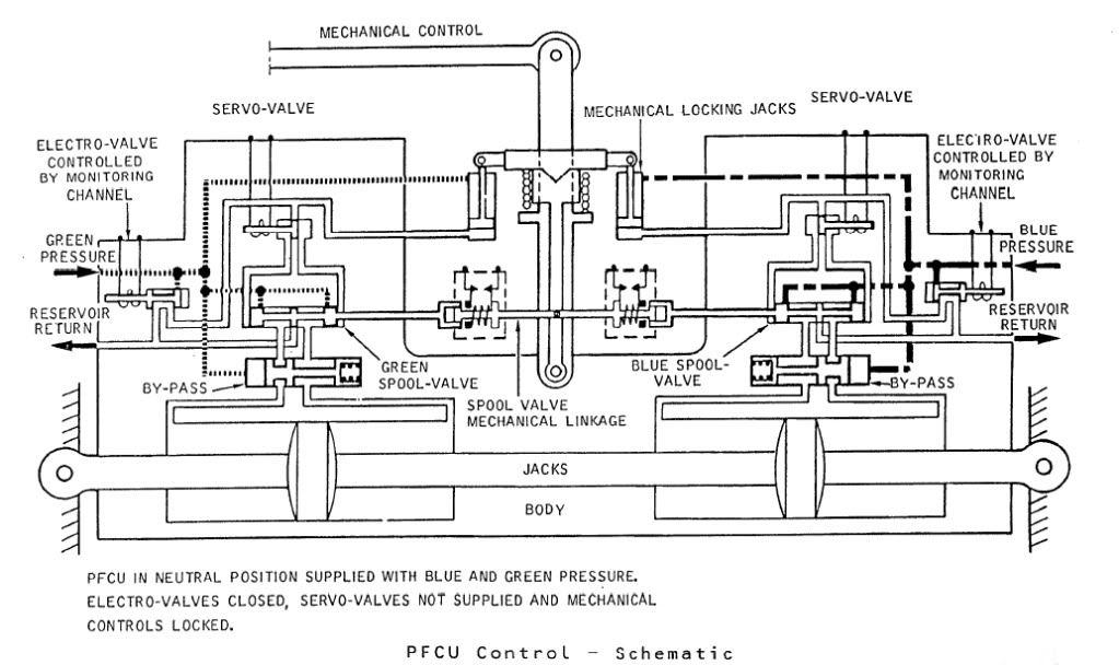
The diagram shows Green & Blue hydraulics supplied but the electro-valves (opened by the respective FBW channel) are both closed. You can see that the mechanical input lever is 'locked' to the PFCU input lever which will drive the SPOOL VALVE directly. When FBW is enabled, either the Blue or Green (never both together) ELECTRO-VALVE are signalled open, the ensuing hydraulic pressure then pushing the input clutch upwards and disengaging the mechanical input. FBW demands are now fed to the respective SERVO VALVE which will hydraulically send the SPOOL VALVE in the desired direction.
The Relay Jacks could be considered to be a little like a PFCU (you had 2 RJs per axix) but instead of the servo valves being driven by the FBW system they were driven by the autopilot and instead of driving a control surface, they drove the control runs. In manual flight the input spool was driven via a mechanical input lever, which would drive the RJ spool a little like Mech' signalling drove the PFCU spool. In A/P mode the mechanical input rod was de-clutched \xe0 la PFCU, but (and here's the clever part) this input was locked to the body of the Relay Jack which when it moved, drove the pilot's control in sympathy. (Control column, yoke or rudder pradals). As the respective control(s) was moved by the Relay Jack, the corresponding FBW position sensor (resolver) would change position and generate the FBW demand. (As the surface moved there was a feedback resolver at PFCU level).
As far as the FBW channels themselves went; there were 2 electronic signalling modes, Blue and Green, sub-divided into 3 groups (Inner Elevons, Outer & Mid Elevons and Rudders). Each group was independently monitored, and a fault in say the Rudder channel alone, would result in the rudders ONLY changing lanes. NOW ( ), The normal control channel was BLUE, and if this failed you would drop the respective channel into GREEN and if this failed you would drop into MECH. The selector switches (1 per group) enabled you to select BLUE/GREEN/MECH in that order. If for some reason you were selected to GREEN, a failure of that signalling lane would not drop you 'up' into BLUE, but into MECH. Your switch would only be in this position if you'd had a problem with BLUE, however you would select this on pushback while you were testing the flying controls, otherwise you spent your whole life selected to BLUE. As far as BA went, I can never remember a time personally when all 3 groups dropped from BLUE to MECH, but very rarely you might get a fault that caused a single group to briefly drop to MECH. Just about one of the very few common mode failures to each of the 3 groups would be a failure of the respective FBW static inverter. This thing, which was rightly monitored up to the hilt, produced a 26 Volt 1800 Hz output. (1800 Hz was chosen as this is not a harmonic of aircraft mainline 400 Hz AC supply)
Best regards
Dude
Last edited by M2dude; 16th January 2011 at 12:10 . Reason: Clarity; Oh for clarity
Subjects
Auto-pilot
British Airways
Elevons
FBW (Fly By Wire)
Hydraulic
Hydraulic System - BLUE
Hydraulic System - GREEN
PFCU (Powered Flying Control Units)
Rudder
Links are to this post in the relevant subject page so that this post can be seen in context.
Reply to this quoting this original post. You need to be logged in. Not available on closed threads.
January 18, 2011, 07:50:00 GMT
permalink Post: 6186441
I spent a lot of time on this in the 80s, but really one has to assume that Sir Lancelot put the Philosopher's Stone in the Holy Grail and buried it under the (other) end of Finnegan's rainbow and that YOU KNOW WHERE TO DIG!
When I left it the project looked a lot like this photograph that Christiaan found and posted on another site:

About 200 PAX, area ruled fuselage, new wing planform, flaps maybe, canard/foreplane, new shorter/lighter intake design,separate nacelles, new materials (probably not composites), digital avionics etc. but most of all a revolutionary new engine concept that nobody has invented yet. This engine has to produce lots of quiet thrust for airfield operation (low specific thrust) and lots of thrust with low frontal area for cruise (high specific thrust). Any takers?
Cheers
CL
Subjects
Avionics
Intakes
Links are to this post in the relevant subject page so that this post can be seen in context.
Reply to this quoting this original post. You need to be logged in. Not available on closed threads.
January 18, 2011, 16:18:00 GMT
permalink Post: 6187258
Thank you for your reply, what you describe is absolutely fascinating; It seems that composites may not be the panacea for all aircraft structural problems after all. I confess. I'm afraid that I did intentially use that awful pun (sorry
).
Regarding strucural materials, I remember reading what Ted Talbot wrote in the manuscript for his brilliant work 'Mach 2 and Bit' (not sure if he ever did get it published) when he spoke about the Bristol 188. He said something like 'the never to be repeated experiment of making an aircraft structure out of stainless steel'. One can only imagine the manufaturing problems that Brisol must have had with that one. (I seem to remember that the strucure was welded and not rivetted together
 ).
).
Yes the US now has a supercruise aircraft (the F-22 Raptor) but not of course for up to 3 hours of up to 400\xb0K either. (Although a truly superb aircraft nonetheless). And as you say, military structural material airworthiness standards in no way apply to a civil project.
I can only imagine what the original Bristol (for the Type 223?) mixing unit you described must have looked like. The Concorde unit certainly dominated the whole underfloor picture in quite a sizeable area down the back; here's a diagram of the beasty:
For all it's complexity however I can never recollect any problems occuring there.
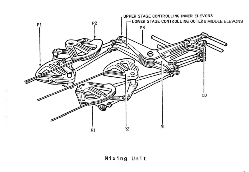
It looked far more intimidating in the flesh under the floor however.
Best regards
Dude
Subjects
Super-cruise
Links are to this post in the relevant subject page so that this post can be seen in context.
Reply to this quoting this original post. You need to be logged in. Not available on closed threads.