January 18, 2011, 20:53:00 GMT
permalink Post: 6187706
 . Here is the one of the 'forward' pages from 'The Concorde Air Intake Control System' publication: (Issue 3 Feb' 2001). There just might be a name or two there that rings a bell.
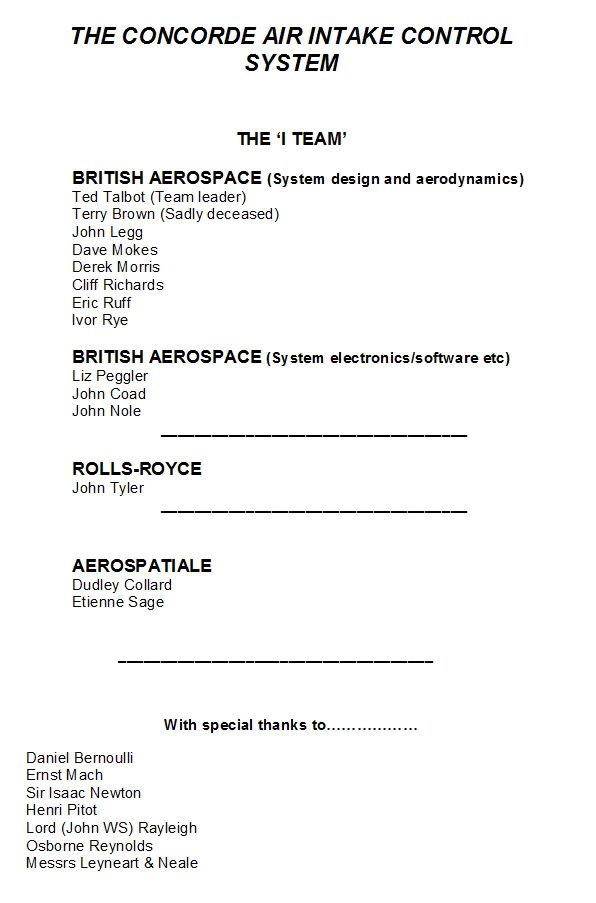
So much was achieved by such a very small team of people. An achievement that was absolutely pivotal to the successful development of Concorde.
With total respect
Dude

Subjects
AICS (Air Intake Control System)
Intakes
Links are to this post in the relevant subject page so that this post can be seen in context.
Reply to this quoting this original post. You need to be logged in. Not available on closed threads.
January 29, 2011, 17:12:00 GMT
permalink Post: 6211155
Here is the only OAC engine bay pic I have. Must remember to take my camera next time I do a tour!
G-BOAC engine no. 1.

Last edited by Shaggy Sheep Driver; 29th January 2011 at 17:25 .
Subjects
British Airways
G-BOAC
Links are to this post in the relevant subject page so that this post can be seen in context.
Reply to this quoting this original post. You need to be logged in. Not available on closed threads.
January 29, 2011, 18:14:00 GMT
permalink Post: 6211260
Brian
Subjects
G-AXDN
Links are to this post in the relevant subject page so that this post can be seen in context.
Reply to this quoting this original post. You need to be logged in. Not available on closed threads.
January 30, 2011, 10:38:00 GMT
permalink Post: 6212267
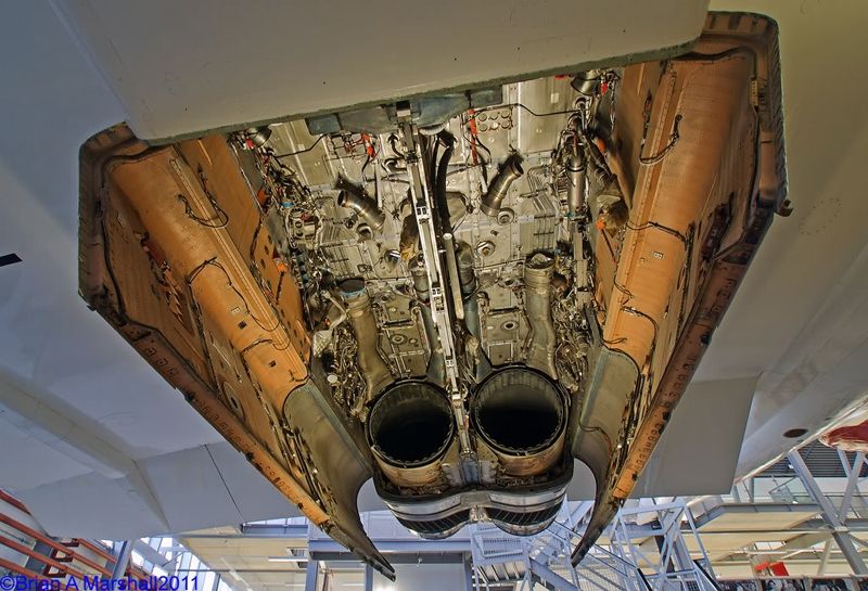
That really is a superb photo and shows just what a large but cramped affair the Concorde engine bay was. Although a pre-producion example, the picture generally shows what the production aircraft looked like inside the chasm. In the picture you can see the titanium roof of the engine bay that did such a good job in protecting the wing above (as was the case with the OAF engine failure in 1980 mentioned previously in this thread). What is missing from the 101s engine bay shown here are the air conditioning primary and secondary heat exchangers that were fitted above the engines. (The large trunking you can see coming forward from the jet pipes are the exhausts for the ram air from the exchangers). On a blunty, the heat exhangers are mounted in the belly of the aircraft, in what is generally known as a pack. But there was no room in Concorde for such lumpy bits, and so the only alternative was to mount them above the engine. The remainder of the equipment, the Cold Air Unit (or Air Cycle Machine as the blunties call them) as well as the, unique to Concorde, Fuel heat exchanger were mounted in the wings. With everything so sprawled about it could not really be called a 'pack' and so in Concorde we refered to an air conditioning GROUP.

The wiring you can see on the lower parts of the engine doors is generally Graviner fire wire, used for engine fire and nacelle overheat detection. At the forward part of the 2 doors (shown most clearly on the #4 engine) are two orange 'boxes. These are the engine bay ventilation 'ground running flap' electrical actuators (the flaps themselves being shown shut). Normally these spring loaded flaps would be open on the ground, being progreesively closed with increasing speed as engine bay pressure increased. The actuator would only run when the engine fire handle was pulled, to help seal off the bay. All the other orange stuff you can see is FTD, or flight teast wiring and equiment. (We used to not very kindly refer to it as 'orange s--t'
 ).
).
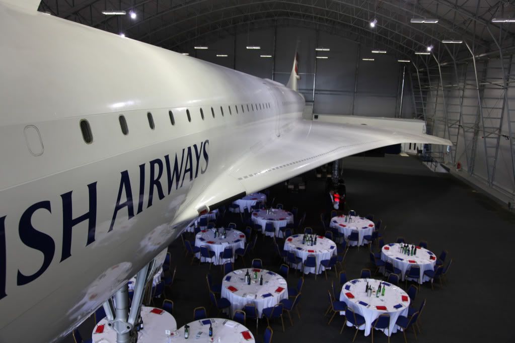
With regard to aircraft 204, G-BOAC I think you will find that all the engines are still installed. I took this photo (oops sorry, my wife did
 ) when we had a function in Manchester about 18 months ago. You can see what a wonderful job the folk up there are doing taking care of her, and as for dining under the wing.. it was truly a memorable experience indeed.
Best regards
Dude
Subjects
Engine Failure
G-BOAC
Links are to this post in the relevant subject page so that this post can be seen in context.
Reply to this quoting this original post. You need to be logged in. Not available on closed threads.
January 30, 2011, 13:45:00 GMT
permalink Post: 6212555
Tuesday 8th March 2011
18:00 - 19:30
Royal Aeronautical Society
No charge to attend. Non-members welcome.
Booking is not essential (you can just turn up) but the RAeS would appreciate an rsvp if possible.
Email (without the spaces): conferences @ aerosociety .com
More info about the lecture and the speakers here: LECTURE: Training Aircrew for Concorde
The RAeS is next door to the InterContinental Hotel.

Nearest tube stations -
Hyde Park Corner 3 mins.
Green Park 5-6 mins.
Perhaps a good opportunity for the Concorde enthusiasts here to meet?
The RAF Club is only a minute away from the RAeS - a very pleasant and interesting venue for a post-lecture drink and chat, and much cheaper than the Mayfair hostelries. There's a good chance of meeting a member of the Club who will be able to sign in guests. (If I'm able to attend the lecture I'd be happy to do so.)
Tudor Owen
Last edited by Flying Lawyer; 30th January 2011 at 14:07 .
Subjects: None
No recorded likes for this post (could be before pprune supported 'likes').Reply to this quoting this original post. You need to be logged in. Not available on closed threads.
January 30, 2011, 19:07:00 GMT
permalink Post: 6213080
Dude - I DID say the pressure was peculiarly sensitive to angle, but I didn't remember those additional corrections. Amazing what memories this thread throws up

Subjects
Area Rule
Links are to this post in the relevant subject page so that this post can be seen in context.
Reply to this quoting this original post. You need to be logged in. Not available on closed threads.
January 30, 2011, 20:24:00 GMT
permalink Post: 6213206
--------------------------------------------------------
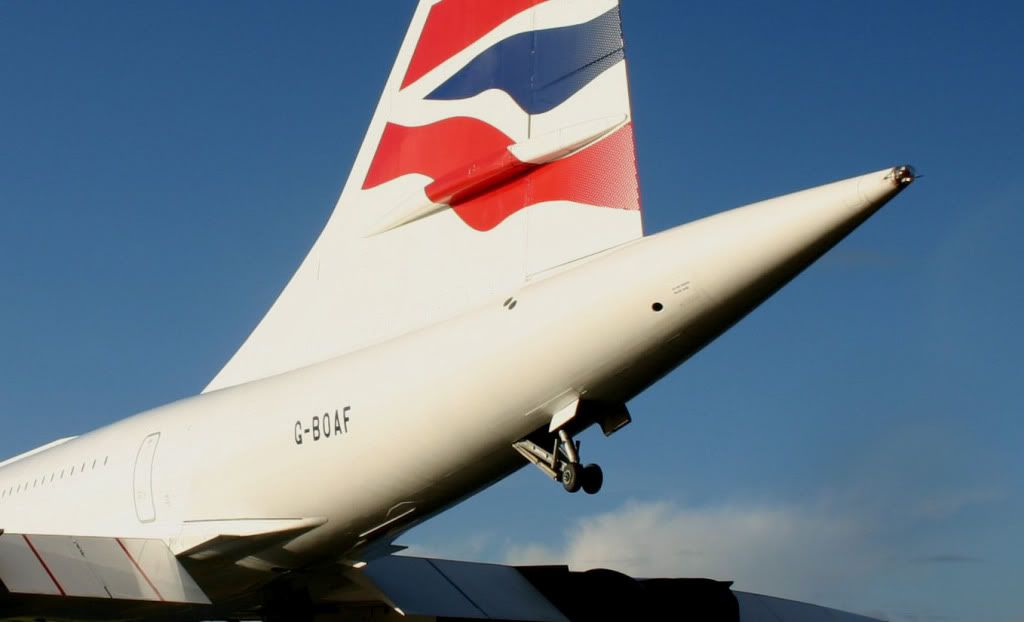
Nope. I meant the waisting of the fuselage where the fin starts. Stand on the steps by the front door where Dude's wife took that picture, and you'll see that the cabin roof is 'waisted in' noticably where the fin is mounted (not the sides of the fuselage which remain parallel - the roof, which is bowed inwards and downwards to reduce the fuselage cross section co-incident with the fin's extension above the fuselage). I see it several times a week on OAC.
You can see it on this picture too, though it's not as obvious as when you look back from the door.

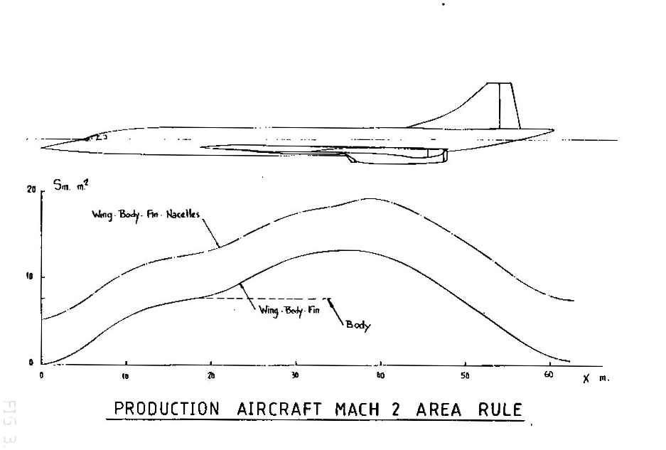
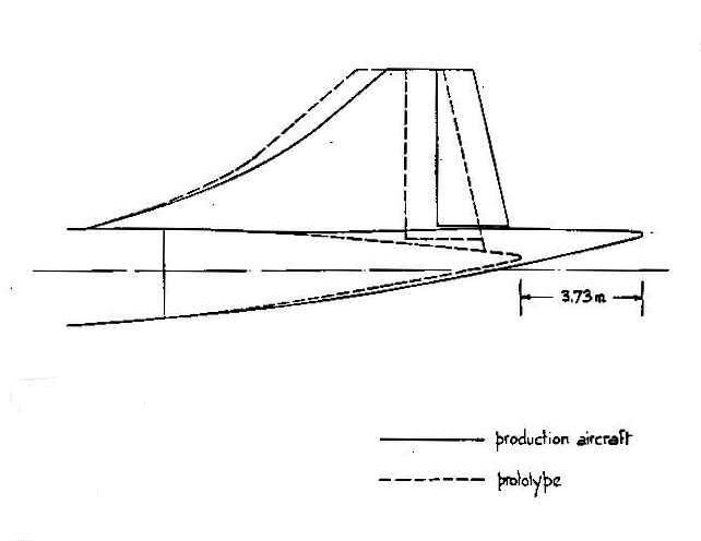
Mr Vortex - Yes, the gradual taper of the nose and of the tail help with area rule. As does the wing leading edge being brought as far forward as possible where it joins the fuselage, so the cross-sectional area increases as gradually as possible, nose to tail, at the wing root.
Last edited by Shaggy Sheep Driver; 31st January 2011 at 00:06 .
Subjects
Area Rule
Vortex
Links are to this post in the relevant subject page so that this post can be seen in context.
Reply to this quoting this original post. You need to be logged in. Not available on closed threads.
January 31, 2011, 11:08:00 GMT
permalink Post: 6214258
The OAF 'Mach 1 glitch' was pretty much from day 1, yonks before the nose job. All we were ever able to establish was that it was definately the ALTITUDE comparator tripping the red ADS master warning I established that one during a test flight. (At FL290 you needed around 350' comparison error between ADCs for at least 3 seconds in order to trip the warning). Trouble was the error was gone so quickly you never got very far. (And the AIDS/FDR system on OAF and OAG only took readings from #1ADC, and not both as was the case with the original 5 aircraft, so the FDR was not much help either).
ChristiaanJ
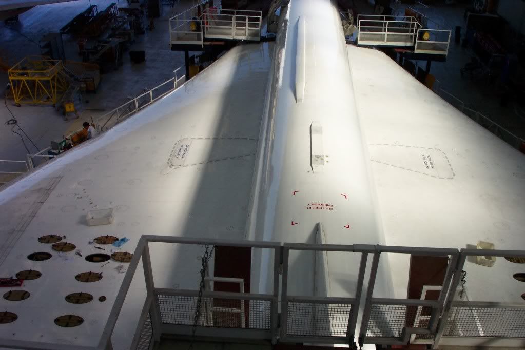
This view from the top of the fin shows it all quite clearly.
Best regards
Dude
Last edited by M2dude; 31st January 2011 at 12:13 . Reason: Correcting age related mistakes
Subjects
ADC (Air Data Computer)
Links are to this post in the relevant subject page so that this post can be seen in context.
Reply to this quoting this original post. You need to be logged in. Not available on closed threads.
January 31, 2011, 13:50:00 GMT
permalink Post: 6214565
This one really shows it up Alpha Fox after last landing at Filton.
 ">
">
Cheers
CL
Last edited by CliveL; 1st February 2011 at 08:58 . Reason: addition of picture
Subjects
Filton
Links are to this post in the relevant subject page so that this post can be seen in context.
Reply to this quoting this original post. You need to be logged in. Not available on closed threads.
February 07, 2011, 16:21:00 GMT
permalink Post: 6229745
Nice one... never heard that one before.
I think it's another urban legend...
Here's the "artist impression" that may have started the legend...
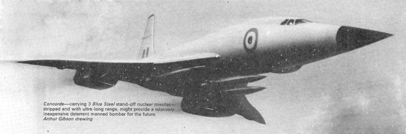
Also, there was a James Bond film, where they'd hung a couple of cruise missiles under a Concorde, which did look a bit like ASMPs.
CJ
Subjects: None
No recorded likes for this post (could be before pprune supported 'likes').Reply to this quoting this original post. You need to be logged in. Not available on closed threads.
February 08, 2011, 16:01:00 GMT
permalink Post: 6231804
AZR - The MOD did ask us to look at a military application, but it didn't take long to show that it just wasn't on, and it soon got dropped
AJ - The print room below #4 DO - you have just explained a lot! Pain in the neck if you needed a drawing urgently
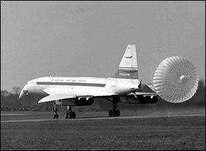
DM - The prototypes had brake parachutes and escape hatches, but I don't remember ever having to even think about spinning!
 ">
">
CSL
Last edited by CliveL; 8th February 2011 at 16:03 . Reason: add photo
Subjects: None
No recorded likes for this post (could be before pprune supported 'likes').Reply to this quoting this original post. You need to be logged in. Not available on closed threads.
April 05, 2011, 08:23:00 GMT
permalink Post: 6351256
1) The first shock was generated from the top lip of the intake
2) A second shock is generated from the fwd ramp hinge
3) A third isentropic fan shock is generated from the progressively
curved section of the fwd ramp
4) A 4th shock was generated fron the bottom lip
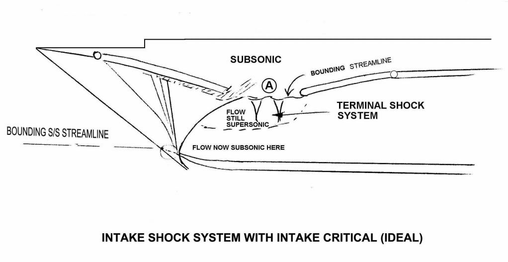
5) A terminal shock system is generated by the coalescence of
still supersonic and now subsonic air at the upper section of the ramp
area.
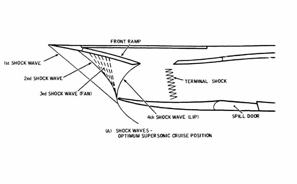
Hopefully these two diagrams will help. The first hand illustration above gives the 'theoretical' shock pattern and the second below gives an illustration of practical flows within the inlet. Both assume critical operation at Mach 2.
I hope all this blurb helps
Best regards
Dude
Last edited by M2dude; 5th April 2011 at 08:35 .
Subjects
Intakes
Shockwave
Links are to this post in the relevant subject page so that this post can be seen in context.
Reply to this quoting this original post. You need to be logged in. Not available on closed threads.
April 22, 2011, 17:31:00 GMT
permalink Post: 6406530
* Most deltas develop some vortex lift, and there were several deltas flying long before Concorde, so the phenomenon was not unknown.
Shaping the wing, and in particular the leading edge, optimised the effect on Concorde.
* The ogee (slender delta) wing was original proposed by NASA (possibly still NACA at the time) as best suited for a supersonic transport. The information was in the public domain by the time the "BAC223" and "Super Caravelle" were first revealed (they later "merged" into the Concorde design).
The Tu-144 design used the same information, which is a major reason for its resemblance to Concorde, rather than espionage...
How much the full advantages of the 'vortex lift' were understood at the time, is still an open question, IIRC.
I'll have to look for the original NASA TN (Tech Note)... it may be on the web somewhere.
* I would think the Handley Page HP115 slender-delta low-speed test aircraft must have contributed some details about vortex lift.

Sorry, I can't find my own photos of the beast.
It's now in the Fleet Air Arm Museum at Yeovilton (UK), together with Concorde 002 and the BAC-221.
It still has the "smoke tube" on the left wing leading edge, that was used to visualise the vortex over the wing (not yet fitted when the photo above was taken).
CJ
Subjects
BAC221
HP-115
HP115
Tu-144
Vortex
Links are to this post in the relevant subject page so that this post can be seen in context.
Reply to this quoting this original post. You need to be logged in. Not available on closed threads.
April 27, 2011, 00:42:00 GMT
permalink Post: 6414250
Is this what you wanted ?

Subjects: None
No recorded likes for this post (could be before pprune supported 'likes').Reply to this quoting this original post. You need to be logged in. Not available on closed threads.
June 20, 2011, 19:23:00 GMT
permalink Post: 6525487
 ">
">
If anyone wants more, the source is an AGARD CP 260 by Cazenove and Ivroas ( but I have not been able to access the only URL that comes up on Google!)
CliveL
Subjects: None
No recorded likes for this post (could be before pprune supported 'likes').Reply to this quoting this original post. You need to be logged in. Not available on closed threads.
June 20, 2011, 22:14:00 GMT
permalink Post: 6525802
Subjects: None
No recorded likes for this post (could be before pprune supported 'likes').Reply to this quoting this original post. You need to be logged in. Not available on closed threads.
December 06, 2011, 12:53:00 GMT
permalink Post: 6845526
I had a look on the eBay link and I question the engine model - the Forward Bearing supports are 5 struts but not the same configuration as the Series 200. I thought the 593 was derived from the 300 Series.
see below a picture of a 593 from Wiki:

File
 lympus593.JPG - Wikipedia, the free encyclopedia
regards
Howie
Last edited by howiehowie93; 6th December 2011 at 20:56 . Reason: trying to get the front view of the eBay engine on here fo comparison - massive fail !
Subjects
Olympus 593
Links are to this post in the relevant subject page so that this post can be seen in context.
Reply to this quoting this original post. You need to be logged in. Not available on closed threads.
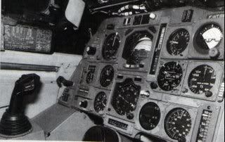
December 17, 2011, 12:59:00 GMT
permalink Post: 6905869
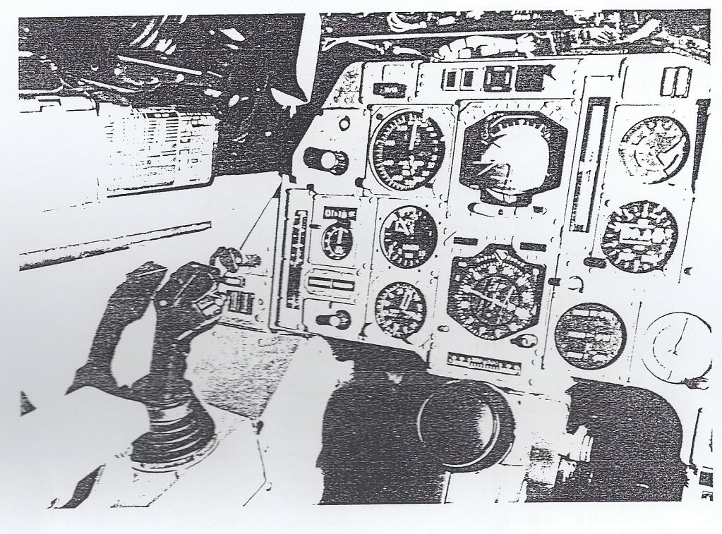
... I wondered how you could chose to fly in Track instead of Heading i.e. did you say have to push the button quickly twice to get the track mode?...
We should establish which button you mean, because there are two buttons , both associated with TRK/HDG, either of which might be the one you are referring to.
On the auto flight control panel there is a white push-button switch engraved with the letters TRK and HDG .

Photo courtesy of, and copyright to, Gordon Roxburgh , from his ConcordeSST.Com website.
When pressed, this will initiate the acquisition and subsequent hold of the preselected track or heading selected on the three digit counter beneath it (and repeated on the track/heading pointer on the HSI). This switch will illuminate White when this mode is engaged.

Photo courtesy of, and copyright to, Gordon Roxburgh , from his ConcordeSST.Com website.
So what determines whether this mode, if selected, would follow TRK or HDG? Beneath the three digit counter is a combined push-pull and rotary control, beside which is marked HDG PULL and TRK PUSH .
The rotary function of this control altered the reading in the counter and the Push/Pull function determined whether the entered number was a TRK demand or a HDG demand. With TRK/HDG illuminated on the push-button control, and with the rotary control pulled out (and thus in HDG mode), this little rotary control was effectively the steering wheel for the aircraft.
Why HDG and not TRK? Mainly because nearly all ATC vectors are HDG vectors. In practice TRK was rarely used, with the aircraft either in HDG or INS.
Best Regards
Bellerophon
Subjects
INS (Inertial Navigation System)
Links are to this post in the relevant subject page so that this post can be seen in context.
Reply to this quoting this original post. You need to be logged in. Not available on closed threads.
April 06, 2012, 19:42:00 GMT
permalink Post: 7121591
SORRY - senior moment - this should have been posted on another thread!

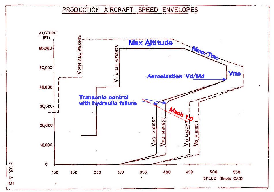
To be honest I can't remember exactly why 530 kts was chosen for the supersonic Vmo, but it was probably the best climb speed.
Mmo/Tmo was limited by a combination of intake and structural temperature.
The 'cut-off' in the sloping/530 kts boundary was, if I remember correctly, to avoid a minor aeroelastic problem at the Vd/Md condition one arrived at from that corner.
The variation of Vmo with weight was a device which, when associated with the CG corridor, allowed the aircraft to meet the manoeuvre requirements when flying on half hydraulics.
400 kts CAS gave 0.93M at around 28000 ft if I recall correctly, which was just below drag rise and gave optimum subsonic cruise performance
Last edited by Jetdriver; 21st April 2012 at 00:33 .
Subjects
C of G
Intakes
Vmo
Links are to this post in the relevant subject page so that this post can be seen in context.
Reply to this quoting this original post. You need to be logged in. Not available on closed threads.
April 27, 2012, 22:06:00 GMT
permalink Post: 7159745
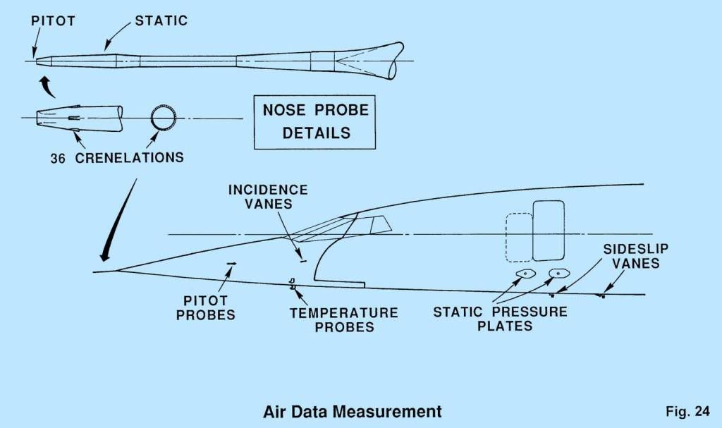
SSD:- this answers your question on where the TAT probes were located. Strictly, you don't need temperature to calculate Mach as it is independent of temperature when expressed in EAS (or CAS) terms.
Shane:
The "crown modifications" were external straps to be applied to the upper part of the fuselage to extend its life in those areas which had been designed to safe life concepts - basically the Aerospatiale bits since BAe designed their bits according to damage tolerance rules. It wasn't a small job, but I'm afraid I can't tell you how many aircraft were modified.
Subjects
Aerospatiale
Crown Modification
TAT (Total Air Temperature)
Links are to this post in the relevant subject page so that this post can be seen in context.
Reply to this quoting this original post. You need to be logged in. Not available on closed threads.