August 13, 2010, 18:53:00 GMT
permalink Post: 5867846
Not quite sure about your reference to the RAT on an F16 being Hydrazine powered; a Ram Air Turbine is just that, using the freely rotatting propellor to power hydraulics, electrics or both. Or do you mean the the F16 has an emergency power unit? Either way, it's fascinating stuff.
Yes, I do remember that the Germans used Hydrazine as a fuel during WW2: The father of one of our Concorde pilots was on an air raid to destroy one o the production plants there, this aviation business is such a small world.

Subjects
Cabin Crew
Flight Envelope
Hydraulic
Hydrazine
IAS (Indicated Air Speed)
Intakes
JFK
LHR
N1 (revolutions)
Olympus 593
RAT (Ram Air Turbine)
Relight
Links are to this post in the relevant subject page so that this post can be seen in context.
Reply to this quoting this original post. You need to be logged in. Not available on closed threads.
August 16, 2010, 12:09:00 GMT
permalink Post: 5872914
Both A/C 214 (OAG) and 216 (OAF) were Variant 192 A/C (British Unsold A/C). 216 was later converted to a 102 (British Airways) Variant, where 214 more or less stayed as a Variant 192. I'm not disputing what you say about possible APU mountings (I guess it would HAVE to be at the front section of the lower cargo hold somewhere) but I for one have certainly never seen any evidence of them. I'm still trying to imagine where the air inlet and exhausts would have to be arranged, not to mention pneumatic services ducting/hydraulics. Wouldn't it be interesting to find out?
Subjects
APU (Auxiliary Power Unit)
G-BOAF
G-BOAG
Intakes
Links are to this post in the relevant subject page so that this post can be seen in context.
Reply to this quoting this original post. You need to be logged in. Not available on closed threads.
August 17, 2010, 10:50:00 GMT
permalink Post: 5874791
 ).
).
As far as the MEPU goes, all it really did was drive 2 hydraulic pumps; the Green System then powering the 40 KVA emergency generator; unless you are going to use the APU for engine starting and ground air conditioning, then I honestly don't think that there would be much point. It's interesting also to note that the MPU, being a rocket motor, needed no air intake, and as it was not driving any huge loads, the exhaust duct dould be quite narrow.
Subjects
APU (Auxiliary Power Unit)
G-BBDG
GREEN Hydraulic System
Hydraulic
Intakes
MEPU (Monogol Emergency Power Unit)
Links are to this post in the relevant subject page so that this post can be seen in context.
Reply to this quoting this original post. You need to be logged in. Not available on closed threads.
August 17, 2010, 14:33:00 GMT
permalink Post: 5875273
Nice set of photos of "The Thing" here :
MEPU at MAE at le Bourget .
This one is at the Air and Space Museum at Le Bourget, near Paris. My guess is that is was a spare, since the manufacturing date is 1973. 'SA flew in January '73 and 'SB in December '73.
IIRC, Delta Golf arrived at Brooklands with the MEPU still in place; I might have a photo.
As to the installation, we're obviously thinking along the same lines....
However, there were already several conduits through tank 11, such as hydraulics for the tail wheel, various electrics, and the 'backbone' fuel manifolds, that ended at the fuel jettison port in the tailcone.
A couple of fairly substantial air ducts would only have displaced a few hundred kgs of fuel at the most, out of the more than 10,000 kgs in tank 11.
And yes, of course, the whole point of the APU would be to have independent ground start and ground airco available, so clearly an APU would have been bigger and heavier than the MEPU (which was only just over 80 lbs), plus the problem of the air intake and bigger exhaust.
I'd have to get the drawings out to see how easy or difficult it would have been to fit one in the available space.
Since the tailcone was BAC, and both 214 and 216 were built at Filton, I wonder if anybody there still remembers?
Subjects
APU (Auxiliary Power Unit)
Brooklands
Filton
G-BBDG
G-BOAF
G-BOAG
Intakes
Le Bourget
MEPU (Monogol Emergency Power Unit)
Tail Cone
Links are to this post in the relevant subject page so that this post can be seen in context.
Reply to this quoting this original post. You need to be logged in. Not available on closed threads.
August 19, 2010, 11:16:00 GMT
permalink Post: 5879669
Stupid, you? no way!! (Besides, I'm Mr Stupid of the aviation world, that's my title
 ). The thing is, out here in the world of flying machines, there are almost an infinite number of questions (and hopefully answers too). This applies to just about all aircraft from the Wright Flyer up!!.
Keep asking away, there are so many of us Concorde 'nuts' out here who are more than happy to help out/bore the socks off you.
Fuel burns: The problem was that when flying slow/taxying, Concorde was an extreme gas guzzler, even when idling each engine burnt around 1.1 tonnes/hour (so every 15 minutes after push back meant over a tonne gone). A typical taxi fuel would be around 1.4/1.5 tonnes, depending on the runway in use on the day. I'd have to leave it to some of my pilot/F/E friends to remember some of the specific fuel burns after take off etc, but I can at least give you some interesting consumption figures:
At the beginning of the take off roll, each engine would be burning around 21 tonnes/hour. (Made up of around 12 T/Hr dry fuel (Fe) and 9T/Hr afterburner (reheat to us Brits) fuel (Fr). As Fr was scheduled against Fe, as a function of inlet total temp (T1) by the time V2 was reached (around 220 KTS) the rising T1 has pushed the total fuel flow (Ft) up to a staggering 25 tonnes/hour/engine. As i've pointed out before in previous topics, although the afterburner only gave us a 17% improvement in take off thrust, it was responsible for around an 80% hike in fuel burn. (Hence that is whay it was only used sparingly). However when reheat was used for transonic acceleration, it used a dramatically reduced schedule (roughly a 60% rise in fuel flow) , so it was not quite as scary. The afterburner would be lit at the commencement of the acceleration (0.96 Mach) and cancelled completely at 1.7 Mach. After this time the aircraft would accelerate on dry power only up to mach 2 and beyond. (The cooler the temperature the quicker the time to Mach 2). On an ISA+ day, it sometimes felt that the aircraft was flying through cold porridge, and could take quite a while to get to Mach 2 after reaheat cancellation, where as on a nice ISA - day, she would go like a bat out of hell, and the AFCS would have to jump in to prevent overspeeds.
Before I hit some more numbers, let me say that with Concorde, TOC = TOD!! After reheat cancellation at Mach 1.7, the aircraft would be at FL 430. The aircraft would climb at an IAS of 530 KTS until Mach 2 was reached at fractionally over FL500. From then on the aircraft would cruise/climb as fuel was burnt, up to a maximum of FL600. On warmish days (eg. the North Atlantic) TOD would typically be around FL570-580. On a cool day (the lowes temperatures would of course be reached in the more tropical regions; the LGR-BGI sector encountered this), FL 600 would be reached easily and she would love to climb some more. BUT, the aircaft was only certificated to 60,000' with passengers onboard, for decompression emergency descent time reasons, and so we were stuck with it. The pity is of course, the fuel burn would have been improved, but we never were able to take advantage of this. On test flights however, the aircraft would routinely zoom climb to FL 630. On her maiden flight, aircaft 208 (G-BOAB) reached an altitude of 65000'; the highest recorded Concorde altitude was on one of the French development aircraft, which achieved 68,000'. On a technical point, the analog ADC's were 'only' calibrated to 65,000'.
Anyway, back to some figues; at Mach 2, 50,000', the typical fuel burn per engine would be around 5 tonnes/hour, falling to around 4.2 tonnes/hour at 60,000'.
THE NOSE You are quite correct in your assumption, there were two positions of droop: 5 deg's for taxi/take-off and low speed flight and 12.5 deg's for landing. The glazed visor retracted into the nose and could ONLY be raised once the nose was fully up, and had to be stowed before the nose could move down. There were 2 emergency nose lowering sysyems; one using stby (Yellow) hydraulics and a free-fall system. Free-fall would drop the nose all the way to 12.5 deg's, the visor free falling into the nose also.
Last edited by M2dude; 19th August 2010 at 12:40 . Reason: mistooks
Subjects
ADC (Air Data Computer)
AFCS (Automtic Flight Control System)
Afterburner/Re-heat
Depressurisation
FL600
Fuel Burn
G-BOAB
IAS (Indicated Air Speed)
Intakes
Transonic Acceleration
V2
Visor
Links are to this post in the relevant subject page so that this post can be seen in context.
Reply to this quoting this original post. You need to be logged in. Not available on closed threads.
August 20, 2010, 12:06:00 GMT
permalink Post: 5881873

The engine itself, being supplied with air at an ideal pressure, could run at an almost conststant TET, thanks to the variable primary nozzle. This also allowed N1 and N2 (corrected for total temperature) to be controlled more or less independently and run as close as possible to their separate surge lines throughout the entire flight envelope.
The variable secondary nozzle (wide open above Mach 1.1) allowed the jet efflux to gently expand against a cushion of air that was passed over the rear ramp of the intake, through the engine bay and into the annulus of the nozzle itself. This prevented thrust being wasted by the jet efflux widely splaying as it met ambient air that was at a pressure of as little as 1.04 PSIA.
It was this integrated powerplant that made true supersonic cruise possible
 ). There was a design flaw here in that the structure had not been designed fail-safe (allegedly by designed a Korean designer at A\xe9rospatiale who, it was said, went a bit loopy). When the FAA evaluated the design (in order for the aircraft to be registered in the USA, for Braniff operations out of IAD) they wanted 'crown planking' to be fitted externally, which would have added over a tonne to the weight of the aircraft, as well as producing some not inconsiderable drag. Fortunately a compromise was reached and additional NDT inspections were carried out, as well as more limited structural modifications. There was a long term, cost effective solution being studied, which would have cured the problem altogether. (The changes would have been mandated, over new requirements for ageing aircraft)
Nick Thomas
Nick, the whole expansion issue was one of the biggest issues that had to be addressed. Wiring looms would 'snake' in some underfllor areas to take up expansion, but the biggest difficulty of all were the mulitudes of hydraulic lines. These required sliding expansion joints, with of course seals to prevent leakage. When a seal deteriorated YPU GOT A LEAK!! (Fluid at 4000 PSI tends torun for freedom very quickly
 ). As far as fittings go, ChristiaanJ is quite right, you tried to anchor at one end only. I seem to remember that the passenger seat rails travelled over a roller afair. Fuel lines wer less of a problem, because their relative lengths were less.
I also agree wholeheartedly with ChristiaansJ's explanation about the 'friction' thing, I never really liked those stories. As a matter of interest, 127 deg's, for Mach 2, that would be at ISA +5 (-51.5 deg's C). Any warmer than that and we could not achieve Mach 2, due to the Tmo limit of 127. I remember one year, for several weeks we had unusually high north Atlantic temperatures; these impacted both the flight time AND the fuel burn. The further away you were from Mach 2, the higher the fuel consumption. (The faster you flew, the less fuel you burnt. How's that for a paradox?).
At ISA (-56.5 deg's C) temperatures, the total temperature was at around 118 deg's C.
ChristiaanJ
I remember the 17.5 degree position on the nose; it always looked as if the aircraft was trying to eat ants to me
 . I can not recall personally anyone removing the 12.5 deg' stops for access, although this could of course have been done on your side of the 'puddle' I guess.
As far as the APU ducting issue goes (hee, hee, not often we disagree Christiaan
 ) we are just going to have to agree to disagee about this, although I accept that two 4" diameter pipes (PLUS THERMAL INSULATION) might have done it, BUT I still stand by the other points.
Stlton
Its all academic now but, just out of curiosity could this have worked on the Concorde
Subjects
APU (Auxiliary Power Unit)
Afterburner/Re-heat
Braniff
Engine surge
Expansion
Flight Envelope
Fuel Burn
Hydraulic
Intakes
N1 (revolutions)
Nozzles
TMO (Temprature Max Operating)
Temperature Shear
Links are to this post in the relevant subject page so that this post can be seen in context.
Reply to this quoting this original post. You need to be logged in. Not available on closed threads.
August 20, 2010, 23:21:00 GMT
permalink Post: 5883057
As far as the APU ducting issue goes (hee, hee, not often we disagree Christiaan
) we are just going to have to agree to disagee about this, although I accept that two 4" diameter pipes (PLUS THERMAL INSULATION) might have done it, BUT I still stand by the other points.
So I happily agree to disagree on the rest... between the two of us, each looking at our own clues, and with the help of anybody else who has more info, we might still find the answer!
One thought I had... with an APU in the forward baggage hold, you'd also have to take the air intake and exhaust through the pressure hull, and provide sound and thermal insulation for the entire APU itself.
From a design point of view, I'd have gone for the same location of the earlier pseudo-APU (the MEPU), and then solved the remaining problems from that starting point.
Subjects
APU (Auxiliary Power Unit)
G-BOAF
G-BOAG
Intakes
MEPU (Monogol Emergency Power Unit)
Links are to this post in the relevant subject page so that this post can be seen in context.
Reply to this quoting this original post. You need to be logged in. Not available on closed threads.
August 22, 2010, 01:47:00 GMT
permalink Post: 5884837
So yes, on the whole, TOC did equal TOD.
The 'subsonic climb' wasn't quite as you thought; you'd normally subsonic climb to FL280, staying there (at Mach 0.95) until the acceleration point. Mach 0.95 was 'subsonic cruise'. But you were on the right track.
Oh, and NOPE, they never boomed us either
Nick Thomas
The only problem you ever had with the dual nacelle arrangement was if you had an engine surge above Mach 1.6 (These were relatively rare, but could happen with an engine or intake control system malfuntion). If one engine surged, the other would surge in sympathy, because of the shock system being expelled from one intake severely distorting the airflow into it's neighbour. These surges were loud, quite scary (to the crew that is, most passengers never noticed much), but in themselves did no damage at all. Delicate movement of the throttles (employed during the subsequent surge drill) would invariably restore peace and harmony again to all. (The intake on Concorde was self-starting, so no manual movement of the intake variable surfaces should be needed in this event). After this was over, normal flying was resumed again As I said before, these events were relatively rare, but when they did occur, they would be dealt with smartly and professionally; the engine and intake structure being undamaged. (Post surge inspetion checks were always carried out on the ground after an event, on both engine and intake, but nothing much was EVER found).
Subjects
AFCS (Automtic Flight Control System)
Engine surge
Fuel Burn
G-BOAF
Intakes
JFK
LHR
LHR-JFK Route
LP Compressor
Rolls Royce
Shannon
Vmo
Links are to this post in the relevant subject page so that this post can be seen in context.
Reply to this quoting this original post. You need to be logged in. Not available on closed threads.
August 22, 2010, 03:45:00 GMT
permalink Post: 5884915
... My other query concerns the FE. I understand that he set take off power etc...
Actually the F/E didn’t set T/O power, but did set most of the other power settings.
Broadly speaking, taxy-out to gear up, and gear down to engine shut down, the handling pilot operated the throttles. At other times, it was (almost) always the F/E.
Bear in mind that several of the routine engine power changes were effected through controls other than the throttles. For instance, selection of the re-heats, engine control schedules, engine ratings and intake lanes were all switch selections.
... I also understand that he also checked the pilots inputs into the INS system...
Correct, using INS3.
...So was he/she also a qualified pilot?..
No, they were professional flight engineers, who held a Flight Engineers Licence; they were not pilots biding their time before moving to the right hand seat.
I believe one or two may have held a PPL, but that was purely incidental, not a requirement.
All of the Concorde FEs had spent years on the VC10, B707, DC10, L10-11 or B747 fleets before coming to Concorde.
Biggles78
...Am I right or even slightly so in thinking that cruise climb and cruise descent was the flight...
Cruise climb, yes. Cruise descent, no.
...and there was minimal actual level cruise in the "pond" crossing?..
Correct, any level flight in the “cruise”, was just coincidence, probably caused by the outside air temperature increasing very gradually. Typically, she drifted up at around 30 to 50 fpm, but, if encountering warmer air, she would start to drift back down, in order to maintain M2.0.
... As you have said, fuel flow was reduced the higher you got. I think it was 5T per powerplant at FL500 down to 4.1T at FL600...
Rather optimistic figures for FL500 I’d have said! 6,000kg/hr/engine would have been nearer the mark!
...I am curious to see how much less fuel would have been used at the higher FLs considering it was reduced by 900Kg/hr for just 10K feet...
The reason the fuel flows dropped so much at the higher altitudes was that the aircraft had to be a lot lighter before she would get up there. It was her lighter weight that was the primary reason for the reduced fuel flows, not the higher altitude.
Forgive me if I’ve misunderstood you, but in her cruise climb, Concorde was flown at her optimum speed (M2.00) with (constant) optimum power set (max cruise power) and so (assuming a constant OAT above the tropopause) the only thing which affected her cruising altitude was her weight.
So, in theory at least, in cruise climb, she was always at her optimum altitude.
Any variation from that optimum altitude, such as a premature climb to higher altitudes, would have cost fuel, not saved it.
... How much of the descent was carried out while supersonic...
At the decel point, the cruise climb ceased and she was flown level at constant altitude. The F/E partially throttled back the engines and she stayed in level flight until her speed reduced to 350kts IAS, typically M1.5.
This took about 50nm, and most of the passengers would have sworn that they were already descending.
She then descended at 350kts IAS, meaning the Mach number would reduce constantly. On a straight in approach to JFK, with no subsonic cruise section, she would become subsonic descending through (around) FL350.
For a straight in approach, in zero wind, on a standard day, from FL600 to touchdown, typical figures would be something like a track distance of around 200nm, flying time of 22 minutes and 3,500kg of fuel.
Into LHR, she had to be subsonic much further away from her destination, and then had a subsonic cruise section on airways, so a slightly different procedure was used, and approaching FL410 she was slowed still further, becoming subsonic around FL400.
Anonymous
In response to your PM, earlier posters were correct in what they posted, however the manual reversion they refer to is a reversion from electrical to mechanical signalling to the flying controls.
There was no way to operate the flying controls manually in the absence of hydraulic power.
Subjects
Afterburner/Re-heat
Boeing 747
FL600
Fuel Burn
Hydraulic
IAS (Indicated Air Speed)
INS (Inertial Navigation System)
Intakes
JFK
LHR
Links are to this post in the relevant subject page so that this post can be seen in context.
Reply to this quoting this original post. You need to be logged in. Not available on closed threads.
August 23, 2010, 13:20:00 GMT
permalink Post: 5887403
Last edited by M2dude; 24th August 2010 at 08:31 . Reason: A few corrections
Subjects
Intakes
LP Compressor
N1 (revolutions)
Vortex
Links are to this post in the relevant subject page so that this post can be seen in context.
Reply to this quoting this original post. You need to be logged in. Not available on closed threads.
August 24, 2010, 09:48:00 GMT
permalink Post: 5889012
Does anyone have a tech drawing of the "sliding seals" used in the hydraulics. I have trouble visualising something that could withstand the 4,000psi pressure. Why was such a high pressure used? After all the control surfaces couldn't have required that much input to effect an authority movement. I understand it was also a special fluid that was used. Was this because of the pressure it was under or the temperature extremes?
).
As far as the hydraulic expansion joints go, I will scour around and see if I can find a diagram for you. Try and picture two titanium (or stainless) tubes, on inside the other, with a sealed chamber being formed at the join. Inside this chamber were multiple lands fitted with special viton GLT seals. They did work incredibly well, although occasionally one of the seals gave out, and things got wet, VERY WET.
As far as the 4000 PSI hydraulic system, as EXWOK quite rightly pointed out, the loading on the flying control surfaces were immense throughout the whole flight envelope. (Picture alone just the T/O from JFK RWY 31L, where the aircraft is tightly turning and the gear retracting, all at the same time). As well as the flying controls and landing gear, you also had the droop nose to consider, four variable engine intakes as well as a couple of hydraulically operated fuel pumps. Oh, and in emergencies, a hydraulically driven 40 KVA generator too. The reason that 4000 PSI was chosen was that if a large amount of hydraulic 'work' was to be done, the only way to keep the size of jacks and actuators to a reasonable size/weight was to increase the system pressure by 25% from the normal 3000 PSI. (On the A380 they've gone a step further and gone for 5000 PSI, saving them over a tonne on the weight of the aircraft).
Concorde used a special hydraulic fluid, Chevron M2V. This is a mineral based fluid, as opposed to the ester based Skydrol, used by the subsonics. The reason that we went for a different fluid was a simple one; Skydrol is rubbish at the high temperatures that Concorde operated at, no good at all in fact, so we needed something better and in M2V we found the PERFECT fluid. As an aside, unlike Skydrol, that attacks paintwork, certain rubber seals, skin, EYES etc., M2V is completely harmless, wash your hair in it. (I did, several times when we had leaks. Thinking about it, maybe THAT is why my hair is such a diminished asset

EXWOK
It's so great having another of my pilot friends diving in to this post, welcome welcome
I remember the Mech' Signalling part of the air tests, my lunch has just finished coming back up thank you.
 (for interest chaps and chapesses, with mechanical signalling, using just the conventional control runs under the floor, there was no auto-stabilisation).
The artificialfeel system worked incredibly well I thought, I always found it curious that the peak load law in the computer was at the transonic rather that the supersonic speed range. It was explained to me long ago that this was because the controls really are at their most sensitive here, but at high Mach numbers are partially 'stalled out', due to shockwave movements along the surfaces, and were therefore less effective. (For this reason I was told, the inner elevons were so critical for supersonic control, being the most effective of all elevons at high speed).
To all , I forgot to mention in my previous post regarding the engine failure in G-BOAF in 1980; I remember an FAA surveyor, who was taking a look at the carnage within the engine bay, saying that in his opinion, no other aircraft in the world could have survived the intensity of the titanium fire that ensued. Analysis showed that the fire was successfully extinguished, possibly at the first shot of the fire bottle. This was a testament to the way that the Concorde engine bay could be completely 'locked down' when the fire handle was pulled, as well as to the way that the whole engine installation was technically encased in armour plate. To put all this in context, acording to Rolls Royce a titanium fire, once it takes hold, can destroy the compressor of a jet engine in four seconds.
Dude
Subjects
Airbus
Elevons
Engine Failure
Expansion
Flight Envelope
Fuel Pumps
G-BOAF
Hydraulic
Intakes
JFK
Landing Gear
Rolls Royce
Shockwave
Tailwheel
Links are to this post in the relevant subject page so that this post can be seen in context.
Reply to this quoting this original post. You need to be logged in. Not available on closed threads.
August 24, 2010, 12:02:00 GMT
permalink Post: 5889280
Like so many in the Concorde family, I have millions, I'd like to share a couple here. I remember at Fairford in mid 1974, a CAA test pilot (I honestly forget the gentleman's name) was taking the British pre-production A/C 101 (G-AXDN) for a special test flight. The reason that this flight was so special was that for the first time, the CAA were going to do an acceptance flight trial of the brand new digital air intake system. This revolutionary system had been retro fitted to 101 barely a year earlier, and being a brand new (and totally unique, in electronics terms) system had been plagued with teething troubles. It was quite reasonable for any airworthiness authority to have serious misgivings about any system that was going to wave great big metal lumps around in front of the engine compressor face, and that if only a few degrees out from the commanded position out could cause the engine to 'backfire' etc.
So anyway, 101 took off and disappeared into the very blue sky and we waited, and waited, AND WAITED. (I'd only left the RAF and joined the project a few months previously, and did not want my new association with this amazing aircraft to end). I was biting my nails, drinking coffee, losing my hair... (without the help of M2V
). Anyway after about 2 1/2 hours the aircraft returned to Fairford, and everybody crowds around the crew for the debrief. A very stern faced CAA pilot looked at us all, broke into a grin and said "as far as I'm concerned gentlemen, you've got yourselves an airliner". At that point the room was a study of total happiness, blessed relief, and a need to go to the loo..... But from my point of view, I will remember those words forever.
101, which now resides at the Imperial War Museum Duxford was the fastest Concorde ever. She achieved Mach 2.23, which was an incredible irony, as Concorde can trace a large part of it's developement history back to the BAC 223, proposed SST.
As far as flying memories go, I just don't know where to start; My first ever Concorde flight was in November 1976, out of Fairford on a pre-delivery test flight on G-BOAD. (Now sadly bobbing up and down on the Hudson, next to the USS Intrepid). I was staggered how fast and high we flew (Mach 2.08, FL580). Most of my flying up to that date had been in C-130's in the RAF, at around 340 KTS and FL300; Concorde also being infinately quiter in flight than the good old Herc'. I remember a BA QA guy showing me how I could touch the skin of the aircraft at Mach 2 (You reached behind a door busstle flap, moved your hand through some insulation until you felt bare metal). OUCH!! it was hot, very hot.
But I think one of my most memorable flight memories was aboard G-BOAG, (now residing in the Boeing Museum of Flight in Seattle) returning from BKK, having stopped off to refuel in BAH. We were forced to fly subsonic over Saudi, and got caught in this amazing electrical storm, There was St Elmo's fire cracking and bubbling all over the visor panels, but just as incredible was the long blue electrical discharge coming off of the nose probe; it seemed to extend about 50' in front of the aircraft. The crime was, none of us on the F/D had a camera. Every time I bump into the captain on that day (are you reading this Ian?), we go back to remonissing about that incredible flight. Also, later on the same sector, after we had decelerated to subsonic cruise again, this time flying up the Adriatic, we had another fascinating sight: It was getting quite dark now, and here we were, travelling at Mach 0.95 at FL290, when above us was all this Mach 0.8 ish traffic at around FL330-350. All we could see were all these navigation and ant-coll' lights above us, seemingly travelling backwards. It was quite a sight. On the original BAH-BKK sector a week earlier, we flew through some of the coldest air I'd ever seen; The air was at ISA -25, and at Mach 2 our TAT was only about 85 deg's C. (You could feel the difference too; the cabin windows felt only warm-ish to the touch). The upside also of all this was that your fuel burn was much lower than usual. (The only downside of course is that your TAS is a little lower). Rolls Royce did some analysis on the flight, and were amazed at how well the propulsion systems coped with some of the temperature sheers that we encountered, sometimes 4 to 5 deg's/second. They said that the prototype AFCS had been defeated by rises of only 0.25 deg's/second ).
Not meaning to go off onto a (yet another) tangent; Negative temperature shears, very common at lower lattidudes, always plagued the development aircraft; you would suddenly accelerate, and in the case of a severe shear, would accelerate and accelerate!! (Your Mach number, quite naturaly, suddenly increased with the falling temperature of course, but because of the powerplant suddenly hitting an area of hyper-efficiencey, the A/C would physically accelerate rapidly, way beyond Mmo). Many modifications were tried to mitigate the effects of severe shears, in the end a clever change to the intake control unit software fixed it. (Thanks to this change the production series A/C would not be capable of level flight Mach numbers of any more than Mach 2.13, remembering that Mmo was set at 2.04).
There was one lovely story, involving the Shah of Iran, having one of MANY flights in a developmment aircraft. The aircraft encounterd quite a hefty series of temperature shears that plagued havoc with some Iranian F4's that were attempting to close on the Concorde, to act as an escort for the Shah. (or so the strory goes). I'm still trying to picture these F4's, on full afterburner trying to get close to a Concorde cruising away on dry power). It is said that the F4's were having such difficulties, due to their relatively crude powerplant, coping with the temperature changes, that the Concorde was ordered to slow down, 'so the escorting F4's could catch up'!! True or not, it is part of Concorde folklore.
Dude
Last edited by M2dude; 24th August 2010 at 15:31 . Reason: spelling (again) :-(
Subjects
AFCS (Automtic Flight Control System)
Afterburner/Re-heat
Boeing
British Airways
Captains
Fairford
Fuel Burn
G-AXDN
G-BOAD
G-BOAG
Intakes
Mmo
Rolls Royce
TAS (True Air Speed)
TAT (Total Air Temperature)
Temperature Shear
Visor
Links are to this post in the relevant subject page so that this post can be seen in context.
Reply to this quoting this original post. You need to be logged in. Not available on closed threads.
August 24, 2010, 15:25:00 GMT
permalink Post: 5889619
Thanks for bringing up the story of the temperature shears at low latitudes, saves me some explaining !
The phenomenon was not really "discovered" until the route proving started.
As you say, it meant abrupt changes in Mach and Tt.
Since the pitch autopilot in, say, 'Mach Hold', had only one way to cope with those changes : pitching up or pitching down, this resulted in abrupt climb and descent manoeuvres that were totally inacceptable.
It was not only fixed by modifiying the intake controls.... !
It also led to a fairly major mod in the AFCS, by bringing the auto-throttle into the loop.
Instead of letting the pitch A/P take the aircraft into a zoom climb to try and stay within the "speed limits", it woold be the autothrottle pulling the throttles back.
After a fair amount of flight tests, this became the final form of the 'Max Cruise' mode.
I know... I should have kept a diary.
All this happened 35 years ago, so I can't put exact dates, or even specific aircraft, into the story. At least I still have some Concorde doc, that at times allows me to refresh my memory.
But one thing stayed in my memory over the years ...
The initial A/P+A/T 'Max Cruise' mod meant a major modification of the autothrottle computers. One of the circuit boards in particular was totally "butchered" on-site (Fairford), with well over a hundred track cuts and new wire links, not to mention the number of component changes (to give an idea to the 'experts', these were double-sided PCBs of about 15x20cm).
We got the job done (4 boards : 2 boards per computer, 2 computers), got the computers tested and on the aircraft. Knowing full well how easy it was to introduce faults and problems during such a modification (a dud solder joint could be enough), we expected to see them back within days, or at least within a few flights.
Well..... those computers left the lab with each about a thousand hours "on the clock" (they have little elapsed-time counters that indicated hours under power, NOT flight hours).
The first time we saw them back (for a minor mod, not a fault), both clocks showed over 10,000 hours !
Ah, those were the days

CJ
Subjects
AFCS (Automtic Flight Control System)
Auto-pilot
Auto-throttle
Fairford
Intakes
Temperature Shear
Links are to this post in the relevant subject page so that this post can be seen in context.
Reply to this quoting this original post. You need to be logged in. Not available on closed threads.
August 24, 2010, 22:09:00 GMT
permalink Post: 5890279
Concorde "B"
Concorde '217' would have been the 'prototype' for the 'B' version. Sadly it never happened.
Yes, there was some industrial espionage, and a Russian or two was arrested with microfilms of blueprints and a few components, in the best James Bond style (this was in France, BTW...).
Some "duff gen" may have been passed as well... although the main reason the Concordski failed was that they didn't really get some of the vital stuff sorted, with the subtlety of the wing shape and the intake controls being only a few of the examples.
To my mind, the best story (urban legend or not) was that a Russian got caught scraping tyre deposits off the runway after a few accelerate/stop tests. The sample was duly sent to Russia, mixed with chewing gum and a few other ingredients, and a certain amount of time is reputed to have been wasted tryng to reproduce the 'formula".....
Legend also has it, that the Russians at one point quite seriously inquired if they could buy the license to the intake control system.
Since at the time it would still have had quite significant military use as well, the answer was a very firm "njet" !
CJ
Subjects
Intakes
Tu-144
Links are to this post in the relevant subject page so that this post can be seen in context.
Reply to this quoting this original post. You need to be logged in. Not available on closed threads.
August 24, 2010, 22:49:00 GMT
permalink Post: 5890348
aaah yes, Max Climb/Max Cruise modes. I'd not forgotten this my friend, I was going to say a few words about that in a future post, but maybe we can do that now. (And I'd love to hear more of your comments on this here too, ChristiaanJ). The intake and autopilot modifications were in a way complimentary it's true, but really dealt with separate problems, at least in my view:
The intake control unit software change (a change to the control law that limited engine N1 as a function of intake local Mach number, Mo, and inlet total temperature, T1) was able to put an absolute limit on aircraft achievable Mach number during Mmo overshoots, but it would not PREVENT Mmo overshoots occurring altogether, it was more of a safety brake. This particular overspeed problem manifested itself well before route proving, and in fact the intake system 'fix' resulted in the Thrust Auto Reduce System being deleted, electronic control boxes and all. The TAR system was fitted on all development aircraft equiped with the digital intake system, and it tried (in vain) to limit extreme Mach overshoots. The production aircraft retained the TAR wiring and locked out circuit breakers, as well as two vacant spaces on the electronic racks. The prime reason for all these efforts were that some of the rapid excessive Mach overshoots quite often drove the intake into surge; the modification to this N1 limiter control enabled engine mass flow to be controlled in such a way that these surges could be prevented during temperature shears. The aircraft Mach limit was an extremely useful fringe benefit.
The AFCS mode change from what was Max Op and Max Op Soft (always loved that name) to Max Climb/Max Cruise was at a stroke able to deal with the regular Mmo overspeeds that kept on occuring during, as you say, the route proving trials of 1975, when British aircraft G-BOAC and the French aircrfraft F-BTSD carried out pre entry into service evaluation flights, SD sadly was the aircraft that was tragically lost at Gonez in July 2000). The Max Climb/Max Cruise AFCS mode combo is a mode like no other that I've personally seen before or since anywhere, (it for instance resulted an elsewhere taboo; an autopilot and an autothrotte working together IN A SPEED MODE).
This problem encountered primarily at lower lattitudes, (for example, G-BOAC doing route proving flights out of Singapore), occurring initially as the aircraft reached Mach 2. It was termed 'the insurmountable problem', but the AFCS designers (such as ChristiaanJ) fortunately did not have 'insurmountable problems' in their vocabulary. The issue was that the aircraft would have been climbing rapidly at Vmo of 530 KTS, with throttles at the gate as usual, At exactly 50,189' we hit what was known as 'the corner point' in the flight envelope, where 530 KTS IAS equated to Mach 2 exactly. Max Op mode would then 'let go' of the Vmo segment, and try and control the aircraft to Mach 2. (As the aircraft climbed, Vmo itself would progreesively decrease in order to equate to Mmo, or 2.04 Mach). But in very cold conditions, the aircraft still 'wanting' to accelerate, and the simple Max Op/Max Op Soft modes just could not cope with gentle pitch changes alone. The problem became even bigger during the cruise/climb when severe temperature shears occured, and routinely regular Mmo exceedences occured. Something had to be done, and something WAS done and how; enter Max Climb/Max Cruise. It was really a classic piece of design, where the aircraft would do the initial supersonic climb in Max Climb mode. This mode itself was relatively simple, in that it was more or less a Vmo -Vc hold mode. That meant that the difference at selection between indicated airspeed, Vc and Vmo would be maintained, with a vernier datum adjust to this being available. In practice this mode was selected pretty much at Vmo, so datum adjusting was not always required. Now comes the clever part; the autothrottle, this would operate in standy mode at this point, just waiting there doing nothing, with the throttles at maximum as before. So the aircraft would now climb as Vmo increased to 530 KTS, and then following a now constant Vmo of 530 KTS until the magic 'corner point' (51, 189' remember). Now all hell would break loose; the mode would automatically change to Max Cruise, the autothrottle would also be automaically selected to Mach Hold mode (initially datumed here to Mach 2) and the throttles would retard, attempting to hold this Mach 2 datum, and the autopilot is commands a 'fly up' signal, over a 20 second lag period to 600'/minute. Now comes an even cleverer (?) part; the autothrottle Mach Hold datum is gradually increased over a 100 second period towards Mach 2.02, and so in stable conditions the throttles would now gradually increase again until they once more reach the maximum limit. At this point, the autothrottles now come out of Mach Hold mode and back into the waiting in the wings standby mode. The autopilot would now cancel it's 600' fly up, demand, returning to a datum of Mach 2. There was a little more complexity built in also, where the difference between the 'commanded' and actual vertical speeds offset the autoplilot Mach 2 datum. This would apply whether the autothrottle had cut in (+600'/min demand) or with the throttles back at maximum (0'/minute demand. A positive climb error tweaked the cruise Mach up slightly, a negative error (eg. in a turn) the converse was true. The effect of all of this complexity was that the aircraft itself could 'scan' until it settled at a point where the throttles could be at maximum, and the speed between Mach 2 and 2.02. On the North Atlantic, with warmer ISA temperatures, there was usually just the initial routine with the autothrottle as you hit the corner point. However at lower lattitudes (eg. LHR BGI) there could be a few initial autothrottle intercepts before things settled down. This whole incredible routine completely took care of the insurmountable problem, a problem that was shown not only to be insurmountable, but was put to bed forever, by people like ChristiaanJ.
I hope that my explanation here does not sound too much like gibberish.
EXWOK
I think you've guessed right as far as my identity goes; it's great that it's not just Concorde pilots I can bore the socks off now
PS. I bet the ex-SEOs LOVED your comments

Dude
Last edited by M2dude; 25th August 2010 at 01:14 . Reason: missed out some info' (sorry)
Subjects
AFCS (Automtic Flight Control System)
Auto-pilot
Auto-throttle
Engine surge
F-BTSD
Flight Envelope
G-BOAC
IAS (Indicated Air Speed)
Intakes
LHR
Mmo
N1 (revolutions)
Temperature Shear
Vmo
Links are to this post in the relevant subject page so that this post can be seen in context.
Reply to this quoting this original post. You need to be logged in. Not available on closed threads.
August 24, 2010, 23:00:00 GMT
permalink Post: 5890366
 Our first minicomputers - to reconstruct the CT image - had 32
kilobytes
of memory on four boards, each about 17" square!!
Our first minicomputers - to reconstruct the CT image - had 32
kilobytes
of memory on four boards, each about 17" square!!
You were already working with advanced stuff, Roger...
The notorious AICU (air intake control unit) had something like 2 kilo bit RAM, and 42 512- bit PROMs on 5 boards. That's a grand total of 2688 bytes of program storage, look-up tables, etc.
I can only make a stab in the dark, but ... I would say (mentally totting up all the electronics boxes and weighing them) the electronics fit weighed in the order of a couple of tons (maybe somebody has a closer figure?). So on an aircraft of 185T TOW, even if you could bring that down to a quarter of that weight, you'd gain less than 1%.
How much more capable?
Concorde did fine, so what more capability do you want ?
Seriously, you would have a glass cockpit, which would make nav etc. easier.
And of course you would be able to get rid of the flight engineer and his panel, so that would be a few more hundred kilos.... beer and all.
Where an electronics update would make a difference would be in the amount of aircraft wiring. In the olden days, every single signal had its own bit of wire... now everything passes via digital 'buses', where dozens of signals are transmitted over a single twisted pair.
For the computer and electronics buffs among you : it's the difference between the old Centronics printer interface, where every signal has its own wire, and todays USB.
CJ
Subjects
AICU (Air Intake Control Computer)
Auto-throttle
Intakes
Links are to this post in the relevant subject page so that this post can be seen in context.
Reply to this quoting this original post. You need to be logged in. Not available on closed threads.
August 24, 2010, 23:33:00 GMT
permalink Post: 5890423
Concorde had an ENORMOUS number of electronic control boxes, for example the powerplant alone used TWENTY SIX rather heavy computers and control units, all of which used conventional 1970's manufacturing technology. (Although the intake box was a work of art; rows and rows of double sided PCBs completely crammed with TTL chips). This whole entourage literally weighed a ton, and could be easily replaced by four modern relatively light units with multiple redundancy built in). Even the AFCS used a total of sixteen heavy boxes, again these could be reduced to three, for a modern triple channel system. The three INUs and two ADCs (Very heavy units all) could be replaced with a single ADIRU and SAARU. To complete the package two FMCs (which would also furnish autothrottle functions) could be added. A massive weight saving could be made on the FBW system, by removing the bulky mechanical components (the feel and relay jacks as well as all the mechanical control runs and the massive mixing unit under the rear floor). Careful design could easily provide a full authority triplex or quadraplex FBW system. The current controls could be replaced with either an Airbus or Boeing type system, using either a sidestick (Airbus) or retain a conventional control column system (B777/787) using electric backdrive. The pilots can decide this one. A modern databus system would also be required for providing communication and redundancy; ARINC 629 would be MY preferred choice). The wholesale replacement of the various control units and computers, not to forget miles of wiring, as well as some bulky mechanical hardware would in my view save around 3 tonnes or more in weight alone. A now far more accurate control of aircraft systems would also bring major efficiency savings. As far as saving space, that possibly free up a couple of seat rows, if it were all done properly.
We can all dream I suppose
Dude
Subjects
ADC (Air Data Computer)
AFCS (Automtic Flight Control System)
Airbus
Auto-throttle
Boeing
FBW (Fly By Wire)
Intakes
Sidestick
Links are to this post in the relevant subject page so that this post can be seen in context.
Reply to this quoting this original post. You need to be logged in. Not available on closed threads.
August 24, 2010, 23:43:00 GMT
permalink Post: 5890440
Loved your AICU stuff. Here's an extract from 'The Concorde Air Intake Control System':
The Control Highway
This highway is a uni-directional databus that carries binary data transmitted by the AISU to it's pair of AICU's. The Control Highway effectively comprises of a single wire, that has transmitted along it multiplexed digital data, clock and address. (In reality this is a twisted wire pair). The AICS Control Highway data word comprises of 64 bits, transmitted at a PRF of (at least by modern standards) an extremely pedestrian 35 Kbits/second.
Sounded mouthwatering in the 1970's though, 35 Kbits/sec' is almost NINE KB/sec'!!!!.
Dude
Last edited by M2dude; 25th August 2010 at 00:11 .
Subjects
AICS (Air Intake Control System)
AICU (Air Intake Control Computer)
Intakes
Links are to this post in the relevant subject page so that this post can be seen in context.
Reply to this quoting this original post. You need to be logged in. Not available on closed threads.
August 25, 2010, 14:39:00 GMT
permalink Post: 5891573
Some years ago I had the privilege of meeting Capt. David Rowland (he of the ITVV video fame) at a GAPAN aptitude test day, and it is one of my cherished memories. I recall we spent about 30 seconds discussing my test results, and the remaining 10 minutes chatting about Concorde . . .
Please keep the memories coming guys \x96 as a humble Dash 8 driver, I will always be in awe of the technological marvel which was Concorde.
Subjects
Intakes
Intelligent Television and Video
Nozzles
Pressurisation
Temperature Shear
Links are to this post in the relevant subject page so that this post can be seen in context.
Reply to this quoting this original post. You need to be logged in. Not available on closed threads.
August 25, 2010, 15:30:00 GMT
permalink Post: 5891668
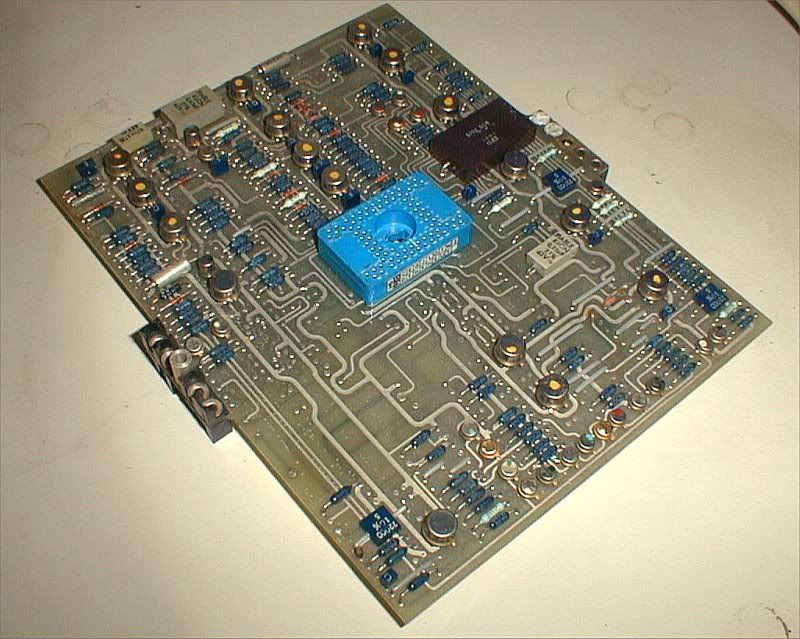
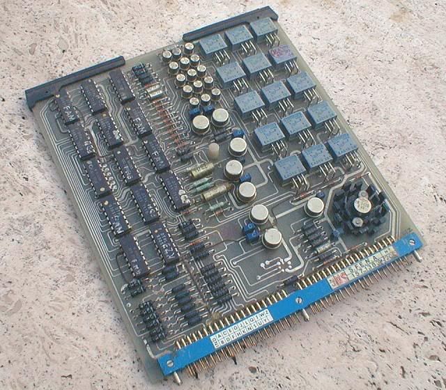
I have the rare privilege of actually having one of those rare "secret" air intake computers (AICU) sitting right next to my desk.
The circuit boards are mostly quite neat, with only the odd wire strap here and there.
However, the wiring of the unit itself, between the connectors, is a nightmare.
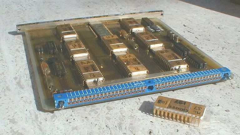
This is one of the PROM boards from the AICU, with one of the PROMs taken out of its socket. I have more photos, but will have to download those first, if anyone is interested.
Landroger
Don't forget that all the computing in the AFCS computers was analog, not digital!
The vast majority were LM101As, with 741s in non-critical locations, and the odd LM108 for the really hiigh-precision stuff.
We did not always do the kind of "butcher job" I described for the A/T. If there was enough time between major mods, the "firm" would redesign the board(s) and send us a new set, and the old ones would be binned... it made for better reliability. I kept a few as souvenirs.
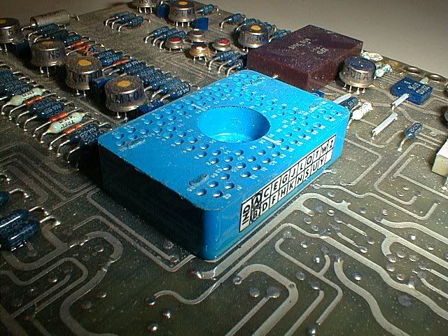
It's the big blue "thing" at the centre of the board, with no less than 80 pins.
This is the back of the card
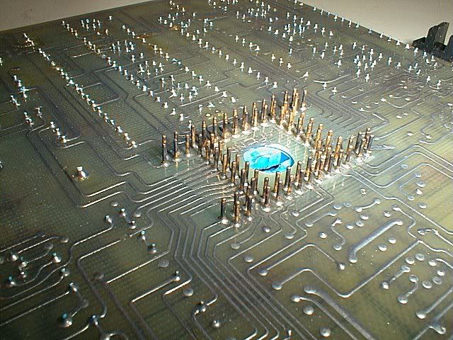
This is the central connector closer up
The idea wasn't bad at first sight.... it allowed stacking three boards on top of each other, so that many signals could pass from one board to another without any intermediate wiring. A small motherboard with a fourth conector would then take certain signals to other stacks, etc.
Another claimed advantage was that it made the board layout easier.
What was learned only gradually was that those connectors were hideously difficult to solder in place, and even more difficult to repair. Concorde was too far "on the way" to redesign the entire AFCS, so we learned to live with them, but the concept was abandoned afterwards.
The central connectors were only used for the analog boards ; the logic boards used more conventional 84-pin connectors on one side.
This is one of the logic boards.
Re the weight question, I would say M2dude 's answer is a lot better than mine, so ignore my remarks.....
Re the wiring, Concorde had about 300km of it.
IIRC the A380 Flying Hippo, which is vastly bigger, "only" has about 500km of wiring, and it seems a lot of that is the IFE (in-flight entertainment)
CJ
Subjects
AFCS (Automtic Flight Control System)
AICU (Air Intake Control Computer)
Intakes
Links are to this post in the relevant subject page so that this post can be seen in context.
Reply to this quoting this original post. You need to be logged in. Not available on closed threads.