August 25, 2010, 17:15:00 GMT
permalink Post: 5891869
You are right on the button first time, the white paint finish is for heat reflection purposes. (When I worked at Filton/Fairford I remember reading a document showing the difference in 'hot soak' supersonic skin temperatures for white and black paint finishes. I'm afraid I can't remember any figures (it was a couple of million years ago ) but there was quite a surprising difference.
G SXTY
A hearty welcome to this thread, and thank you for your very kind comments; I'm sure I speak for all the Concorde people here when I say that it is quite amazing that so many people, both aviation professionals as well as more 'normal' people are so fascinated by what most of us still regard as the finest aircraft ever to grace the skies. Your comment about 'men with slide rules' is so totally correct; I still remember the No7 & No8 design offices at Filton, these were huge rooms filled with draughtsmen's boards, a horde of designers, all without a single computer in sight.
Dave Rowland is a total gentleman as well as being an extremely knowledgeable flyer too, and I know he (like most of us) would be happy to talk about Concorde until the cows come home.
ChristiaanJ
Aghhhh The dreaded AICU. I'd almost forgotten the innards, as you say the motherboard wiring was a total nightmare (good piece of knitting I seem to remember). As far as the 'secret' bit of the AICU, I think we all know that is a little bit of Concorde mythology, more science museum than secret really. Around ten years ago we had some fairly substantial modifications done to the units, due to component obsolescence. (I seem to remember that some of the components concerned were not only out of production, but only a few hundred examples existed worldwide}. I do remember that the power supply board, resolver demodulator boards as well as a couple of others were replaced with new ones using modern components. The modification did do wonders for component reliability.
The PROM board that you have the photo of reminds me of a really amusing anecdote, told to me by Dr Ted Talbot a while ago. Now Ted is one of the true fathers of the Concorde air intake, an absolute genius as well as being a really pleasant gentleman indeed. I'm pleased to say that when I met him a few months ago, he was still as sharp as ever in his advancing years.
The story goes like this: Much of the Concorde intake development trials were flown out of Tangiers and Casablanca, where cold stratospheric temperatures would be guaranteed. Software changes as a result of the flight trials had to be done in there and 'the field'. The way that you made programmed the PROMS was by 'burning' each individual logic gate with a 9v battery. It was highly specialised, as well as extremely tedious work indeed, as we can all well imagine. Anyway, in while he was in Tangiers with aircraft G-AXDN, Ted had arranged for a rather lovely looking lady to be flown out to do his ROM programming. The HS 125 from Filton landed at Tangiers and taxied in and parked next to Concorde, and all the flight test people were waiting on the tarmac. The door of the 125 opened and out stepped this really leggy lady. 'who's the bint then ?' pipes up a really gritty airframe fitter, in a really broad Bristol accent. Without giving it a thought, Ted chirps 'she's come to blow my proms'. The little fitter grunts, glares at Ted and comes out with 'typical office staff, you get all the ***ing perks'.
Subjects
AICU (Air Intake Control Computer)
Filton
G-AXDN
Intakes
Links are to this post in the relevant subject page so that this post can be seen in context.
Reply to this quoting this original post. You need to be logged in. Not available on closed threads.
August 25, 2010, 19:39:00 GMT
permalink Post: 5892167
As M2Dude described the rearwards transfer of fuel during acceleration was meant to be an automated process but in reality there was a lot of manual input. The first requirement of the F/E was to match the rearwards movement of the C of G to that of the ever increasing Mach number. If this was proving to be no problem he would take over the transfer manually by switching off the pumps on one side of tank 9 or 10 so as to pump only to either tank 5 or 7. This was because if you transferred evenly to these tanks due to their different shape size and position the aircraft would go out of trim laterally so the F/E would pump rearward just to one tank so as to keep the C of G going aft whilst maintaining lateral trim.
Being Concorde nothing was straight forward , which meant that when Tanks 5 and 7 ran out and you started using tanks 6 and 8, their size shape and position,was exactly opposite to that of tanks 5 and 7 so it now required the F/E to pump fuel the opposite way across the ship, using various valves and pumps, so as to keep the aircraft in trim laterally.
All the time he had to maintain the trim so as to keep an elevon trim of \xbd deg down, which as fuel was burnt required him to trickle fuel forward from tank 11. On the longer trips such as those to and from BGI the fuel towards the end of cruise became quite low and to stop fuel in the collectors from dropping below 1000kgs each, fuel would be transferred from tank 11 into the collectors until the
C of G had reached it's forward limit at Mach 2.0 of 57.5 %. If then the collectors dropped to 1000kgs the aircraft had to descend to subsonic heights and speed.
Surges
Surges were not an uncommon or common event on Concorde,but when they happened as they usually affected both engines on that side the aircraft would lurch /yaw and everybody on board would know about it as \x93Her In Doors\x94 would testify to that when glasses full and otherwise ended up in her lap during the meal service when a surge occurred.
The drill required all engines to be throttled to a predetermined position and the intake and engine control switches moved to their other position. If this stopped the surge then the throttles were restored to their cruise power a pair at a time and if no surge re-occured then the aircraft would return to cruise / climb
The crews post surge action was normally to have a cup of tea and light up a cigarette.
In the early days on a flight between London and Bahrain when the aircraft was in supersonic cruise the F/E who was a mature and refined gentleman, had to go to the toilet, which was just behind the front galley, and whilst there the engines surged. He was seen running from the toilet to the flight deck with his trousers around his ankles, which was a hell of shock to his refined nature
Enough for now sorry about the length
Subjects
Elevons
Engine surge
Galley
Intakes
Trim
Links are to this post in the relevant subject page so that this post can be seen in context.
Reply to this quoting this original post. You need to be logged in. Not available on closed threads.
August 25, 2010, 21:05:00 GMT
permalink Post: 5892328
The way I understood the story was that they tried to collect as many reasonably reliable spare AICUs for the last few delivery flights, so as not to have to suddenly cancel a flight.
The AICU was right at the top of the list of "unscheduled removals". IIRC the tea maker was second...
"... 'burning' each individual logic gate with a 9v battery." I believe you, thousands wouldn't... Didn't you have at least some sort of programming unit?
I went through a similar exercise around 1976, but at that time at least we had a programming "suitcase", that let you copy the original in RAM, modifiy bit-by-bit with a keyboard, then 'burn' the PROM (or EPROM, by then) 'automatically'. Still took half the night....
Funny in a way how these things have stuck in our memories... But then, yes, Concorde was unique.
I've said this elsewhere, but I don't mind repeating it... in those days, there were two programmes to be part of. One was Apollo, the other was Concorde. And I've had the chance to be part of one of them.
CJ
Subjects
ADC (Air Data Computer)
AICU (Air Intake Control Computer)
British Airways
Intakes
Links are to this post in the relevant subject page so that this post can be seen in context.
Reply to this quoting this original post. You need to be logged in. Not available on closed threads.
August 25, 2010, 22:17:00 GMT
permalink Post: 5892476
The prototypes used a SAGEM/Ferranti system, replaced by a Litton system on the preprods, then Delco on the production aircraft.
There may have been magnetic core in the prototype INS.
As to the AICS (air intakes) and AFCS (automatic flight control), the answer is a definite NO. The AICUs used PROMs (fuse type, not EPROM) and the AFCS was entirely analog.
Some of the systems were even more 'antique'...
The ADC (air data computer) for instance was still largely electro-mechanical.
And those nifty NAV and COMM frequency selectors, that always stand out on cockpit pictures... no electronics at all, just a set of wafer switches, and about thirty wires linking them to the transmitters/receivers.
CJ
Subjects
ADC (Air Data Computer)
AFCS (Automtic Flight Control System)
AICS (Air Intake Control System)
AICU (Air Intake Control Computer)
INS (Inertial Navigation System)
Intakes
Links are to this post in the relevant subject page so that this post can be seen in context.
Reply to this quoting this original post. You need to be logged in. Not available on closed threads.
August 26, 2010, 00:07:00 GMT
permalink Post: 5892703
It's so great to have a Flight Engineer's input into this fascinating thread. Your write up on the complexities of managing the fuel system was something else; the best such description I've ever read. I'm still wetting myself with your story about the E/O coming out of the loo with his trolleys around his ankles after a surge. (Not you I hope
 ).
).
The original air intake that was in use for the first few years of airline operation was as you know far more prone to surging than the later modified intake with the thinned and lowered bottom lip, which was far more stable and forgiving. Not only was the 'new' intake more stable, a new leading edge fitted to the rear ramp as part of the same modification, at a stroke cured the very serious ramp vibration issue, that was causing intake structural problems at lower supersonic Mach numbers. The most impressive change of all was a fuel saving of around 1.5 Tonnes per Atlantic crossing, with even bigger improvements in cooler temperatures. A major software change obviously accompanied this modification.
ChristiaanJ
YEP! I remember now, the ADC/DAC board definitely WAS one of the candidates that were modified.
I think you will find the tale about AICUs being removed after museum delivery flights was more urban myth. The only units that I can remember being removed or relocated were the ground power protection unit, the TCAS processors and the radar transceivers. (BA had retrofitted their aircraft with a superb Bendix system a few years earlier, and the same units (with windshear detection re-enabled) are used on other aircraft types).
As far as ferrite cores are concerned, asked by DozyWannabe , the original Delco C1VAC INS fitted to the BA Concorde aircraft did utilise ferrite cores. These were replaced with CMOS EPROMs when a modification was carried out in the early 90's, in which a navigation database was fitted to the units. The fuel consumed and total fuel remaining indicators definitely used a ferrite core memory. These electronic displays used an internal memory in case of power interrupts. As far as AFCS goes, can you check your records? Although, as you say, a completely analog system (with the exception of the ITEM test computers) I seem to remember that the Safety Flight Control Computer used a ferrite core for the flying control strain gauge null memory. I could be wrong here, but I can't remember any other NVM in use at the time.
Galaxy Flyer
I'll leave it to one of my pilot (or F/E) friends to answer this one it that's OK.
Dude

Last edited by M2dude; 26th August 2010 at 00:20 .
Subjects
ADC (Air Data Computer)
AFCS (Automtic Flight Control System)
AICU (Air Intake Control Computer)
British Airways
Engine surge
INS (Inertial Navigation System)
Intakes
Links are to this post in the relevant subject page so that this post can be seen in context.
Reply to this quoting this original post. You need to be logged in. Not available on closed threads.
August 26, 2010, 16:43:00 GMT
permalink Post: 5894137
So the prototypes were equipped with "autorudder" computers. They used pressure sensors in the engines to detect engine failures, and they would then kick in a "pre-dosed" amount of rudder, that would then be "washed-out" gradually while the pilot dealt with the issue and added rudder trim.
They were manufactured by SFENA, and since I was their flight test support at Fairford, they became automatically my "babies".
The computers (analog, big boxes, the same size as the autopilots or air intake computers) were extremely reliable (we had only two passive faults during the entire flying career of 002).
Unfortunately the same could not be said of the pressure sensors, and since it was always easier to "pull" a computer than a pressure sensor, we found a computer on the bench every few weeks, which then had to be taken through a full test spec and sent back with "no fault found", before anybody was willing to look at the sensors.
Luckily a better solution was found, using a lateral accelerometer, and from the preprod aircraft onwards, each big separate autorudder computer was replaced by a single board tucked away in the autostab computer.
Since the function was always "on", there was no separate autorudder engage switch. Many years later, I discovered that several airline Concorde pilots did not even know the function existed....
CJ
Subjects
Auto-stabilisation
Engine Failure
Engine surge
Fairford
Intakes
Rudder
Trim
Links are to this post in the relevant subject page so that this post can be seen in context.
Reply to this quoting this original post. You need to be logged in. Not available on closed threads.
August 27, 2010, 04:59:00 GMT
permalink Post: 5895262
[QUOTE]Going back to expansion and paint. With the aircraft expanding approx 6 inches and a temp change up to 127`c, I guess a special kind of paint; able to withstand such adverse conditions; must have been used? When deciding on the paint specification was any consideration given to the overall weight of the paint?[/QUOTE
Can't remember much about paint spec's, but a lot of experimentation/trial and error was carried out with different paints until the right one was found. I remember when G-BOAD was delivered, that copiuous sheets of paint had peeled off in flight. Finally a superb polyurithane paint was found that did the trick perfectly.
And the 'hat in the gap' stories are quite true.
ChristiaanJ
This was the real beauty of the autostab' on all 3 axis; you could just safely take it all for granted. The Mach 2 engine out case was a classic, as not only would the aircraft yaw towards the dead engine but there was an adverse roll input, where the wing on the same side would LIFT due to the excess intake air for the failed automatically being 'dumped' through the now open spill door. If for any reason the aircraft HAD been under manual rather than autopilot control, then life without autostab would be rather uncomfortable to say the least. And putting further Concorde's achievements in terms of stability; the world's only previous large delta winged Mach 2 aircraft, the B58 Hustler, had the slightly awkward feature in the case of an outer engine failure at Mach 2, in that the yaw forces were sufficient to tear the fin off. This happened on more than one occasion during service life of the Hustler, but engine failure (or far more likely a deliberate precautionary shut-down) although hardly a non-event in the case of Concorde, it was routinely dealt with without drama or danger.
Dude
Subjects
Auto-pilot
Auto-stabilisation
Engine Failure
Engine Shutdown
Expansion
G-BOAD
Intakes
Links are to this post in the relevant subject page so that this post can be seen in context.
Reply to this quoting this original post. You need to be logged in. Not available on closed threads.
August 27, 2010, 19:42:00 GMT
permalink Post: 5896703
Remember that Concorde had no APU and no across the ship ducting for stating engines, therefore prior to push an air start unit was plugged into each pair of engines and the inboard engines would be started. This allowed, after push back, air from each inboard engine to be used to start it's outboard engine.
The other good reason for starting the inboards prior to push was that with no APU the cabin temp would rise quite quickly [specially in places like Bahrain in summer] and never mind the passengers
comfort, but some of M2dude and ChristiaanJ fancy electronic equipment was very temp sensitive , especially those intake control units down the rear galley. With Two engines running we could use their bleed air to at least try and hold the cabin air temp during the push back
When we first started LHR-IAD flights[ prior to thin lip///54% and other mods which improved our range] some thought was given to towing the aircraft to the taxi way near the end of the runway before starting engines so as to save fuel. I do not remember this actually ever being done though.
\
Subjects
APU (Auxiliary Power Unit)
Bleed Air
Galley
Intakes
Links are to this post in the relevant subject page so that this post can be seen in context.
Reply to this quoting this original post. You need to be logged in. Not available on closed threads.
August 31, 2010, 18:04:00 GMT
permalink Post: 5904352
).
In reality the Soviets really lacked both propulsion technology as well as the systems expertise required to build an aircraft with even a remote hope of Mach 2 cruise, let alone safe and comfortable enough for fare paying passengers. The original aircraft had all for engines in one giant nacelle, and the landing gear retracted into the engine inlet duct itself, great for an undistorted flow path to the engines
 . The variable inlets were manually operated by the flight engineer as well, no automatics here. In the mid 1970's the Russians even approached PLESSEY to build a digital engine control unit for the TU144. A similar PLESSEY unit had been VERY successfully flight trialled on production series aircraft 202 (G-BBDG) and only lack of funds prevented it being used on the production aircraft. As this unit could obviously be used for Soviet military applications, there was objection from the UK government, and more than just a little trans-Atlantic pressure applied, and so this venture never happened.
ANYWAY, back on topic

Lurking SLF
No problem at all Darragh, please keep visiting us and post here also anytime.

Nick Thomas
Now for the PFM bit, equally eloquently alluded to by Bellerophon:
DEBOW itself was maintained by a special sub-idle datum in the electronic Engine Control Unit, and once the engine was accelerated towards normal idle (61-65% N2, depending on the temperature of the day) even if the switch described by Bellerophon was accidently re-selected, an electronic inhibit gate in the ECU prevented this sub-idle datum from being used again that engine cycle.
 ). Rotation of either wheel (more a giant knob actually) merely shifted the neutral datum of the relevant artificial feel unit, which in turn shifted the rudder pedals or control yoke; the resolvers for the FBW system would in consequence demand this 'trimmed' control surface movement.
Dude
Subjects
FBW (Fly By Wire)
G-BBDG
Intakes
Landing Gear
Rudder
Trim
Tu-144
Links are to this post in the relevant subject page so that this post can be seen in context.
Reply to this quoting this original post. You need to be logged in. Not available on closed threads.
September 02, 2010, 23:55:00 GMT
permalink Post: 5909785
As far as your adventure goes, in the early days of Concorde operation there was an on-going issue of hydraulic seal failures. This led to the sort of thing that you described, where a major seal failure would occur, resulting in the loss of a main system. The standby Yellow system would be switched in to replace the failed one, and depending on the nature of the initial failure, could leak out of the same failed seal. (There were a couple of 'common areas', they were the intake spill door jack, and the Powered Flying Control Units; failures here could result in a double system fail). Your incident was almost certainly due to one of these cases. In the early 1990's the original Neoprene hydraulic seals were replaced with a new Viton GLT seal; this material had far superior age shrinking characteristics to Neoprene, and more or less cured the problem overnight. Eventually all the seals in each aircraft were replaced, and apart from a very few isolated cases, dual system losses were eliminated forever. Air France suffered a similar proportion of failures, however as their flying hours were a fraction of BA's, the effects were not as immediately apparent.
As far as far as the hydraulic contamination story goes, this happened in 1980 but involved one aircraft only, G-BOAG, but in it's original registration of G-BFKW. (having previously been on loan from British Aerospace, where it flew originally as a 'white tail' under this registration). The fragile nature of Concorde hydraulic fluid was not fully understood at this time, and as you say, a hydraulic drum dispenser had inadvertently been left exposed to the atmosphere, and had subsequently suffered water contamination, and this contaminated fluid had found it's way into G-BOAG. Now this hydraulic fluid, CHEVRON M2V has only two vices: One is that is extremely expensive, and the second is that it is highly susceptible to water contamination, EXTEMELY SO. If my memory serves me correctly, the maximum allowable level of water in the fluid is about 8ppm. (parts per million) and the fluid that was analysed after G-BOAG's problems was at about 30 ppm. The water deposits in the fluid gave the equivalent effect of 'rusting up' of critical hydraulic components. I was investigating an air intake control defect the previous day to the incident, but like everybody else had no idea that the real issue here was one of major systems contamination. We were all convinced that we had nailed the problem, only to find that the aircraft turned back on it's subsequent LHR-JFK sector with more serious problems, not only affecting the air intakes, but the artificial feel system also. It was now that we realised that there had to be a hydraulics problem here, and after fluid analysis, the awful truth was discovered. After this event, and the fragilities of M2V fluid were better understood, a strict regime of housekeeping was put in place in terms of fluid storage, and no such incidents with BA ever occurring again. The aircraft itself did not fly again for nine months, all components that were affected were removed from the aircraft and completely stripped and overhauled. Also all of the system hydraulic lines had to be completely purged, until there were no further traces of any contamination. After the aircraft was finally rectified, she successfully again returned to service with her new 'BA' registration of G-BOAG. However the following year, during a C Check, it was decided that due to spares shortages, and the closure of the LHR-BAH-SIN route, there just was not being enough work for seven aircraft, and therefore G-BOAG would be withdrawn from service. (In terms of spares, BA at the time for instance only had six sets of aircraft galleys, as aircraft went in for C checks the galley was 'robbed' to service the aircraft coming out of it's own C check). The aircraft was parked in a remote hangar, and was only visited when a component had to be 'robbed' for another Concorde, and the aircraft soon fell into disrepair, was filthy externally and became a really sad sight. Many people (not myself I might add) were adamant that G-BOAG would never fly again. However, in 1984 things had really started to improve for Concorde, with the charter business increasing and the LHR-JFK route in particular becoming a staggering success. It was decided that OAG would be returned to an airworthy condition. In 1985, with a fresh new interior, and with the new BA colour scheme, she was finally returned to service; and remained as one of the mainstays of the fleet right up to the end of Concorde services in October 2003. She now resides at the Boeing Museum of Flight in Seattle. (I have particularly fond memories of G-BOAG; in a previous post I mentioned flying through an electrical storm in late 1991 over Saudi Arabia, while returning from BKK-BAH to LHR. What I forgot to mention was the spectacle of DOZENS of fierce fires burning on the ground, towards our starboard horizon. These were Sadams oil fires, still burning in Kuwait. It made a sombre contrast to the amazing electrical spectacle right in front of us).
As far as low speed flying control activity was concerned, this was a combination of the fairly flexible outer wing sections, being buffeted by low speed turbulence (the wing tip tanks 5A & 7A also being empty), as well as some autostab inputs. This was perfectly normal, and part of the design our aircraft. However the development aircraft had even more flexible outer wing sections, which used to almost straighten up in high speed flight. However due to fatigue concerns, external lateral stiffeners were added to the underside of the wings during production of the airline aircraft. (these can be easily seen from underneath the wings, just outboard of the nacelles). Unfortunately these external stiffeners also resulted in over a one tonne fuel penalty to the production aircraft, due to increased weight, as well as higher drag in a critical part of the wing aerodynamic surface.
Dude
Last edited by M2dude; 3rd September 2010 at 00:07 .
Subjects
Auto-stabilisation
Boeing
British Airways
Fatigue
G-BFKW
G-BOAG
Galley
Hydraulic
Hydraulic Failure/Contamination
Hydraulic System - YELLOW
Intakes
LHR
LHR-JFK Route
Links are to this post in the relevant subject page so that this post can be seen in context.
Reply to this quoting this original post. You need to be logged in. Not available on closed threads.
September 03, 2010, 08:43:00 GMT
permalink Post: 5910383
This of course is one for one of my pilot friends to answer properly again, but as galaxy flyer says, it's an 'eye to wheel' issue here when compared to other aircraft.
galaxy flyer
Again best answered by learned gentlemen such as my friends EXWOK or Bellerophon, but to the best of my feeble knowledge a resounding NO, at least as far as CRUISE flying was concerned. As the majority of the flight was carried out between FL500 and FL600 there was really no weather as such to avoid during supercruise. (As has been previously posted, at Mach 2 you would invariably be above FL500). Only at extremely low latitudes where the tropopause could theoretically extend up to around 70,000' was there ever any chance of seeing any cloud anywhere near your cruise altitudes. The only turbulence as such you would ever encounter was as the result of a temperature shear, but these never felt to be too much in the way of 'bumps' to me. And again, only at very low latitudes did you encounter severe shears anyway; anything encountered on the North Atlantic was generally very mild and civilised.
A CONCORDE PARADOX
The tropopause issue here is an interesting one, in that the coldest stratospheric temperatures we ever encountered were close to the equator, whereas the WARMEST temperatures possible are over the POLES
 ) to be a success, and could compete side by side with Concorde.
ANOTHER CONCORDE PARADOX
If anyone wonders why when you flew faster you burned less fuel, it was primarily down to drag, actually a thing frighteningly termed as 'pre-entry spill drag'. As most people (???) are aware, the Concorde engine inlet utilised a series of carefully controlled and focused shockwaves to slow the air down entering the engine; in 14 feet of engine intake you lost in the order of 1,000 mph of airspeed! Now most of these different shocks varied with a combination of intake variable surface angle, intake local Mach number and also engine mass flow demand. However the oblique shock coming off the top lip of the intake produced a shock that varied with Mach alone, and would project downwards, just forward of the intake bottom lip. Due to the air downstream of this fairly weak shock still being supersonic, a measured amount of this air spills downwards, away from the intake. If you can possibly picture it, we have this wall of air spilling downwards over the lower lip of all four intakes, the combined effect of this supersonic forespill is a fair amount of drag. The faster we go, the more accute the angle of the shock and therefore the less air is spilled, and in consequence the lower the spill drag. Remembering that cool temperatures could produce a higher Mach number, temperature really could either be our friend or enemy, but cool was COOL

I hope this explanation does not sound like too much gibberish, but it really was a fact that 'More Mach = Less Fuel'. Hope it makes some sense.
Dude
Last edited by M2dude; 3rd September 2010 at 11:08 . Reason: clearing up some gibberish
Subjects
FL600
Fuel Burn
Intakes
Shockwave
Super-cruise
TMO (Temprature Max Operating)
Temperature Shear
Tu-144
Links are to this post in the relevant subject page so that this post can be seen in context.
Reply to this quoting this original post. You need to be logged in. Not available on closed threads.
September 03, 2010, 14:57:00 GMT
permalink Post: 5911218
 Thanks for the explanation though.

Were the Braniff crews trained specificially for Concorde or were they supplied as part of the lease package and what were they thinking flying a supersonic machine along the USA subsonic route? Marketing exercise???
Subjects
Braniff
Intakes
Links are to this post in the relevant subject page so that this post can be seen in context.
Reply to this quoting this original post. You need to be logged in. Not available on closed threads.
September 05, 2010, 12:12:00 GMT
permalink Post: 5915084
On the technical side of things there were meetings between the two airlines, both together and jointly with the airframe and engine manufacturers, but on a day to day basis there was precious little exchange of information, and you'd have thought that we (BA) were the only operator of Concorde, as I'm sure the AF guys felt the same also. In all of my 30+ years on Concorde, I personally went to CDG only once for an exchange of technical views and to help them out with an air intake defect.
I'm so glad that you are enjoying this post, it's great to have you here telster. (It's certainly forcing me to look deep into the dark corners my poor old grey matter).
Dude
Subjects
Air France
British Airways
CDG
Intakes
Links are to this post in the relevant subject page so that this post can be seen in context.
Reply to this quoting this original post. You need to be logged in. Not available on closed threads.
September 08, 2010, 11:04:00 GMT
permalink Post: 5921405
The emergency generator (and generator control unit) were license built replicas of the units fitted to the F4K and F4M.
The air intake void (Pv) pressure sensor, built by Garrett Aireseach, was used in another 'case' as an inlet pressure sensor on the F14.
Carbon wheel brakes, pioneered on Concorde are now used by just about every modern commercial AND military aircraft. (Although originally trialled on a VC10 in a single brake installation).
(Already bleated on about Airbus pinching our audio warning tones etc).
The Triplex 10-20 glass, developed for and used on the visor panels were used in the automotive industry for many years to come.
I'm sure that there is stacks more.....
Dude
Subjects
Airbus
Braking
Intakes
Visor
Links are to this post in the relevant subject page so that this post can be seen in context.
Reply to this quoting this original post. You need to be logged in. Not available on closed threads.
October 02, 2010, 08:45:00 GMT
permalink Post: 5969581
The Inner Elevon Light, plus 'PFC' red Master Warning is triggered by:
a) The Green Flying ControlComparator
b) The Blue Flying Control Comparator
c) Either Comparator
The correct answer is (b).
Another flying controls question I can remember is:
Outer Elevon Neutralisation is triggered at:
a)Vmo + 10 KTS
b)Vmo + 15 KTS
c)Vmo + 25 KTS
The correct answer here is (c).
The pass mark in these exams was 75%, with penalty marking applied for any wrong answers. I always found the worst part was the fact that the exams were on a Friday afternoon after lunch
Nick Thomas
From what you said about the 'lady' being ahead of her time, I would certainly agree with you here; in my view she was generations ahead of everything else.
nomorecatering
As far as ground school notes, mine are all out on long term loan (MUST get them back). The ground school are totally priceless and I am sure that there are many complete sets lying around in atticks/bedrooms/garages/loos etc.
Dude
Last edited by M2dude; 2nd October 2010 at 13:40 .
Subjects
British Airways
Brooklands
C of G
Elevons
Filton
Fuel Pumps
Hydraulic
Intakes
JFK
LHR
LHR-JFK Route
Simulator
Trim
Links are to this post in the relevant subject page so that this post can be seen in context.
Reply to this quoting this original post. You need to be logged in. Not available on closed threads.
October 08, 2010, 09:06:00 GMT
permalink Post: 5981420
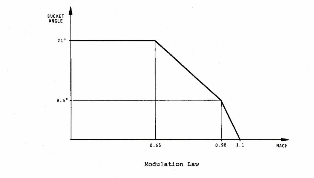
Now if we are locked at the 10 degree position we are at a position that will give us significant but tolerable losses throughout the flight envelope.
Subjects
Expansion
Flight Envelope
Intakes
Nozzles
Thrust Reversers
Links are to this post in the relevant subject page so that this post can be seen in context.
Reply to this quoting this original post. You need to be logged in. Not available on closed threads.
October 08, 2010, 13:48:00 GMT
permalink Post: 5981946
I remember reading Stanley Hookers book "Not Much of an Engineer" (I know the feeling
 ), in which he explains how at Mach 2 the Olympus is only providing about 8% of the total thrust but then goes on to say that at the low speed end of the take-off run it was 100% of the thrust so his designers were not let off the hook. That falls to 82% in subsonic cruise.
Ah, found the figures for Mach 2, the inlet provides 63% of the total thrust, exhaust nozzles 29%. That certainly explains why the thinning and re-profiling of the inlet lip was so important to improving the fuel burn, and hence range.
Subjects
Fuel Burn
Intakes
Nozzles
Sir Stanley Hooker
Links are to this post in the relevant subject page so that this post can be seen in context.
Reply to this quoting this original post. You need to be logged in. Not available on closed threads.
October 09, 2010, 19:10:00 GMT
permalink Post: 5984488
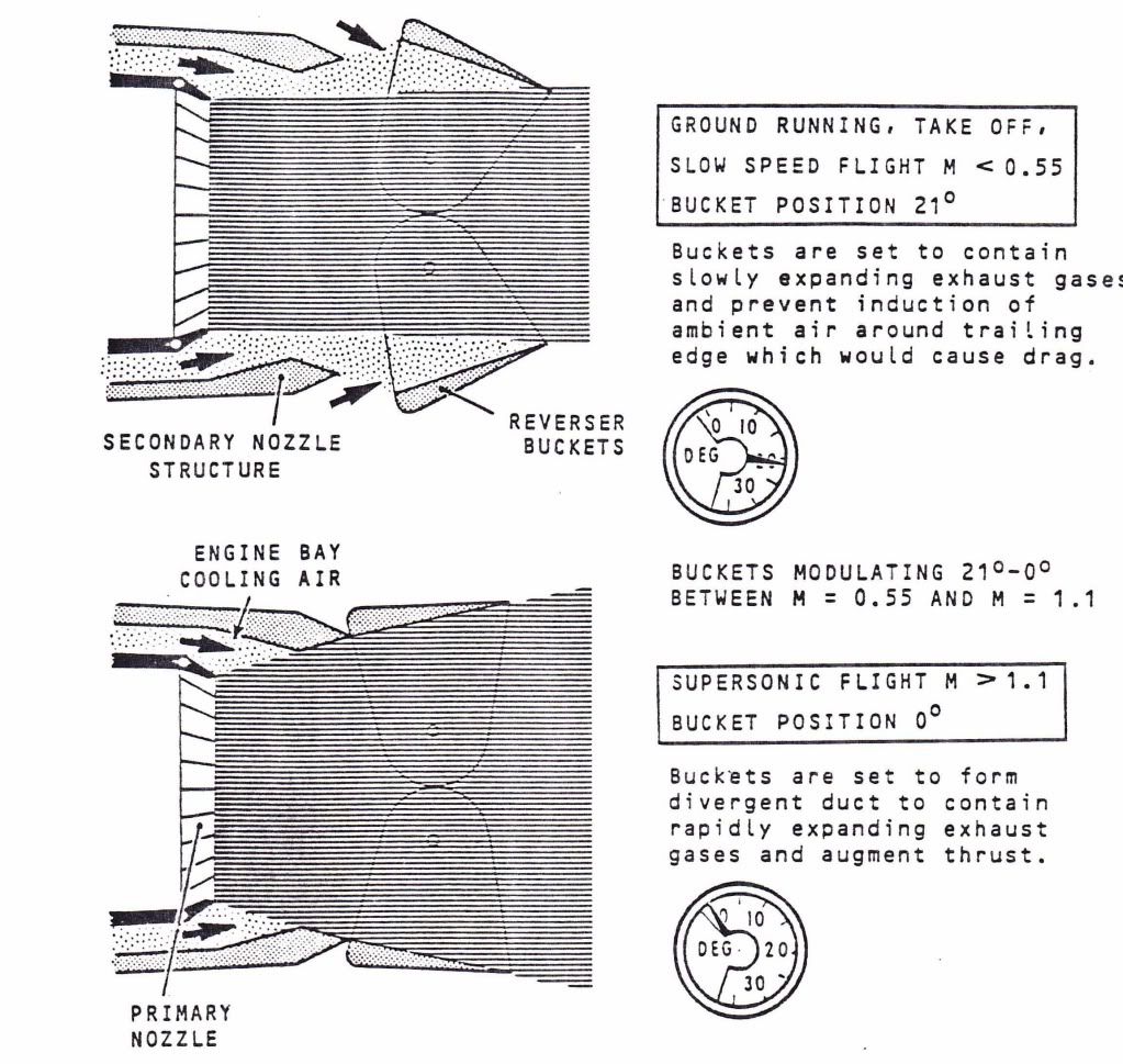
The story I heard when I was an apprentice at Hurn was that, compared to the prototype multi finger nozzle and separate reverser, the production nozzle was:-
1. More efficient.
2. Lighter.
3. Simpler.
4. Cheaper to make and maintain.
The original secondary nozzle was 'freely floating, with no actuation; the thrust revereser itself was a pair of cascade doors, driven by an air motor. Tertary air doors opened at low speeds to admit ambient air into the nozzle anulus, instead of the eyelids of the later 'buckets'.
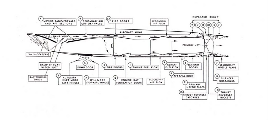
If you look at the diagram below you can see what a complicated animal the prototype powerplant was. The intake dump door (alternative name for spill door) was hinged both at the front AND the rear; either hinge mechanisms automatically releasing at specific Mach numbers. It was the mechanical nightmare that the diagram suggesrs.
Dude
Last edited by M2dude; 9th October 2010 at 21:54 .
Subjects
Intakes
Nozzles
Rolls Royce
Thrust Reversers
Links are to this post in the relevant subject page so that this post can be seen in context.
Reply to this quoting this original post. You need to be logged in. Not available on closed threads.
October 09, 2010, 19:26:00 GMT
permalink Post: 5984535
).
As far as ChristiaanJ's point about the Olympus; the only plans I ever saw were for the Olympus 593 Mk 622, which gave a thrust increase of around 4,000 lbs static thrust but retained reheat. I know there were definate plans for a larger diameter engine (not just the LPC) that would have naturally required a larger intake. As far as the intake irself went, believe it or not, the plan was to remove the rear ramp altogether.
The 'B' would have been a hell of an aeroplane; but the 'A' was still absolutely amazing in any case.
Dude
Subjects
Afterburner/Re-heat
Elevons
Intakes
Olympus 593
Links are to this post in the relevant subject page so that this post can be seen in context.
Reply to this quoting this original post. You need to be logged in. Not available on closed threads.
October 10, 2010, 15:13:00 GMT
permalink Post: 5985923
 but still riveting stuff nonetheless.
May I ask a question about another aspect of Concorde life? In my own job as a CT/MRI scanner engineer, I was for many years a 'Registered Radiation Worker' and indeed I still wear the equivalent of a film badge. My annual dose though was and is tiny, virtually background. However, I remember seeing a chart from the Radiological Protection Board some years ago, that seemed to suggest Concorde Crews had the highest radiation dose in any industry routine operations.

Was this true and did Concorde crews wear a film badge as I did? I understand that 'ordinary' flight crews get quite a radiation dose, but nothing like the 60,000ft doses the lady permitted?
Roger.
Subjects
Intakes
Nozzles
Radiation Exposure
Links are to this post in the relevant subject page so that this post can be seen in context.
Reply to this quoting this original post. You need to be logged in. Not available on closed threads.